

- What a pressure switch in a compressor is for
- How a pressure switch works
- How to use a pressure switch to control a compressor
- Adjusting pressure switches
What a pressure switch in a compressor is for
The air compressed by the compressor piston is forced into the pressure vessel, i.e. the air tank. The pressure switch makes sure that the compressed air in the air tank is at the pressure we need. It works simply: the pressure switch monitors the pressure in the air tank, and as soon as the pressure drops below the set lower limit, the switch closes and completes the electrical circuit. Thanks to that, the electric motor driving the compressor starts up. As soon as the pressure rises to the set upper limit, the pressure switch opens and the compressor stops. Because of consumption, or also because of a change in temperature, the pressure in the air tank drops again. When the pressure falls below the set lower limit, the switch turns the compressor on again. And so it goes round and round.
@KATEGORIE@(/tlakove-spinace/)(10,random)(slider)
So the pressure switch starts and stops the compressor so that the pressure in the air tank always stays between two set pressure values:
- cut-in pressure – the lower pressure limit at which the compressor switches on
- cut-out pressure – the upper pressure limit at which the compressor switches off
The difference between the cut-in and the cut-out pressure is called hysteresis or also the switching differential. You will find the value among the parameters of pressure switches.
How a pressure switch works
A pressure switch, also called a pressostat, is a device that switches an electrical circuit depending on the level of pressure. The switch has two basic parts:
- A sensor for measuring pressure – a flexible element, e.g. a diaphragm fitted with strain gauges. The air pressure deflects the diaphragm, which changes the electrical resistance in the strain gauges. And because the strain gauges are connected in a measuring bridge, the magnitude of the acting pressure can be determined from the electrical signal.
- Electrical contacts, which close or open the electrical circuit according to the measured pressure.
Normally open, normally closed and changeover contacts
According to their function we distinguish switches with normally open, normally closed and changeover contacts. When choosing a switch, we can go by the symbol that indicates the function of the switch:
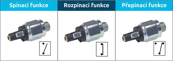
A normally open contact is open in the rest state, i.e. at low pressure (the electrical circuit is broken and the compressor is not running). The normally open contact closes (and starts the compressor) only when the pressure reaches the set value. The abbreviation NO – normally open – is also used for it.
A normally closed contact is closed in the rest state, i.e. at low pressure (the electrical circuit is completed and the compressor is running). The normally closed contact opens (and stops the compressor) as soon as the pressure reaches the set value. The abbreviation NC – normally closed – is also used for it.
Changeover contacts work in such a way that the switch changes over from one contact to the other. The advantage is that this switch is universal. If you are not sure which type of switch you need, get a switch with changeover contacts and use one contact or the other.
A switch with changeover contacts can also be used for fault detection. In one position, trouble-free operation is signalled and this contact can light a green indicator lamp. In the event of a fault, the switch changes over to the other contact, which lights a red indicator lamp.
@KATEGORIE@(/tlakove-spinace--elektromechanicke-42v-5a/)(10,random)(slider)
How to use a pressure switch to control a compressor
To control compressors you can use either simple, inexpensive pressure switches or robust, expensive switches designed for this purpose.
a) Using simple switches
e.g. electromechanical pressure switches of the DRS series for 42 V/5A
I. One pressure switch with a normally closed contact

The simplest solution uses a pressure switch with a normally closed contact whose contacts are rated for low current only. At low pressure the contact is closed, so electric current reaches the motor, which turns the compressor, and the compressor compresses the air. The pressure in the air tank rises until it reaches the set upper limit, i.e. the cut-out pressure. The switch opens and the compressor stops. The air pressure then gradually drops as air is consumed. And when it falls to the lower limit, i.e. the cut-in pressure, the contact closes again, the compressor starts up, the air tank is refilled and the switch opens.
As is usually the case, this simple solution also has its limits:
- It is suitable only for low-output compressors, because the contacts of simple switches cannot take a high current load.
- The switching differential (the difference between the cut-in and the cut-out pressure) may be too small. Then we may find that the compressor keeps switching on and off, even without our having consumed any air. The air that goes into the air tank has been heated in the compressor, and as it cools down the pressure may drop far enough for a switch with a small switching differential to turn the compressor on again. On simple pressure switches the switching differential cannot be adjusted; it is usually 15 to 20 %.
II. Pressure switch with a power relay
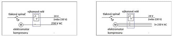
We can deal with the limited compressor output by connecting the pressure switch to a power relay, i.e. a contactor. The relay contacts are designed to take a higher load. That way we can switch even higher-output compressors on and off. The diagram on the left shows the wiring of a single-phase electric motor and the diagram on the right the wiring of a three-phase electric motor.
By adding a power relay we do gain a higher current-carrying capacity, but we are still unable to set the switching differential.
III. A pair of pressure switches with a relay in a latching circuit
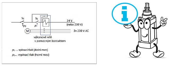
By connecting two pressure switches according to this diagram we solve both limitations – the current-carrying capacity of the contacts for switching powerful compressors as well as the setting of the switching differential.
How does it work?
Pressure sensor S1 has its cut-in pressure set at the lower limit of the operating pressure p1 and switches on the compressor motor.
Pressure switch S2 has its cut-out pressure set at the upper limit of the operating pressure p2 and stops the compressor motor.
The switching differential is set as the difference between the cut-in pressure p1 and the cut-out pressure p2.
When the pressure in the air tank drops below the lower limit p1, switch S1 closes and the motor starts the compressor. The pressure in the air tank rises, and as soon as it reaches the lower limit p1, switch S1 does open, but the compressor keeps running thanks to the bridge formed by the relay with an auxiliary holding contact. However, as soon as the pressure rises to the upper limit p2, the second pressure switch S2 breaks the whole circuit and the compressor stops.
The relay can have either one power contact for a single-phase motor or three power contacts for a three-phase motor, as our diagram shows.
b) A robust pressure switch for controlling compressors
More robust and more expensive pressure switches are suitable for controlling powerful compressors. These switches offer the following advantages:
|
 |
- They have built-in thermal motor protection.
- If an overload or the loss of one or more phases occurred, the three-phase motor would not be able to start and there would be a risk of it burning out. That is why the thermal protection blocks the motor from starting in such a case.
Adjusting pressure switches
With a newly purchased pressure switch you always have to check at what pressure it switches on and off. If the setting does not suit, we change it. For that, switches have a control element, most often an adjusting screw. Pressure switches with an adjustable switching differential have a second adjusting element.
The adjusting elements are fitted either with a calibrated ring or with a slider that shows the pressure values the pressure switch will then be set to. Most often, however, the switch only has a screw without an indicator, so at first we do not know what pressure the switch is currently set to. To set the switch, a pressure gauge also has to be connected to the air tank so that we can watch the pressure changes on it.
Adjusting the cut-out pressure of the compressor
The adjusting screw is usually designed so that turning it to the right increases the cut-in and cut-out pressure and turning it to the left decreases them.
- We fill the air tank with the compressor and first find out from the pressure gauge at what pressure the switch opens, i.e. stops the compressor. Now we know the upper limit, i.e. what cut-out pressure the switch is set to.
- We drain the air tank and find out at what pressure the compressor switches on again. And this is the lower limit, i.e. the cut-in pressure the pressure switch is set to.
- If the given setting does not suit, we change the position of the adjusting element slightly, drain the air tank and repeat the test.
- We repeat the procedure until we reach the required cut-out and cut-in pressure of the pressure switch.
Adjusting the switching differential
With pressure switches that have a fixed switching differential we have to make do with the figure in per cent (usually 15 to 20 %). So if we set the upper limit, i.e. the value of the cut-out pressure, the value of the lower limit, i.e. the cut-in pressure, will be 15 to 20 % lower.
On robust and more expensive switches we will find one more adjusting screw with which we set the switching differential.
- Following the procedure described above, we first set the cut-out pressure and, by draining the air tank, find out the cut-in pressure.
- If the difference between the cut-in and the cut-out pressure does not suit us, we turn the screw for adjusting the switching differential slightly and find out how it has changed.
- We repeat the procedure until we reach a switching differential that suits us.
Please note: Adjusting the switching differential usually shifts both limits, however, both the cut-in and the cut-out pressure. That is why they need to be checked and adjusted
Using a pressure regulator
If we have a pressure regulator available, we do not have to fill and drain the whole air tank. We connect the regulator to the pressure switch and use it to set the cut-in and cut-out pressure. Then we connect the pressure switch to the air tank and check whether it switches on and off correctly. Special workstations for adjusting pressure switches are usually equipped with a pressure regulator