
Choosing a valve to control a pneumatic actuator might seem simple. Perhaps it was in the past, because a few years ago it was true that a valve with the same connection threads was suitable for the actuator. Today, however, in the age of extensive automation, much greater caution is needed when choosing, as valve parameters have multiplied.
Main types of valves:
- electromagnetic valves
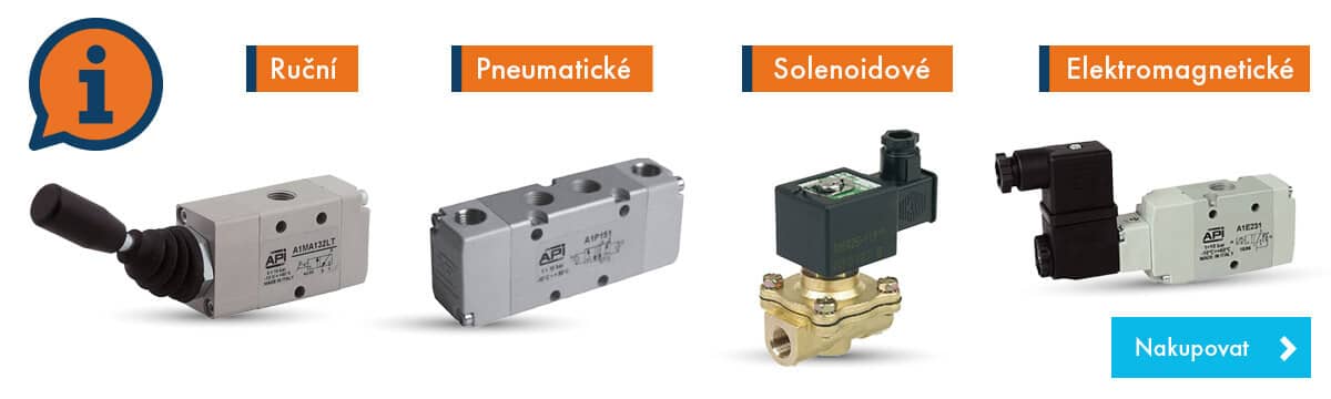
- solenoid valves
- pneumatically operated valves
- manually operated valves
- foot valves
@KATEGORIE@(/solenoidove-ventily/)(10,random)(slider)
Valves are used not only to control pneumatic actuators. Their application can also be found in hydraulic distribution systems, most commonly in configurations with a seat valve or a spool. If the electromagnetic coil is energized, it becomes an electromagnet and generates a magnetic force. This force allows the core to move inside the valve. This way, the valve opens and closes. Valves have various functions like 5/3, 3/2, 5/2, or they can be electrically operated. The most common electromagnetic valves are two-way, two-position seat valves that simply open and close to allow flow when their coil is energized.
Today's complex valves are not just about the open and close function. Imagine, for example, that a miniature cylinder on a large valve extends a long time before the actual opening. And this is one of a hundred examples of what can happen inside the construction. As you can guess, the valve opening time stated in the catalog is often not decisive, because it can be longer than the whole process. Thank goodness we have detailed diagrams available to help us navigate.
Schematic symbols of valves
- each valve position is symbolized by its square, in which the connection of inputs, outputs, and exhausts in a given position is drawn (i.e.: if the symbol contains 2 squares, it is a 2-position valve, if it contains 3 squares, it is a 3-position valve, etc.)
- numbering or letter designation of connections is always by the square symbolizing the basic position
- arrows connecting the ports indicate the direction of air flow; in case the arrows are on both sides, the valve can also be used for flow in both directions
- the air supply and exhausts are usually placed on the bottom side of the square, the outputs from the valves are placed on the top side of the square
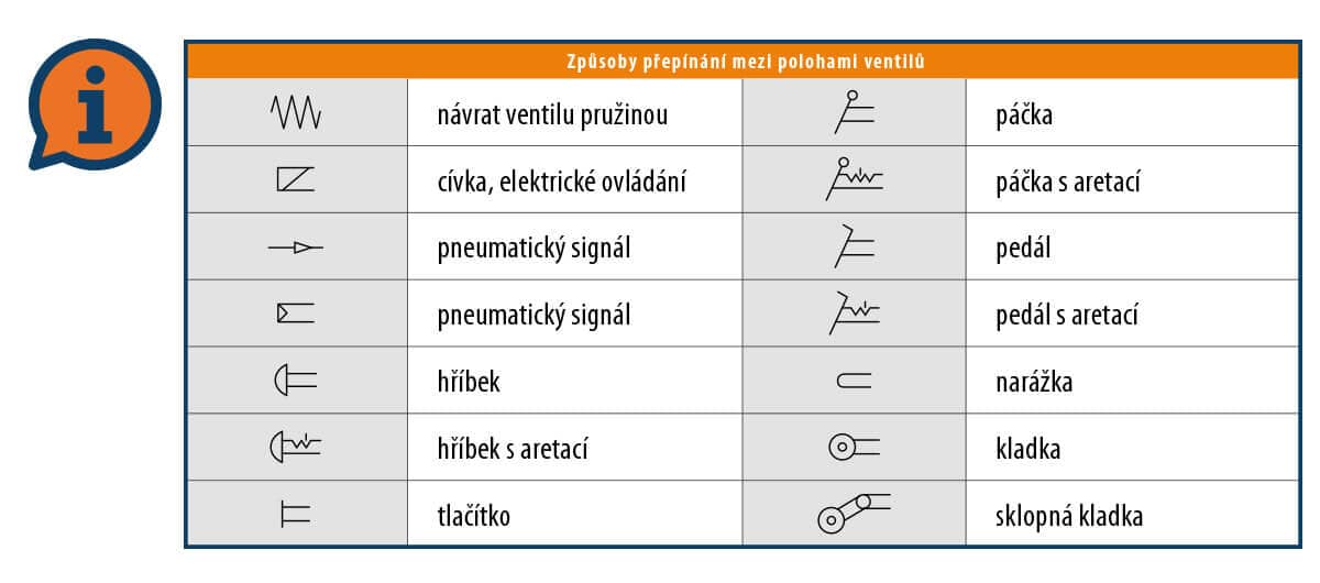
- symbols indicating the method of switching between individual positions are placed on the side of the square; the square they are drawn next to becomes active upon the arrival of a signal (as if it moved to the place of the basic position square)
Brand examples
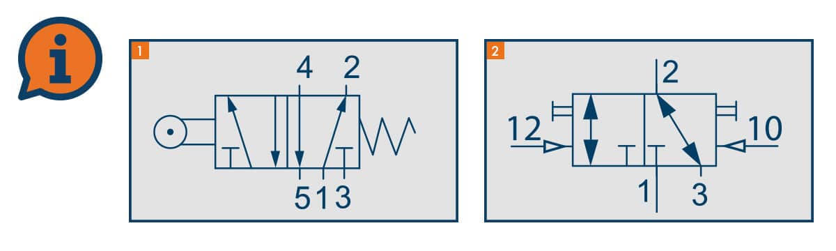
In this symbol we can see 2 squares, so it is a two-position valve. The symbol shows outlets 2 and 4 (at the top), exhausts 3 and 5 and supply 1 (at the bottom). Together that makes 5 ways, so it is a 5/2 valve. The numerical designation of the ports is at the right-hand square, which is therefore where the valve's default position is. In this position air flows from supply 1 to outlet 2, while outlet 4 is connected to exhaust 5. Exhaust 3 is closed. On the left-hand side of the symbol there is roller actuation, so this is a mechanically operated valve. Once the roller is pressed, the valve switches according to the left-hand square (adjacent to the roller symbol). In the second position supply 1 is connected to outlet 4 and, conversely, outlet 2 is connected to exhaust 3, while exhaust 5 is now closed. Pressing the roller has therefore swapped outlets 2 and 4. On the right-hand side of the symbol there is a spring, which means the valve returns to its default position on its own, by means of a mechanical spring.
@KATEGORIE@(/ventily-a-prislusenstvi--elektricke-a-pneumaticke/)(15,random)(slider)
The second example is again a two-position valve. At the default position we see the numerical designation 1 - supply, 2 - outlet and 3 - exhaust. So this is a three-way valve (signals 12 and 10 do not count as ways). In the default position the supply is closed and the outlet is connected to the exhaust. Signal 12 (the arrow indicates an air signal) from the left switches the valve into the position of the left-hand square, i.e. the inlet is connected to outlet 2 (which is why the signal is designated 12 = 10 + 2). Once signal 12 stops, the valve stays out of the default position (bistable function) and remains there until signal 10 arrives from the right, activating the default position (10 = 10 + 0, i.e. it closes the valve). At the sides you can also see tiny button symbols. These represent what is known as manual override, and the valve can be switched in an emergency with a screwdriver, for example.
Differences between valves
A significant number of diagrams tells us that there is also a significant number of valve types. They can be standalone or part of a valve terminal. Adaptation also concerns the switching speed (exceptionally fast processes are provided by special so-called fast valves, which switch up to ten times faster than standard valves because the opening time can be even 1 ms), and the nominal diameter, connection thread, flow rate, or control are also different. There is nothing left to do but to think everything through and calculate.
Most important parameters:
- function
- thread connection
- working pressure
- working temperature
- nominal bore
- flow rate
- coil power consumption
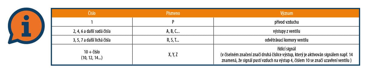
The valve function is always described in the specification, and the diagram can also be helpful. We have already introduced the functions above, but what about all those numbers on the diagrams? What do these markings mean? They describe whether it is a supply, output, exhaust, or control connection. In practice, both markings (numbers or letters) are possible, but marking with numbers is more modern.
Working pressure is also an essential parameter. Thus, determining whether the medium pressure (the specification for valves always states what medium it serves) corresponds to the operating pressure of the valve is a step that cannot be bypassed. Incorrect determination of the operating/differential pressure can lead to malfunction or even damage to the valve's internals. For the correct function of an indirectly operated electromagnetic valve, the usual differential pressure is at least 0.5 bar, and directly operated electromagnetic valves work regardless of the external pressure.
Working temperature is another parameter you must be interested in. Valves contain various seals (e.g., NBR) that are susceptible to inappropriate temperatures. The sealing elements can then lose their properties, and the valve starts to work poorly. Although the valve body material - anodized aluminum, brass, or stainless steel - is much more resistant to temperatures, the working temperature must be respected. It can be, for example, -10/+60 °C (the most common working temperature range for valves). The material used varies mainly depending on the area of application.
Nominal bore is designated DN (Diameter Nominal - nominal diameter). It is a value giving the approximate smallest internal diameter inside the valve. That diameter can in fact be smaller inside than what we see with the eye at the inlet/outlet. Always check these figures carefully. Valves for automation most often have a nominal bore of DN 6,5, 8 to 15 mm.
Flow rate is most often given in liters per minute. Because valves usually serve cylinders, for example - the technician must calculate how many seconds it takes for the cylinder to fill and perform its function. This can also be tuned with a regulator if the system is oversized, but it doesn't work the other way around. In an undersized system, the cylinder will not extend as quickly as needed. Calculations of the volumes of all cylinders or other devices to be controlled may not be easy at all. Therefore, it is advisable to consult with us. We have many implementations behind us.
Coil power consumption is another parameter that needs to be taken into account. Incorrectly selected coil power negatively affects the operation of the valve. This parameter is eliminated in manually operated versions or pneumatically controlled valves. The marking can be, for example, in the form of 3W or 4.2 VA. If you encounter the terms VAC and VDC, the former refers to alternating current (AC) and the latter to direct current (DC).
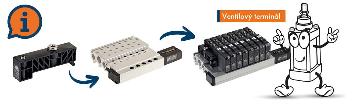
Once you have selected a valve or valves, they can be installed on a valve terminal - base plate for a better overview and schematic layout. By creating such a terminal or valve island, you also save maximum space and facilitate possible work for setup technicians of the production line or plant where the valves are needed. And if you have reached this point, installing valves on an island yourself, you are truly capable and we bow to your knowledge. Choosing the right valve is not easy, and customers often return valves to us because the choice was incorrect and the valve was able to perform the required function. Therefore, let us know anytime you are unsure about a decision.