


Summary:
- Correctly designing a compressor room depends on detailed determination of flow and pressure according to actual consumption.
- Also important are structural and spatial requirements, such as floor load capacity and controlled ventilation, which protect the equipment from overheating and vibration.
Basic requirements for a compressor room are a set of technical, structural and operational criteria that must be met for safe and economical operation of a compressor system in an industrial environment. A correctly designed compressor room ensures a stable supply of compressed air, minimizes energy losses and extends the service life of the equipment. This guide covers key areas from flow and pressure sizing through structural standards to the control of multi-compressor systems. It is based on Atlas Copco recommendations and IEC 61511 standards, so you will get an overview that you can directly apply when designing or modernizing a compressor room.
1. Basic requirements for a compressor room: flow and pressure as the starting point
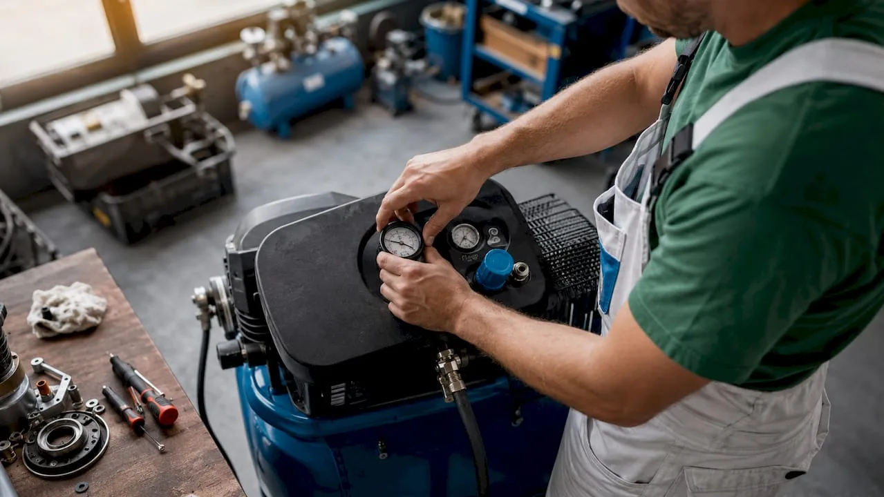
Correct design of a compressor room always starts with air flow (CFM) and working pressure (PSI or bar). These two parameters determine what compressor output is actually needed, and only from them is the power input in kW or HP derived. The opposite approach, i.e. selecting a compressor based on power without knowing actual consumption, leads to undersizing or oversizing of the system.
Atlas Copco recommends compiling a detailed list of all tools and applications with their CFM and PSI requirements. This list must include simultaneous operation of equipment, i.e. how many tools will be working at the same time and what their peak demand is.
Key steps in compiling technical requirements:
- List all points of use with their rated flow and pressure.
- Determine the simultaneity coefficient (not all equipment runs at the same time).
- Add a 10–20% reserve for future expansion.
- Include pressure losses in piping, filters and dryers.
Pressure losses are the most commonly underestimated factor. Atlas Copco points out that losses in dryers and filters can be significant enough that a compressor with a catalog-correct pressure fails to deliver the required pressure at the point of use. In practice, this means that if you need 6 bar at the point of use, the compressor must operate at 7 or 7.5 bar to cover the system losses.
Professional tip: When sizing, always start from the CFM and PSI requirements, and only then select the compressor power. This approach minimizes energy losses and prevents unnecessary oversizing.
Compressor power in kW is a supplementary parameter, not a starting point. Practical examples of compressor applications show that the same input power can correspond to very different flow rates depending on the compressor type and its efficiency.
2. Structural and spatial requirements for the compressor room
The compressor room space must meet specific structural and physical conditions. Having a free room is not enough. Flooring, ventilation, insulation, and vibration solutions are just as important as the selection of the compressor itself.
Floor load capacity and insulation
Industrial compressors are heavy equipment. For industrial compressors in containers, the floor is standardly reinforced to a load capacity of at least 1,000 kg/m². This value also applies as a default minimum for permanent compressor rooms in production halls. Insufficient floor load capacity causes vibrations that accelerate wear on joints and piping.
Insulation must meet fire resistance class A1 and include a 0.2 mm vapor barrier against condensation. Condensation in the structure of the compressor room causes corrosion of the structural elements as well as the equipment itself and shortens its service life.
Ventilation and cooling
| Parameter | Minimum requirement | Recommended value |
|---|---|---|
| Fresh air supply | Natural ventilation | Forced ventilation with louvres |
| Warm air exhaust | Opening near the ceiling | Fan with thermostat |
| Room temperature | Max. 40 °C | 20–30 °C |
| Air humidity | Max. 85% RH | Below 60% RH |
Compressors produce a large amount of waste heat. Without sufficient ventilation, the temperature in the compressor room quickly rises above the equipment's operating limits, triggering thermal protection and causing unplanned shutdowns.
Vibrations and noise
Compressors generate vibrations that are transmitted into the building structure and piping. Anti-vibration pads under the compressor are a basic measure. For larger installations, flexible joints at the compressor outlet and acoustic wall cladding are used. Noise in the compressor room commonly reaches 70–85 dB, so the space must be separated from workplaces with a requirement for lower noise levels.
Professional tip: Modular containerized compressor rooms from manufacturers such as CubeCont address load capacity, insulation, and ventilation as a whole. When expanding production, they save both time and costs, since the entire station can be relocated without construction work.
3. control of multi-compressor systems: lead and lag mode
Multi-compressor systems require a properly configured control system. Without it, compressors operate uncoordinated, wear unevenly, and consume more energy than necessary.
The principle of lead-lag control mode is that one compressor (lead) covers the base load and the other (lag) starts only when the lead compressor's capacity is exceeded. This arrangement extends the service life of both machines and reduces energy costs.
Typical setting parameters
| Parameter | Typical value |
|---|---|
| Lag compressor start delay | 30–60 s |
| Lag compressor stop delay | 60–120 s |
| Control pressure | 80–100 psig (5.5–6.9 bar) |
| Deadband | 10–20 psig (0.7–1.4 bar) |
Typical lead-lag mode settings specify a start delay of 30–60 s and a stop delay of 60–120 s. These delays prevent short cycling, which causes excessive wear on starting mechanisms.
Incorrect parameter settings lead to frequent compressor switching, increased wear, and higher energy consumption. Too narrow a deadband causes compressors to start and stop at short intervals, which is the most common cause of premature electric motor failure.
Safety shutdown
Safety features such as shutdown on high oil temperature, motor overload, or overpressure are mandatory under IEC 61511 and OSHA 1910.169 standards. These protections must be wired outside the PLC, i.e. directly in hardware, so that they function even in the event of control system failure.
Professional tip: Consult the compressor manufacturer or a service technician regarding deadband settings. Too wide a deadband causes pressure fluctuations in the network, too narrow a deadband wears out the compressors. The correct value depends on the air receiver volume and the nature of the demand.
Choosing the right compressor type for multi-compressor systems is described in the comparison of screw and piston compressors, which also presents the typical operating parameters of both technologies.
4. Compressed air distribution: planning and material quality
Compressed air distribution systems are part of the compressor room that most significantly affects the actual performance of the entire system at the points of use. Poorly designed distribution systems cause pressure losses, water condensation in the piping, and increased maintenance costs.
Quality compressed air distribution systems include the correct selection of materials, minimizing pipe lengths and pressure losses, and the integration of elements such as separators, filters, and air dryers. Each of these elements adds a pressure loss, which must be included when sizing the compressor.
Basic requirements for compressed air distribution systems:
- Pipe material: Certified pipes for compressed air (steel, aluminum, or plastic depending on pressure and environment). Poor-quality materials corrode and contaminate the air.
- Pipe diameter: Size for maximum flow with a reserve. Too narrow piping causes pressure losses even with a correctly selected compressor.
- Minimizing length: Shorter distribution systems mean lower losses. The compressor room should be located as close as possible to the main points of use.
- Accessibility for maintenance: Every filter, dryer, and separator must be accessible for regular inspection and replacement of consumables.
- Expandability: Design the distribution system with connections for future points of use. Additional drilling into pressurized piping is costly and risky.
- Pipe slope: Horizontal branches must have a slope of 1–2% in the direction of flow to drain condensate into the separators.
The integration of control systems and pressure monitoring in the distribution system allows for the early detection of air leaks. Leaks are the most common cause of unnecessary energy consumption in industrial compressor rooms. Continuous pressure monitoring at key points in the network reveals a drop that signals a leak or a clogged filter.
When selecting an industrial compressor, it is also advisable to take the planned distribution system into account, as the type of compressor affects air quality and, consequently, the filtration requirements in the network.
Key takeaways
A properly designed compressor room requires the simultaneous fulfilment of technical, structural and operational requirements, with the starting point always being the determination of flow and pressure according to the actual needs of the operation.
| Point | Details |
|---|---|
| Flow and pressure as a basis | Size the compressor based on CFM and PSI, not on power in kW. |
| Pressure losses in the system | Include losses in dryers and filters in the calculation, otherwise the compressor will not deliver the required pressure. |
| Construction standards | Floor min. 1,000 kg/m², class A1 insulation, 0.2 mm vapour barrier and forced ventilation are basic conditions. |
| Lead-lag system control | Set a delay of 30–60 s for starting and 60–120 s for stopping the following compressor. |
| Safety protection | Shutdown on oil overheating, motor overload, and overpressure must be wired independently of the PLC. |
Lessons from practice: what gets overlooked most often in projects
I have worked with compressor systems for many years, and I repeatedly see the same mistakes. Technicians pay attention to selecting the compressor but underestimate the distribution system. The result is that a new 11 kW compressor fails to deliver even 5 bar at the end of 80 metres of piping, because no one accounted for the losses in an outdated filter and piping that is too narrow.
The second most common mistake is ventilation of the compressor room. I have seen installations where the compressor was placed in a closed room without a supply of fresh air. The thermal protection would trip every summer, and the technicians considered it a fault of the compressor. The cause was in the room, not in the machine.
The third overlooked area is safety shutdowns in multi-compressor systems. Many installations rely solely on the PLC, without hardware safeguards. If the control system fails, nothing then stops a compressor operating outside safe parameters.
I recommend starting every compressor room project with a detailed analysis of consumption, walking through the physical space with measurements, and only then selecting the equipment. The energy savings achieved through proper sizing and system setup will pay for themselves within two years. The topic is covered in more detail in the guide to energy savings with a compressor, which includes specific examples from manufacturing operations.
— Zdeněk
Kompresory-vzduchotechnika will help you with the design and equipment
Kompresory-vzduchotechnika offers a complete range for the construction and operation of compressor rooms. From SCR screw compressors for industrial operation, through pressure vessels of 270–2,000 l, to certified pipes for compressed air distribution using the push-in system.
The Kompresory-vzduchotechnika team provides technical consultations on equipment selection, system sizing, and distribution planning. If you are working on a new compressor room or modernizing an existing one, contact us directly through the website. We will advise you on selecting the compressor, air tank, and air treatment accessories, for both industrial and construction applications.
Frequently Asked Questions
What are the basic requirements for a compressor room?
Basic requirements for a compressor room include proper sizing of flow and pressure, floor load capacity of min. 1,000 kg/m², forced ventilation, class A1 insulation, and safety shutdown according to IEC 61511 standards.
How to select a compressor for an industrial compressor room?
Compressor selection begins with compiling a list of consumption points with CFM and PSI requirements, adding pressure losses in the system, and adding a 10–20% reserve for future expansion.
What pressure losses must I include in the compressor room design?
The calculation includes losses in dryers, filters, separators, and distribution piping. Atlas Copco states that these losses can be significant enough that the compressor must operate 1–1.5 bar above the required pressure at the consumption point.
How to set up lead and lag compressor control mode?
Set the start delay of the lag compressor to 30–60 s, the stop delay to 60–120 s, and the dead band to 10–20 psig. These settings minimize wear caused by short cycling.
What safety features are mandatory in a compressor room?
Hardware shutdowns for high oil temperature, motor overload, and overpressure are mandatory. According to IEC 61511 and OSHA 1910.169 standards, this protection must be wired outside the PLC so that it functions even in the event of a control system failure.
Recommended
- Factors for selecting an industrial compressor: a 2026 guide - Kompresory-Vzduchotechnika.cz
- A list of safety rules for working with a compressor in automotive 2026 - Kompresory-Vzduchotechnika.cz
- What is Cyclic Compressor Operation: Guide 2026 - Kompresory-Vzduchotechnika.cz
- Saving energy with a compressor: an expert guide 2026 - Kompresory-Vzduchotechnika.cz