

BLOG
List of articles


Freezing of condensate in the compressed air distribution system: what to do immediately
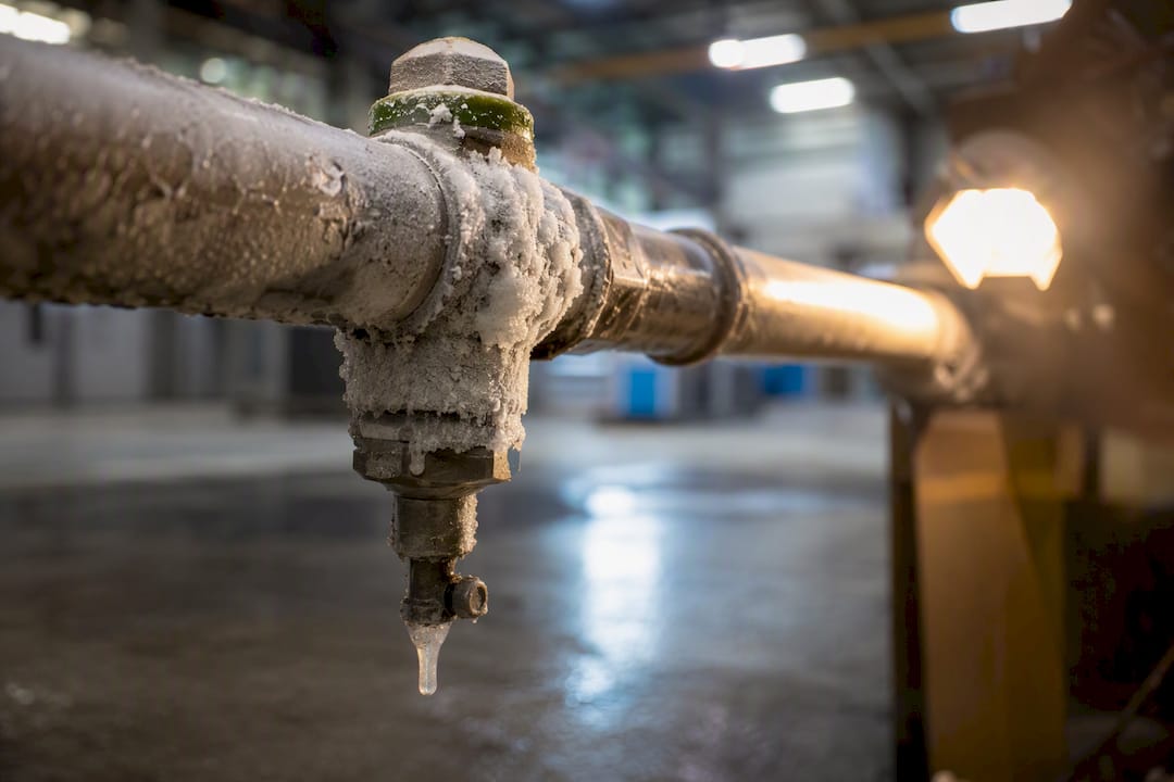
You can solve condensate freezing in the distribution system with three steps: set the pressure dew point as a monitored parameter, verify that condensate drains are actually removing water, and insulate or actively heat pipe sections in unheated areas. Without these three measures, the pipework can become blocked by an ice plug without warning during frost. Air quality is described by the ČSN ISO 8573-1 standard, and for more serious problems it is worth consulting a service company such as Kompresory-vzduchotechnika.
In short:
- If the temperature at the coldest points of the distribution system is lower than the set PDP, there is a risk of freezing and an ice plug forming in the pipework.
- For outdoor or unheated piping, it is necessary to use a dryer with a deeper pressure dew point margin, for example an adsorption dryer, and install a heating cable.
- Condensate drains should be correctly sized, regularly inspected, and fitted with insulation or heat tracing to prevent freezing.
- Measuring the pressure dew point at strategic points provides early warning of freezing risk and facilitates preventive maintenance.
- Repairing a burst pipe is a short-term solution; in the long term, it is worth investing in insulation, a more powerful dryer, or a system with an appropriate PDP.
Contents
- Why condensate forms in piping and when there is a risk of freezing
- Where to measure the pressure dew point and how to set up warnings
- How to size the dryer and filtration for freezing operating conditions
- Condensate drains: installation, slope, and inspection intervals
- Insulation and heating of piping in exposed sections
- Operating procedures for winter mode
- How to safely thaw a frozen section of the distribution system
- When a repair is not enough: operational decisions and the economics of prevention
- How Kompresory-vzduchotechnika can help you reduce the risk of freezing
- Recommended technical resources and standards
- Frequently asked questions
Why condensate forms in piping and when there is a risk of freezing
Compressed air contains water vapour, which the compressor draws into the system from the intake air. Once the air is compressed and subsequently cooled, the vapour condenses into liquid water. This is governed by the pressure dew point (PDP), the temperature at which, at a given operating pressure, water vapour begins to turn into condensate. PDP is a different quantity from the atmospheric dew point, which describes the behaviour of air at normal pressure, and must therefore not be confused with it when designing a system.
The higher the overpressure in the piping and the lower the surface temperature of the pipe, the sooner the vapour will condense into droplets. In practice, this means that critical points are not random:
- outdoor sections of piping and connections without thermal insulation,
- the lowest points of the network, where water accumulates by gravity,
- branches and dead-end sections with low air flow,
- condensate drain outlets leading into unheated shafts.
It is precisely at these points that an ordinary drop of water turns into an ice plug, which restricts or completely stops the flow of air to the production machines.
Where to measure the pressure dew point and how to set alarms
It makes sense to place the PDP sensor where the quality of the air for the entire network or for a sensitive part of production is determined. As standard, it is installed:
- at the dryer outlet, to verify that the equipment actually achieves its declared performance,
- on the main distribution branches before splitting into sub-circuits,
- at critical consumers, where moisture in the air endangers production quality or operational safety.
For long-term operation in freezing conditions, polymer capacitive sensors have proven more reliable than older Al2O3-based sensors. Polymer sensors withstand condensate and oil vapours better and reliably measure even deep dew points around minus 60 °C, which older technology often could not manage without frequent calibration.
Professional tip: Set the alarm according to the purpose of the air, not universally. For common pneumatic drives, a PDP within the temperature range specified by the dryer manufacturer is usually sufficient, but for sensitive processes where moisture must not affect product quality, a significantly lower PDP matching the air quality requirements is recommended.
Continuous PDP monitoring also enables predictive maintenance: you can replace the filter or dryer before moisture penetrates the network and causes damage to tools and valves.
How to size the dryer and filtration for freezing operating conditions
The dryer must provide a margin against the coldest point in the distribution system, not against the average temperature in the hall. The practical rule is: set the target PDP significantly lower than the lowest expected pipe temperature to minimize the risk of condensation and freezing. So if a pipe runs through an outer wall where the temperature drops to minus 10 °C in January, you need a dryer with a PDP around minus 20 to minus 30 °C, not a refrigeration unit designed for +3 °C.
The choice between dryer types depends on this goal:
- a refrigeration (condensation) dryer covers standard indoor distribution with a PDP around +3 °C,
- an adsorption dryer can achieve the deep dew points needed for outdoor runs and freezing halls.
Even the best dryer won't solve anything if condensate isn't drained from the pipework. A filter capturing solid particles and a coalescing separator that strips oil droplets from the air stream should therefore be installed before the drain. Without this filtration, drains clog faster and their valves seize up in frost in a position where water remains inside the pipe.
Professional tip: Before the season, compare the actually measured PDP with the value stated on the dryer's nameplate. A deviation of more than a few degrees indicates worn sorption media or a leak that is worth addressing before the frosts arrive.
Condensate drains: installation, slope and inspection intervals
A non-functioning drain is the most common cause of freezing in plants that otherwise have a correctly sized dryer. You can choose between several principles, each with different weaknesses:
- Manual drain requires an operator who opens the valve regularly. Without operator discipline, water remains in the piping.
- Timer drain discharges condensate at fixed intervals regardless of how much water has actually accumulated, so at higher humidity it is insufficient and at low humidity it wastes air.
- Float drain responds to the water level, but the strainer and mechanism become clogged with deposits and oil.
- Electronic (capacitive) drain discharges condensate according to actual need and is usually the most reliable choice for operations with variable humidity.
Regardless of type, the same installation rules apply: the line to the drain must have sufficient slope, the trap must be permanently filled with water, and all joints must be sealed, otherwise it draws in air and the mechanism falsely signals an empty pipe. In unheated spaces, the trap should have insulation or a heating cable, otherwise it will freeze first.
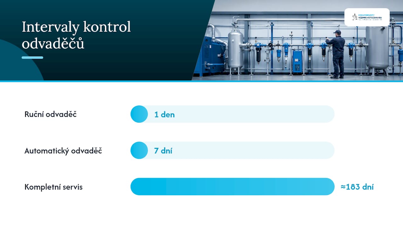
Inspection intervals vary by device type: manual drains should be checked daily, automatic ones weekly, and a complete service including the strainer and valve should be performed at least twice a year. More on selecting and installing individual types can be found in the guide to condensate drains.
Insulation and heating of piping in exposed sections
Passive insulation handles most internal distribution, where the temperature does not drop toward freezing anyway. However, once the piping runs through an exterior wall, roof, or unheated hall, insulation alone is not enough, because it only slows heat loss, it does not stop it. That's where a heating cable wound along the pipe or an electric jacket with a thermostat belongs, keeping the pipe surface above freezing even during prolonged frost.
When installing a heating cable, several principles apply:
- run the cable along the underside of the pipe, where condensate accumulates first,
- protect the electrical connection against moisture with an enclosure rating of at least IP65,
- include traps and drains in the heated route, not just straight sections of piping.
Professional tip: The cost of heating cable and insulation pays for itself at the first shutdown it prevents. An hour of production downtime due to a blocked pipeline usually exceeds the cost of heating the entire risk branch for a season.
Operating procedures for winter mode
Time-based dryer switching is unreliable in frost because it does not respond to actual air humidity. Better results are achieved by control based on the actual dew point, known as dew point-dependent switching, which activates the dryer only when the PDP actually requires it.
The winter operating plan includes:
- responding to a PDP alarm within the same shift, not the next day,
- recording every intervention on drains and the dryer for subsequent trend review,
- a pre-season test of all drains and heating cables before the first frosts.
This approach also saves energy, as the dryer does not run unnecessarily at full power when the PDP indicates that the air is sufficiently dry.
How to safely defrost a frozen section of the pipeline
Detecting a frozen blockage usually starts with a pressure drop downstream of the given section or a silent outlet where escaping air used to hiss before. Defrosting procedure:
- Depressurize the affected section and isolate it from the rest of the network so that sudden release of the blockage does not create a pressure spike.
- Check the sensors and drains in the surrounding area, as an ice blockage is often related to a previous drainage fault.
- Apply local controlled heating, for example with a hot air gun or an attached heating cable, and increase the temperature gradually.
- After thawing, slowly re-pressurize the section again and verify that water is actually draining out.
Open flame on piping has no place here, as it risks damaging seals and igniting oil residues. Likewise, abrupt over-pressurizing of the frozen section or rough mechanical removal of the plug is not advisable, as both methods risk bursting the pipe or damaging fittings.
When repair is not enough: operational decisions and the economics of prevention
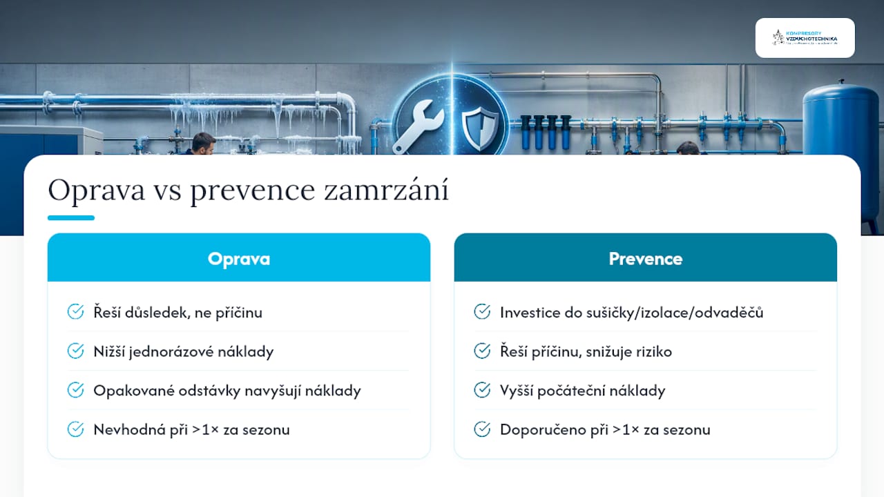
Repairing a burst pipe or replacing a damaged valve addresses only the consequence, not the cause. If freezing recurs at the same spot more than once per season, it is a signal that the system needs investment in a dryer, insulation, or higher-quality drains, not another patch. A one-off repair looks cheaper on paper, but repeated production stoppages quickly outweigh it.
A signal to order a professional intervention is also a situation where the measured PDP does not match the dryer's parameters over the long term, or when the drains need cleaning more often than the schedule indicates. In such a case, it makes sense to have a professional energy audit of the distribution system carried out, which will reveal where the system is losing performance and where the risk of freezing arises. A professional audit is available for facilities where prevention pays off more than repeatedly firefighting problems.
— Zdeněk
How Kompresory-vzduchotechnika helps you reduce the risk of freezing
Kompresory-vzduchotechnika is an alternative to random repairs for your operation: instead of addressing individual ice plugs, it delivers a complete air treatment solution that eliminates the risk of freezing at the source. The offer includes compressed air treatment units up to 18 bar for dimensioning the PDP according to your coldest route, as well as a filtration program according to ISO 8573, which protects condensate drains from clogging.
In addition to selling equipment, Kompresory-vzduchotechnika also offers installation, inspections, and service interventions described in the services overview. If condensate freezing in your distribution system keeps recurring, or if you are unsure about correctly sizing the dryer before winter, order a technical inspection of the system and have a specific solution calculated for your network.
Recommended technical resources and standards
- A detailed guide on selection and installation can be found in the article on types of condensate drains.
- Practical sensor placement is described in the guide on measuring air pressure.
- The legal aspects of handling condensate are summarized in the article on laws for compressor operators.
Frequently Asked Questions
What is the pressure dew point and why does it determine freezing?
The pressure dew point is the temperature at which water vapor begins to condense into liquid at the operating air pressure. The lower you keep it below the freezing point in the coldest section of the piping, the lower the risk of an ice plug.
How often should condensate drains be checked in winter?
Manual drains should be checked daily, automatic ones weekly, and a complete service including the strainer should be performed at least twice a year, with emphasis on checking before the onset of frost.
What PDP should be chosen for outdoor piping?
The target PDP should be 10 to 20 °C lower than the lowest expected piping temperature, which for outdoor routes in winter usually means choosing an adsorption dryer instead of a refrigeration dryer.
Is it safe to thaw frozen piping with an open flame?
No. An open flame damages seals and risks igniting oil residues. The safe method is controlled local heating with gradual repressurization after depressurizing the section.
Who can help with auditing and servicing the piping system against freezing?
Technical consulting, installation of insulation and heating cables, as well as servicing of drains and dryers, including an energy audit, can be arranged through specialized companies for facilities with a recurring freezing problem.
Recommended


PDP +3 °C: what to install and where against corrosion in the air distribution system
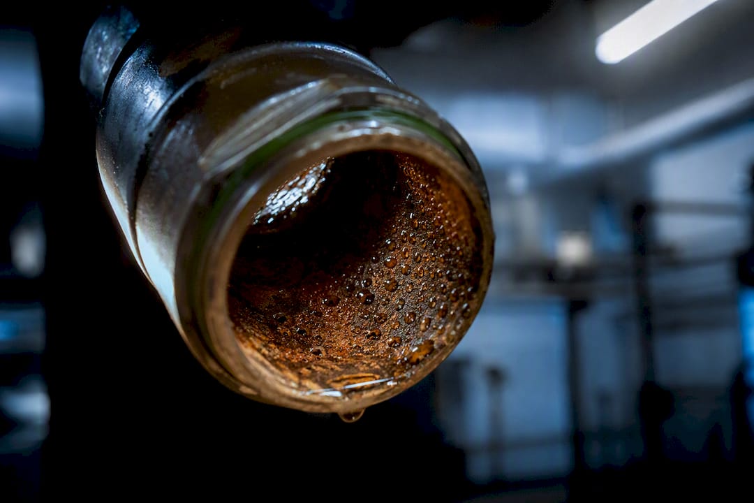
Corrosion in the air distribution system primarily arises from the condensation of moisture inside the piping. The fastest defense is to install a suitable dryer together with an automatic condensate drain, which captures water before it starts attacking the pipe walls. Regular inspections according to recognized standards and the choice of a durable piping material will then keep the risk to a long-term minimum.
In short:
- Corrosion in the air distribution system arises mainly from the condensation of moisture as the air cools, which increases pressure losses and causes equipment wear.
- The most effective prevention is the correct choice of dryer and automatic condensate drain, while stainless steel or plastic pipes reduce the risk of corrosion.
- Checks for rust and other signs of corrosion should be carried out regularly, for example weekly or monthly, and an annual camera inspection helps detect hidden damage.
- Measuring the pressure dew point allows for a more precise evaluation of the degree of condensation and optimization of the drying parameters, significantly reducing the risk of corrosive processes.
- Long-term maintenance includes checking slopes, replacing filters, and, where necessary, replacing the piping material to minimize the risk and effects of corrosion.
Contents
- What is corrosion in compressed air distribution and why it occurs
- How corrosion manifests in operation and what its effects are
- Main causes and risk factors of corrosion formation
- Prevention: technical measures, equipment and design recommendations
- Maintenance, inspection and standards: specific intervals and records
- Measuring dew point (PDP) and monitoring for predictive maintenance
- What to do when you find corrosion: immediate and long-term steps
- Author Zdeněk's experience: most common mistakes and proven solutions from practice
- Solutions for corrosion prevention from Kompresory-vzduchotechnika
- Frequently Asked Questions
What is corrosion in compressed air distribution and why it occurs
The air drawn in by the compressor contains water vapor. During compression, both temperature and pressure rise, but as soon as the air cools down in the piping, the vapor begins to condense into liquid water. This liquid settles in slopes, elbows, and low points of the network, where it gradually attacks the metal.
The key parameter is the pressure dew point (PDP), the temperature at which vapour in a pressurised system begins to condense. The higher the PDP, the higher the risk that water will appear in the piping at normal operating temperatures. Corrosion then does not remain merely a cosmetic defect. It roughens the internal surface of the pipes, which increases friction of the flowing air and thus pressure losses (Δp) throughout the network. The compressor must operate at higher output to deliver the same volume of air to the end of the distribution system.

How corrosion manifests in operation and what its effects are
Rust in the piping can be detected even without dismantling the system. The most common signs can be found directly on the end elements of the network.
- Rust stains or rust-coloured condensate at the outlet of the drains.
- Metal particles captured in the filter element, which becomes clogged faster than usual.
- Increasing pressure drop between the compressor room and the end consumer with unchanged consumption.
- Premature wear of seals and cylinders in pneumatic tools.
Corrosion can significantly shorten the service life of equipment, because released rust particles act as an abrasive material inside valves and cylinders. The result is a chain of failures, where one neglected section of piping gradually damages expensive end equipment. Besides the costs, the safety risk also increases: corrosion of the internal walls of pressure vessels and air tanks often remains invisible for a long time, because the weakening occurs from the inside, not on the surface where a technician would notice it during a routine inspection.
Main causes and risk factors of corrosion formation
Most cases of corrosion are caused by a combination of several operational errors, not a single obvious fault.
- Insufficient drying or filtration, which leave the system's PDP too high for the given application.
- Stagnation of air in dead-end sections, water traps, and poorly designed slopes where condensate accumulates.
- Unsuitable pipe material or damaged surface treatment that exposes bare metal.
- Neglected condensate drainage, whether manual or due to a malfunctioning automatic drain.
Professional tip: Before you start replacing piping, check the slopes and lowest points of the network. Most corrosion we encounter arises in the same section where a long-neglected water pocket repeatedly fills and empties.
Prevention: technical measures, equipment and design recommendations
Effective corrosion prevention in air distribution relies on a combination of drying, moisture separation and proper material selection, ranked according to where the greatest risk arises.
- A dryer as the first line of defense. A refrigerant dryer is sufficient for common workshop and production operations with a target PDP of around +3 °C. An adsorption dryer is necessary where critical applications are involved, such as food processing, pharmaceuticals, or outdoor distribution exposed to frost, since it achieves a PDP in the range of −40 °C to −70 °C.
- A separator or cyclone right after the compressor. It captures bulk moisture and oil droplets before they move further into the network, reducing the load on subsequent filtration.
- An automatic condensate drain at every low point and after every dryer, so water doesn't accumulate unattended.
- Coalescing filtration to capture oil aerosols that would otherwise settle on the walls and promote corrosion processes.
The choice of pipe material determines how quickly even residual moisture turns into a problem. Stainless steel and aluminum significantly reduce susceptibility to internal corrosion compared to standard black steel. Modern pipes for compressed air distribution made of aluminum or quality plastic also offer lower pressure drop, albeit with a limitation on maximum operating pressure that must be respected at higher pressure levels.
| Measures | When to use | Main benefit |
|---|---|---|
| Refrigerant dryer | Standard operation, workshops, production | PDP reduction to approx. +3 °C |
| Adsorption dryer | Critical and frost-resistant applications | PDP down to −70 °C |
| Cyclone separator | Immediately after the compressor | Capturing bulk moisture and oil |
| Automatic drain | Low points, dryer outlet | Continuous condensate drainage |
| Coalescing filter | Upstream of sensitive equipment | Removal of oil aerosols |
When designing a new line, remember the slopes towards drain points, inspection openings for camera inspection, and easy access to drains. For details on calculating pipe diameter and slope, see the separate compressed air distribution sizing procedure.
Maintenance, inspection and standards: specific intervals and records
The maintenance plan for air distribution systems is based on two technical standards. ČSN EN 15780 defines three cleanliness classes for ventilation systems and recommends a procedure: first visual assessment, then contamination measurement. ČSN ISO 8573-1, on the other hand, classifies compressed air quality according to particle, water and oil content, and therefore serves as the reference value against which measurement results are compared.
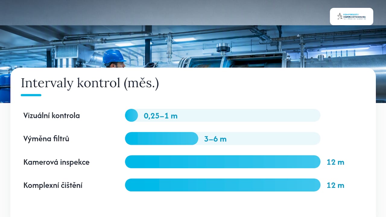
- Quick visual check of critical sections: weekly to monthly.
- Detailed annual inspection with camera inspection of the internal surface of piping and pressure vessels.
- Replacement of filter cartridges according to the degree of contamination, usually every three to six months.
- In industrial operations, complete cleaning of the distribution system at least once a year has proven effective.
Professional tip: Photographically document each inspection, ideally the same section at each check from the same angle. Comparing the images over time will show the rate of corrosion progress much more accurately than individual isolated observations.
The inspection record should include the measured pressure dew point, the date of the last filter change, and photographic documentation of the internal condition. This data then serves as a basis for deciding whether the section should just be cleaned or already replaced.
Dew point (PDP) measurement and monitoring for predictive maintenance
PDP measurement is the only reliable way to assess the risk of condensation in a pressurised system. This is because relative humidity (RH) distorts the actual condition in a pressurised environment, as it is measured differently than in atmospheric air. The PDP sensor is placed after the dryer and, if applicable, also at the end of the longest or most critical branch of the distribution system.
| Application type | Target PDP |
|---|---|
| Standard workshop operation | approximately +3 °C |
| Moisture-sensitive production | +3 °C |
| Critical and frost-resistant applications | −40 °C to −70 °C |
Controlling dryers based on the currently measured PDP, rather than on a fixed time cycle, reduces energy consumption while also better protecting the network against an unexpected rise in moisture. An alarm set just above the target PDP value gives the technician time to intervene before the first drops appear in the piping.
What to do if you find corrosion: immediate and long-term steps
Corrosion found requires a quick but structured approach, not a panic-driven replacement of the entire section.
- Isolate the affected section immediately, drain the accumulated condensate, and if operations allow, redirect the air flow via another route.
- Perform a visual and camera inspection to estimate the depth of the attack, and decide whether a local repair is sufficient or whether the section needs to be replaced.
- For pressure vessels and air receivers, consult the extent of damage with a specialist, as a weakened vessel wall represents a safety risk. The rules for draining condensate from such vessels are summarized in the overview condensate from compressors and Czech Republic law.
- In the long term, consider changing the piping material, adjusting the slopes, or adding a dryer so that the same problem does not recur.
Experience of the author Zdeněk: the most common mistakes and proven solutions from practice
In practice, corrosion most often returns where the automatic drain was omitted to save money or replaced with manual draining, which is then forgotten. Aluminum modular piping combined with regular PDP measurement and an advisory service you can turn to before the problem solves itself at your expense has proven effective.
— Zdeněk
Corrosion prevention solutions from Kompresory-vzduchotechnika
Kompresory-vzduchotechnika offers specific equipment that addresses corrosion at the point where it originates, not after the damage has occurred. Compact Combibloc compressed air treatment units combine drying, filtration, and moisture separation into one compact unit for operations up to 16 bar, so you don't have to assemble a system from several separate components.
For low points in the network, we recommend familiarizing yourself with the overview condensate drains, their types, and installation, which will help you choose the right type according to the size of the operation. If you are not sure exactly where in your network the risk of corrosion arises, or if you need to measure the current pressure dew point, contact Kompresory-vzduchotechnika and arrange a consultation or service intervention tailored directly to your operation.
Frequently Asked Questions
How does corrosion manifest in the air distribution system?
Most commonly by a rusty discoloration of the condensate, metal particles in filters, a faster-rising pressure differential, and premature wear of pneumatic tools.
How to prevent corrosion in the compressed air distribution system?
The most effective approach is a combination of a dryer, a separator, a coalescing filter, and an automatic condensate drain, supplemented by regular inspection according to ČSN EN 15780.
What is the difference between a refrigerant dryer and an adsorption dryer?
A refrigerant dryer achieves a pressure dew point of around +3 °C and is sufficient for standard operation, while an adsorption dryer drops as low as −70 °C and is necessary for critical or frost-resistant applications.
How often should the air distribution system be checked for corrosion?
Inspect critical sections visually on a weekly to monthly basis, and carry out a detailed inspection with camera inspection and PDP measurement at least once a year.
Why is the pressure dew point more important than relative humidity?
Relative humidity in a pressurized system distorts the actual risk of condensation, while PDP directly indicates the temperature at which water will start condensing in the piping.
Recommended


Save tens of thousands: a compressor service contract for companies

Yes, a service contract for a compressor usually increases equipment availability, reduces unexpected downtime and stabilises operating costs. The company pays a predefined amount and receives regular inspections, spare parts and emergency assistance without having to deal with each intervention separately. A side effect is usually lower energy consumption and longer equipment service life. For key machines, it is worth having an offer and an energy audit prepared by a specialist.
In brief:
- A service contract for a compressor increases equipment availability and enables regular checks that prevent faults and shorten unplanned downtime.
- In addition to the basic inspection package, it may offer full service, which includes preventive replacements and energy optimisation, often a condition for the manufacturer's warranty.
- The greatest savings and lower risk of failure lie in regular leak checks, monitoring of operating parameters and early detection of leaks, which reduces both energy and repair costs.
- When choosing, emphasis should be placed on the guarantee of immediate intervention, availability of spare parts and clearly defined conditions in the offer, not just on the price.
- In operations where the compressor drives a production line, full service is often more economically advantageous than basic checks, as it minimises the risk of costly unplanned downtime.
Contents
- What a compressor service contract includes in practice and what benefits it brings
- Main benefits of a compressor service contract
- How a service contract reduces operational risks and costs
- How to choose a compressor service contract and what to ask the supplier
- Maintenance intervals that a service contract should cover
- Why we recommend service contracts in practice
- How Kompresory-vzduchotechnika.cz can help you with a service contract
- Useful resources and documents
- Frequently asked questions
What a compressor service contract includes in practice and what benefits it brings
A compressor service contract combines several types of activities into one package. Depending on the scope, it ranges from basic inspection up to what is known as full service, where the supplier takes over practically all responsibility for the operation of the equipment.
A standard contract includes:
- scheduled inspections at fixed intervals,
- preventive work (oil change, filters, leak-tightness check),
- spare parts included in the price or at a discounted rate,
- an assistance line for reporting faults outside normal working hours,
- the option to borrow a replacement unit during a longer shutdown,
- recommendations for energy-related system upgrades.
The difference between the individual levels is fundamental. Inspection means only a condition check without intervention. Maintenance already covers the replacement of consumables. Full service (for example, the model offered by KAESER) combines both with a guarantee of availability and often also energy optimization. A contract is moreover often a condition for maintaining the manufacturer's warranty, since it is often tied to the use of original parts and compliance with the prescribed intervals.
Main benefits of a compressor service contract
The biggest benefit of a service contract is measurable directly in operational figures. It's not about abstract "peace of mind," but about concrete savings and a lower risk of production downtime.
Professional tip: Before signing the contract, calculate how much your last unplanned compressor shutdown cost you. This figure is the best argument for negotiating terms with the supplier.
The main benefits of a service contract include:
- higher equipment availability — regular inspections detect wear before it causes a failure,
- lower energy consumption — clean filters and eliminated leaks reduce energy losses, which are one of the most common sources of waste in compressed air systems,
- longer compressor lifespan — adherence to maintenance intervals protects the compression block and motor,
- higher residual value — equipment with documented service history sells better and is assessed more favourably when buying it back,
- reduced risk of insurance or safety complications — compliance with standards and regular inspections limit operational risks.
Leak detection is one of the measures that pays for itself quickly. A leak in the air distribution system works like a tap that's left running all year round, and a service technician will find it during a routine inspection sooner than operating staff would. The combination of lower energy consumption and less costly repairs then translates directly into the cost per unit of compressed air produced, an indicator that makes sense to track even for small operations.
How a service contract reduces operating risks and costs
The benefit of a service contract isn't just based on paper promises. It involves specific mechanisms that a service technician carries out repeatedly and systematically.
- Planned oil and filter changes according to prescribed intervals, usually around 500 operating hours for oil.
- Checking the tightness of distribution lines and fittings, where the greatest energy losses occur.
- Monitoring operating parameters — pressure, temperature and humidity, which signal an approaching problem before a failure occurs.
- Remote diagnostics, thanks to which the service partner reacts to a deviation in the data before it's noticed by on-site staff. The topic is covered in more detail in compressor diagnostics for efficient operation.
- Fast availability of parts from stock and the possible loan of a replacement unit if the repair takes longer.
Return on investment in the contract is calculated simply: you compare the estimated cost per hour of downtime (lost production, overtime, penalties for late delivery) with the annual price of the contract. In an operation where the compressor powers the entire production line, the contract often pays for itself after avoiding just one serious failure. You can find the calculation of compressor operating costs broken down in the 7-day audit of compressor operating costs.
How to choose a compressor service contract and what to ask the supplier
When comparing offers, don't just look at the price per inspection. The difference between a cheap and an expensive contract usually lies in what is "below the line" and what only becomes apparent at the first failure.
Key criteria for selection:
- guaranteed response time (SLA) expressed in hours, not just "as soon as possible,"
- coverage of wearing parts and clearly stated exceptions,
- supplier's spare parts stock and actual availability of the specific model,
- transparent price list without hidden surcharges for call-outs or work outside business hours,
- the option to borrow a replacement unit during a longer repair,
- references and experience with the given type and output of compressor.
Specific questions worth asking: What exactly does the contract cover and what is excluded from it? What is the guaranteed delivery time for spare parts if they are not in stock? Is it possible to schedule service interventions outside shifts so they don't disrupt production? And how are situations handled when a failure exceeds the agreed repair time? The answers to these questions often reveal more than the price itself in the offer.
Maintenance intervals that a service contract should cover
A quality contract mirrors the real needs of the machine, not a universal template. The following overview serves as a reference framework for comparing the offered scope of services.
| Interval | Typical task | Who usually performs it |
|---|---|---|
| Daily | Checking oil level, draining condensate | Operating personnel |
| Weekly | Checking and, if necessary, replacing air filters | Operating personnel |
| Monthly | Checking belts, tightness of joints and piping | Operating personnel / technician |
| Every 500 h or 3 months | Oil and oil filter change | Service technician |
| Annually | Complete service inspection, compression block check | Service technician |
Operating personnel typically carry out daily and weekly checks, while specialized tasks are the responsibility of a service technician. A good contract aligns these two levels so that downtime for annual servicing is scheduled outside peak production periods. Common mistakes in operating a compressor that disrupt this alignment are described in the article on the most common mistakes when using compressors.
Why we recommend service contracts in practice

A service contract does not pay off equally for everyone. Where a compressor powers a single auxiliary pneumatic gun, a basic inspection once a year is sufficient. Where compressed air powers an entire production line and an hour of downtime costs tens of thousands of crowns, full service is the obvious choice regardless of the price difference compared to the basic package.
From real service interventions, we repeatedly see one pattern: companies that underestimated the contract end up dealing with failures at the worst possible moment, on a weekend or in the middle of an order with a deadline. Loaning a replacement unit and a parts stock for contract partners practically eliminate this scenario.
**
How Kompresory-vzduchotechnika.cz can help you with a service contract
There are specific alternatives to random interventions without a contract: technical support, a spare parts stock, energy audits, and installation of new units all under one roof.
If you operate a compressor that production depends on, it is worth having an energy audit carried out first and only then designing the scope of the service contract, not the other way around. The offer also typically includes an assessment of treated air quality, which follows on from the compressed air filtration program according to ISO 8573. Corporate customers can also take advantage of registration for special prices and faster processing of inquiries. For specific solutions, including compressed air treatment units up to 18 bar, request a quote via the product page with technical parameters and arrange a non-binding consultation.
Useful resources and materials
For a deeper understanding of the topic, we recommend materials from Atlas Copco on compressor energy efficiency, an overview of maintenance intervals from HQCompresor, and information on maintenance contracts from manufacturers ALMiG and KAESER, which describe the individual levels of service packages.

Frequently Asked Questions
What is the service life of a compressor?
The service life of a piston compressor typically ranges from ten to fifteen years of operation, while that of a screw compressor tends to be longer, provided the prescribed oil and filter change intervals are observed. Regular maintenance under a service contract is one of the strongest factors that extends this lifespan.
What is the service life of a screw compressor?
A screw compressor, when properly maintained, usually lasts longer than a piston compressor, as it has fewer mechanically worn parts in direct contact. Regular oil changes approximately every 500 operating hours and inspection of the compression block during the annual check-up are particularly decisive.
What kind of oil goes into a compressor?
Oil specified directly by the manufacturer for the given type of machine is used in a compressor, usually a synthetic or semi-synthetic oil with properties resistant to high temperatures and pressure. Using the wrong oil can jeopardize both the warranty and the function of the compression block, which is why a service contract with original parts eliminates this risk.
What is better, a compressor or a turbo?
A compressor and a turbocharger address different tasks and are not interchangeable alternatives: a stationary industrial compressor produces compressed air for pneumatic tools and manufacturing processes, while a turbocharger supplies pressurized air to a vehicle's combustion engine. The question of "which is better" therefore depends on the problem you're solving, not on a universal answer.
Is a service contract worthwhile even for a smaller workshop?
Yes, if a compressor failure stops even a single key operation, even a smaller workshop will save on predictable costs and faster parts availability. For operations with minimal load, a basic contract with an annual inspection may be sufficient instead of full service.
Recommended

Pressure fluctuations in the system: quick fixes and permanent solutions for operations

Pressure fluctuation in a compressed air system means irregular variations, drops, or short-term overpressures in the piping between the compressor and the consumers. For the first 15 minutes, address it with three steps: check the differential pressure on the filters, verify condensate drainage from the separators, and check the pressure reducing valve setting at the problematic outlet.
In brief:
- If pressure fluctuation recurs even after filter replacement and a leak check, it is advisable to carry out an energy audit of the system.
- Undersized piping and incorrect selection of pipe diameter can cause significant pressure fluctuations, which must be correctly designed.
- Clogged filters, separators, and leaks are the main causes of persistent pressure deficits in the system.
- Quick diagnostic steps include installing permanent pressure gauges, shutoff tests, and monitoring the system's response, which will reveal the source of the fluctuation within one shift.
- Regular maintenance, including checking filters, drains, and couplings, is key to long-term prevention of pressure problems.
Contents
- Main technical causes of pressure fluctuation
- How to quickly and systematically diagnose pressure fluctuation
- Quick measures that often solve the problem during the same shift
- Permanent solutions for stable pressure in the distribution system
- A maintenance program that detects pressure fluctuations before production does
- Practical experience: when to solve it yourself and when to call service
- Solutions for pressure fluctuations, from air treatment to service intervention
- Frequently asked questions
Main technical causes of pressure fluctuations
Most cases of pressure fluctuations have one of five recurring causes. Identifying yours is the first step toward repair, not toward replacing the compressor.
- Undersized piping. Pressure loss increases exponentially with flow rate, so even a slight underestimation of pipe diameter when expanding production will cause noticeable pressure fluctuations at the end of the branch. Atlas Copco recommends keeping the pressure drop in main distribution lines at a maximum of 0.1 bar relative to the furthest point of consumption.
- Clogged filters and separators. A clogged filter element or an overfilled oil separator can by themselves cause an immediate pressure drop of a significant value, which can reach up to several bars.
- Leaks in the distribution system. A single leak at a fitting may seem insignificant, but dozens of small leaks in an older distribution system add up and manifest as a persistent pressure deficit at peak demand.
- Compressor pulsation and lack of accumulation. A piston compressor delivers air in pulses. Without a sufficiently large air tank, these pulses are transmitted directly into the distribution system and appear as cyclical pressure fluctuations on the pressure gauge.
- Unsuitable fittings. Quick couplings with a small cross-section, sharp ninety-degree bends, and unnecessary branches increase local resistance and create pressure loss in both hoses and rigid piping, where it would not be expected based on the length of the route alone.
A thesis from FSI VUT focused on the design of compressed air distribution systems confirms that the combination of leaks, lack of accumulation, and insufficient condensate drainage is the most common cause of energy losses in facilities where pressure fluctuations are only addressed after years of operation.
How to quickly and systematically diagnose pressure fluctuations
Diagnosing pressure fluctuations in the system doesn't have to take days. A systematic approach with inexpensive pressure gauges will reveal the source of the problem within a single shift.
- Install permanent pressure gauges at key points — at the compressor outlet, at the air receiver inlet, and at the end of the longest or most heavily loaded branch of the distribution system.
- Add differential pressure gauges to filtration stages so you can see the pressure difference before and after the filter, not just the absolute value.
- Perform a branch shut-off test — gradually close individual outlets and observe whether the pressure in the main distribution system returns to normal.
- Disconnect suspect consumers one by one and record the pressure response, thereby isolating the source of the fluctuation from the rest of the network.
- Compare the regulator's response time with the manufacturer's specification. A delayed response often indicates a worn diaphragm or clogged pilot air.
Measurement without a record is just a snapshot. Keeping a simple operating log with time, pressure, and a note on production status will reveal a trend that a single pressure gauge reading cannot show.
Professional tip: Always record the pressure at the same time of day and under comparable production load. Pressure fluctuations look different during full line operation than during morning start-up, and without this context you can easily compare incomparable values.
For a more detailed compressor diagnostic procedure and interpretation of measured values, see the guide to compressor diagnostics for efficient operation.
Quick measures that often solve the problem during the same shift
Before investing in new piping, check these six steps, which require no shutdown or purchase.
- Replace or clean the filter cartridges and check the differential pressure again. If it drops to a normal value after replacement, it was the filter, not the piping.
- Check and readjust the pressure reducing valves. After prolonged operation, the regulating spring often loosens, causing the valve to fluctuate around the set value instead of holding it stable.
- After adjustment, briefly release the spring and retighten it to the required value to eliminate mechanical hysteresis.
- Clean or repair the condensate drains and replace faulty valves immediately. A neglected drain is one of the most common practical causes of gradually restricted flow, as condensate accumulates in the system without warning.
- For critical consumption points, temporarily add a portable air tank. It will level out short-term peaks without intervening in the central compressor station.
- Remove unnecessary quick couplers and reduce the number of fittings along the line. Replacing quick couplers with permanent fittings is one of the cheapest interventions with the most visible impact on the overall pressure drop in the system.
A complete overview of drain types and their maintenance can be found in the article on condensate drains.
Permanent solutions for stable pressure in the distribution system
If quick measures only mitigate the problem but do not solve it, it is time for a structural modification of the piping system. Four areas have the greatest impact on long-term pressure stability.
- Pipe sizing and ring main systems. A ring (loop) pipe distributes the draw-off from both sides and significantly dampens local pressure drops compared to a dead-end branch. Calculating equivalent lengths using the Darcy-Weisbach method or nomograms is a standard tool when designing pipe diameter.
- Air receiver sized according to FAD. The volume of the air receiver is selected based on the compressor's actual air delivery (FAD) and the nature of the consumption, not on the motor output. An air receiver placed close to a critical consumer often replaces a more expensive modification of the entire compressor station.
- Filtration and drying according to ISO 8573. The choice of filtration stages and dryer depends on the required air purity class according to the ISO 8573 standard. Underestimated filtration leads to recurring pressure fluctuations due to rapid clogging.
- Modernisation of valves and bypasses for maintenance. Components with a higher flow coefficient Cv reduce local losses, and a bypass around filters allows servicing without shutting down the entire line.
A drop in network pressure can mean noticeably higher energy costs, because the compressor must compensate for the loss with higher output. The target total pressure loss in the system should remain at a low level relative to the inlet pressure to maintain efficiency.
When planning production expansion, it makes sense to design piping with flow reserve, because subsequently increasing pipe diameter during operation is much more costly than designing it correctly the first time. A specific procedure for selecting output with reserve is described in the guide to selecting an industrial compressor.
A maintenance programme that detects pressure fluctuations before they affect production
Regular maintenance is the only way to catch pressure fluctuations in the system before they affect output quality.
- Filters and differential pressure gauges – check weekly, replace the element when the pressure difference threshold recommended by the manufacturer is reached.
- Condensate drains – functional test monthly, electronic drains with automatic diagnostics reduce the risk of an undetected fault.
- Seals and couplings – ultrasonic leak check during planned shutdowns, at least once a quarter.
- Permanent pressure gauges and trend recording – daily reading and entry into the operating log, focusing on a gradual pressure drop over time and on the number of compressor starts and stops.
Mainly monitor the trend, not individual values. A gradually declining pressure or an increasing frequency of compressor cycling signals a problem before it shows up in finished products. For automated data collection and alarms, it is worth looking at the possibilities of compressed air automation.
Practical experience: when to handle it yourself and when to call service
Kompresory-vzduchotechnika deals with inquiries about pressure fluctuations in the system daily, from small operations to production halls with dozens of pneumatic stations. The pattern is always similar: a technician first checks the filters and condensate drainage, and only when the pressure does not return to normal does the search continue further.
An internal fix makes sense where diagnostics reveal a clear, localized cause, for example one clogged filter or one leaking coupling. However, once the fluctuation appears at several points in the distribution system at the same time, or recurs even after filters have been replaced, an energy audit is worthwhile. It will reveal whether the cause is an undersized pipe diameter, a poorly chosen air receiver, or a combination of several minor causes that reinforce each other.
Facilities that, after a corrective intervention, added accumulation and reworked filtration generally report significantly smoother operation of pneumatic cylinders and fewer rejects in precision operations. This is not a universal miracle, but a logical consequence of a more stable air supply.
— Zdeněk
Solutions for pressure fluctuation, from air treatment to a service intervention
It offers the components described in the article as a permanent solution to pressure fluctuation, not a general compressor catalog.
In the air treatment category, you will find control valves, filtration stages, and air tanks designed specifically for stabilizing pressure in the distribution system, not just for basic moisture removal. Filtration according to ISO 8573 ensures that the selected stage actually matches the required air purity class in your production, rather than a rough estimate. For facilities with higher corrosion resistance requirements, stainless steel treatment units of the A1X series are also available.
If you are not sure exactly where the pressure fluctuation in the system originates, you can order diagnostics or a consultation with a specialized company. A technician will inspect the distribution system, measure the critical points, and propose a specific adjustment, not a generic recommendation from the internet.
Frequently asked questions
What exactly does pressure fluctuation in a compressed air system mean?
It refers to irregular fluctuations, drops, or short-term overpressures in the distribution system between the compressor and the consumers, usually caused by leaks, clogged filters, or a lack of accumulation.
Will an air receiver solve pressure fluctuation?
An air receiver dampens pulsations from the compressor and covers short-term consumption peaks, but it must be sized according to the actual air delivery (FAD), otherwise it will only partially mitigate the problem.
How often should filters be checked to prevent them from causing a pressure drop?
Check the differential pressure on the filters at least once a week and replace the element when it reaches the limit difference recommended by the manufacturer, because a clogged filter can cause a pressure drop of 0.7 to 1 bar.
When does it make sense to order an energy audit instead of carrying out the repair yourself?
If pressure fluctuations recur at multiple points in the distribution system even after replacing filters and checking for leaks, an audit will reveal the systemic cause that a local intervention will not resolve.
Recommended

CZK 120,000–160,000 per year: operating costs of a dryer for technicians and purchasers
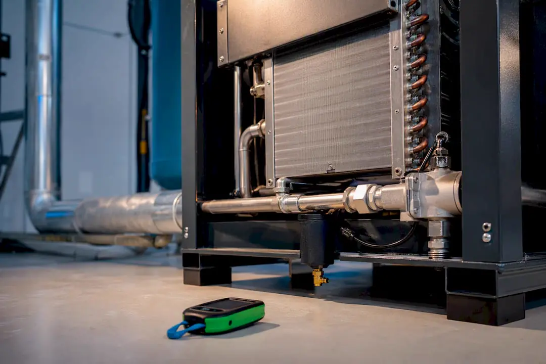
Operating costs of a compressed air dryer are mostly made up of electricity, with the remainder consisting of maintenance, spare parts, and equipment depreciation. The biggest drain on money comes from unnecessarily high operating pressure, insufficiently cooled inlet air, and a stricter dew point than the application actually requires. The ISO 8573-1 standard should not be taken as a mere formality here, because it precisely determines how much money the reader pays for each degree of drier air.
In brief:
- Increasing the operating pressure above 7 bar leads to a significant increase in energy costs, with every increase of 0.07 bar raising consumption by approximately 0.5 percent.
- Energy costs are the largest item in the budget, and for adsorption dryers, there is also the energy required for regenerating the drying medium, which is reflected in higher consumption.
- Servicing, replacement of the drying medium, and condensate drainage make up a significant part of the costs, while neglecting maintenance increases the risk of costly failures and corrosion.
- The operating temperature of the air and the correct choice of dryer type according to the required dew point significantly affect energy consumption and overall costs.
- Tips for savings include reducing operating pressure, monitoring compressed air leaks, and centralizing equipment, which can bring savings as early as the first year of operation.
Contents
- Operating costs of a dryer: what they consist of
- How pressure and temperature affect operating costs
- How much does dryer operation cost: calculation and example
- Dryer maintenance: costs and service intervals
- How to reduce dryer costs: quick measures with payback
- How Kompresory-vzduchotechnika approaches cost estimation
- Complete air treatment solution in one place
- Useful resources on this topic
- Frequently asked questions
Dryer operating costs: what they consist of
Energy is always the heaviest item in the budget for a compressed air dryer. For a refrigeration dryer, this means the power input of the compressor refrigeration circuit and the fan; for an adsorption dryer, it also includes the energy consumed during regeneration of the drying medium, whether this takes place through heating or through the loss of part of the compressed air to the regeneration cycle. The difference between the two types is crucial for the overall budget and we will discuss it in more detail in the section on consumption calculation.
The second largest category is service and consumables. This includes replacement of the drying medium (silica gel or molecular sieve in adsorption units), filter cartridges, valve seals, and regular refrigerant checks for refrigeration dryers.
The third item concerns costs associated with failure and condensate drainage. A malfunctioning or undersized dryer allows moisture to penetrate the distribution system, causing pipe corrosion, damage to pneumatic components, and contamination of production. Condensate drainage requires functional condensate separators and their regular inspection, otherwise the costs are simply shifted elsewhere in the system.
The last component is amortization. A dryer typically has a service life of 10 to 15 years, provided it receives adequate maintenance. The budget therefore also reflects the purchase price spread over the years of operation, not just routine servicing.
Summary of main items:
- Energy – power input of the dryer compressor, and for adsorption units, also medium regeneration
- Service and spare parts – filters, desiccant, seals, dew point sensors
- Condensate drainage – functional separators and their inspection
- Failure costs – corrosion of piping, production downtime, repairs of downstream components
- Depreciation – acquisition cost spread over the planned service life
How pressure and temperature affect operating costs
Operating pressure and inlet air temperature are among the parameters that have the greatest influence on how much a dryer actually consumes. Increasing pressure above 7 bar raises the compressor's energy consumption by approximately half a percent for each small increment above this value. In practice, this correction factor is calculated cumulatively, so a system running at 8.5 bar instead of the required 7 bar pays measurably more, without production gaining any benefit.
A higher inlet air temperature has a similar effect through a different mechanism. An underestimated ambient or inlet temperature reduces the dryer's capacity and increases the risk of condensation in the piping, so the dryer has to work harder to maintain the required dew point.
The choice between a refrigeration dryer and an adsorption dryer depends precisely on the required dew point according to ISO 8573-1. Refrigeration dryers typically achieve a dew point of around +3 °C and are more energy-efficient for common applications. Adsorption dryers can reach a dew point well below freezing, which requires more energy but is necessary for paint shops, pharmaceutical production, or the food industry.
Professional tip: Before purchasing a new dryer, have the actual inlet air temperature measured during summer operation, not just the catalog value for the compressor room – a difference of a few degrees can undersize even a correctly selected model.
How much does it cost to run a dryer: calculation and example
The annual energy cost of a dryer can be estimated using a simple formula: power input in kilowatts multiplied by the number of operating hours per year and the price of electricity per kilowatt-hour, adjusted by correction factors for pressure and temperature.
- Determine the dryer's power input – for a refrigeration unit, this is the nameplate power input of the compressor and fan; for an adsorption unit, it's the power input plus the energy of the regeneration cycle.
- Multiply by operating hours – typical three-shift operation means 6,000 to 8,000 hours per year.
- Add the price of electricity – at a price of around 4 to 5 CZK/kWh for industrial consumers, the annual energy cost of a medium-sized refrigeration dryer (5 kW) in three-shift operation comes to approximately 120,000 to 160,000 CZK for electricity alone.
- Adjust by the pressure correction factor – operating 0.5 bar above the necessary level increases this amount by a few percent, and for larger systems this means tens of thousands of CZK extra per year.
An adsorption dryer with the same flow rate typically consumes more energy due to regeneration, but heat recovery in drying systems can significantly narrow this gap, as it uses waste heat from the compressor station to heat the regeneration air.
Key figure: a small deviation in operating pressure, say 0.5 bar above the required value, translates through correction factors into a permanent increase in compressor consumption of a few percent, which accumulates over the entire operating life of the dryer.
The result is particularly sensitive to inlet temperature and pressure – two parameters that an operating technician can influence without investing in new equipment.
Dryer maintenance: costs and service intervals
The service interval for a dryer varies by type, but ignoring recommended intervals is one of the most costly mistakes in compressed air operation. Refrigeration dryers require inspection of the cooling circuit and cleaning of the condenser once or twice a year, while adsorption units need more frequent checks of valves and dew point sensors, since their cyclic chamber switching puts much greater strain on mechanical components.
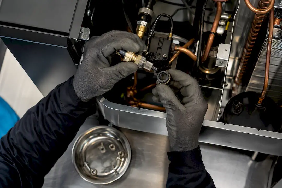
Replacement of the desiccant medium in adsorption dryers is handled once every 3 to 5 years, depending on the quality of the inlet air and the quality of filtration upstream of the dryer. Neglected filtration shortens the medium's service life and forces earlier, more costly replacement.
Warning signs that precede a costly failure include:
- Increasing noise or vibration of the dryer's compressor unit
- Slower achievement of the required dew point
- Frequent cycling of valves on the adsorption unit outside the normal rhythm
- Visible corrosion or moisture behind the condensate separator
It pays to calculate the total cost of ownership over the entire service life, not just the first years of operation, because neglected maintenance in the early years will come back as significantly higher repair costs later.
How to reduce dryer costs: quick measures with a payback
Reducing dryer operating costs doesn't have to wait for a new investment. Several steps will pay off already within the first year of operation.
- Reduce the operating pressure to the level actually necessary – even a drop of 0.3 to 0.5 bar will show up as a measurable energy saving for both the compressor and the dryer.
- Consider heat recovery for adsorption dryers – waste heat from the compressor room reduces the energy needed for media regeneration and shortens the payback period on the investment in a heat exchanger.
- Implement monitoring and rapid leak detection – inefficient compressed air systems lose up to 25% of energy through leaks, and this also applies to dried air, for which the operation paid extra.
- Centralize drying sources – aggregating several smaller dryers into one more efficient system reduces both the energy and service burden.
Professional tip: Schedule dew point and pressure measurements before and after any intervention in the system – without numbers, the savings can only be estimated, but with measurement they can be proven and justified to company management.
How Kompresory-vzduchotechnika approaches cost estimation
Technical consulting and energy audits focused specifically on dryer operation in the context of the entire compressed air system, not in isolation, are available. For an accurate estimate, we need basic operating data from the client: required flow rate, operating pressure, inlet air temperature, and operating regime (one, two, or three shifts).
Based on this data, a suitable dryer type can be recommended along with a realistic estimate of annual operating costs. For those interested in a more detailed analysis, we recommend a consultation or energy audit with a specific savings proposal tailored to the given operation.

A complete air treatment solution in one place
Direct access is available to technologies that actually affect dryer operating costs, without the need to assemble a solution from multiple suppliers. The range includes compressed air treatment units up to 18 bar, which combine filtration and drying into one compact unit.
For operations with strict air purity requirements, a compressed air filtration program according to ISO 8573 is available, which helps select the correct purity class without unnecessary overinvestment in a lower dew point than the application actually needs. In addition to equipment sales, turnkey solution design, installation, and energy audits are available, which reveal the actual reserves in a specific compressor room. For an individual calculation of operating costs and recommendation of a suitable dryer, you can use the contact listed on the specialists' pages through the range of pneumatic solutions and describe your operating regime.
Useful resources on the topic
- The importance of air drying in industry and construction
- 7-day audit for companies: reduce compressor operating costs
- Basic requirements for a compressor room: 2026 guide
Frequently asked questions
What has the biggest impact on a dryer's operating costs?
The biggest factor is energy consumption, which is increased unnecessarily by high operating pressure and high inlet air temperature. The second most significant item is regular servicing and replacement of the desiccant.
How often is the desiccant replaced in an adsorption dryer?
The desiccant in adsorption dryers is typically replaced once every 3 to 5 years, depending on the quality of inlet filtration and the load on the system.
Is a refrigerant dryer cheaper to operate than an adsorption dryer?
For common dew points around +3 °C, a refrigerant dryer is more energy-efficient. An adsorption dryer is necessary where the application requires a significantly lower dew point according to ISO 8573-1.
How much will reducing the operating pressure save?
Every 0.07 bar above the required 7 bar increases the compressor's energy consumption by approximately 0.5%, so even a small reduction in pressure will result in a measurable annual saving.
Who can help calculate the operating costs of a specific dryer?
Technical consulting and energy audits are available, which determine a realistic estimate of operating costs based on actual flow, pressure, and temperature.
Recommended

5 steps to calculate and verify air consumption in operation

Calculating air consumption means summing the flow rates of all connected devices weighted by their actual duty cycle, converting the result to a common reference state ANR or FAD, adding leaks and adding an operating margin. The resulting value is given in litres per minute or cubic metres per hour. It is recommended to verify it with a short-term flow measurement directly in operation, as manufacturers' catalogue data tends to be optimistic.
In brief:
- When calculating air consumption, it is necessary to convert the measured volumes to a uniform reference state and take into account leaks and an operating margin.
- The resulting flow rate is given in litres per minute or cubic metres per hour and should be verified by measurement directly in operation.
- To estimate the consumption of individual devices, a formula based on the number of strokes, volume per stroke and pressure is used, taking the duty factor into account.
- The total consumption is calculated as the sum of the flow rates of all devices with their duty cycles, to which leaks in the piping are added, which should be measured while the system is shut down.
- Continuous measurement and real-time monitoring help to more accurately detect leaks and adapt the sizing of the compressor station to actual operating conditions.
Contents
- Basic formulas and units for calculating air consumption
- Calculating air consumption for a pneumatic cylinder
- How to sum the consumption of all devices and account for leaks
- Measurement in practice: flow meters, sensors and continuous monitoring
- How to size a compressor based on the calculated consumption
- Step by step: from calculation to verification through measurement
- Experience with monitoring air consumption in practice
- How Kompresory-vzduchotechnika can help you with the calculation and sizing
- Frequently Asked Questions
Basic formulas and units for calculating air consumption
Before you start adding up the consumers, you need to master two things: converting volume to flow rate and understanding reference conditions. Without them, figures from different sources cannot be compared.
The volume a consumer uses per cycle is calculated as the piston (or diaphragm) area multiplied by the stroke. For a piston cylinder with a piston diameter of 40 mm and a stroke of 100 mm, the area is approximately 12.57 cm², so the volume per stroke is 125.7 cm³.
This volume is then converted to l/min by multiplying it by the number of cycles per minute. Ten cycles per minute at a volume of 125.7 cm³ gives approximately 1.26 l/min at operating pressure, but without correction for pressure.
This is where normalization comes into play:
- ANR (Atmosphère Normale de Référence) is a reference state according to the French standard, commonly used by European compressor manufacturers.
- FAD (Free Air Delivery) expresses the flow rate converted to the ambient air conditions at intake, i.e. the actual compressor output "drawn from the air".
- Both standards address the same problem: gas volume changes significantly with pressure and temperature, so without conversion to a common basis, consumption measured at 6 bar cannot be compared with consumption at 8 bar.
- The methodology for measurement and testing of compressors according to ISO 1217 defines how FAD is correctly determined under both laboratory and operational conditions, and it is the reference standard to which the rated values of most industrial compressors relate.
Calculating air consumption for a pneumatic cylinder
For an individual pneumatic cylinder, there is a simple formula established in technical practice:
Q = Z · (qp + qz) · n · 0.1
- Z is the number of cylinder strokes per minute (cycle frequency).
- qp is the volume of air required for the working stroke (in liters), qz is the volume for the return stroke.
- n represents the absolute pressure in bar (gauge pressure plus atmospheric pressure).
- The constant 0.1 converts the result into practical units of l/min.
Model example: a cylinder with a working stroke of qp = 0.05 l and a return stroke of qz = 0.04 l, a frequency of Z = 20 cycles/min, at a pressure of n = 7 bar absolute. Calculation: Q = 20 · (0.05 + 0.04) · 7 · 0.1 = 1.26 l/min. For hourly operation, this gives approximately 0.0756 m³/h.
There is a fundamental difference between single-acting cylinders, which consume air on only one stroke, and double-acting cylinders, where both directions of movement are counted. A double-acting cylinder therefore practically always has higher consumption at the same cycle frequency.
How to sum up the consumption of all devices and account for leaks
A single cylinder is easy to calculate. The problem arises when dozens of devices run simultaneously in a facility, each with a different duty cycle.
The basic formula for total consumption is as follows: Σ(qi · di) + Q_leak, where qi is the nominal flow rate of an individual device and di is the duty cycle factor expressed as the proportion of time the device actually draws air.
- A device running continuously has di = 1.0, while a pneumatic tool used only a few minutes per hour may have di around 0.1 to 0.2.
- For devices that never run simultaneously at full output, use a weighted average based on the actual operating cycle.
- For devices that may be switched on at the same time (typically several stations on one line), calculate the sum of their maximum consumption at the moment of overlap.
- Leakage (Q_leak) is included in the calculation as a separate item, because leaks in the distribution system consume air continuously, regardless of whether production is running.
Estimating leaks "on paper" tends to be inaccurate. A practice-proven approach is to measure consumption while production is shut down, when the only draw is from leaks.
Professional tip: If you don't have measuring equipment available, let the compressor run over the weekend, when production is shut down, and observe how often it cycles on. Every start means that air you've paid for is being lost through a leak into the system.
Measurement in practice: flow meters, sensors, and continuous monitoring
A calculation on paper is a starting point, not the final value. The actual consumption profile varies by shift, season, and the condition of the distribution system, which is why industrial practice combines calculation with measurement.
There are essentially three levels of technology available:
- Classic flow meters installed on the main branch or on individual sections of the distribution system, which provide an instant overview of consumption.
- Intelligent sensors with IO‑Link communication, for example the MP‑F series, which simultaneously measure flow, pressure, temperature and humidity and transmit data to the control system in real time.
- Cloud platforms for data collection, which generate graphs, reports and alarms from measured values when limits are exceeded, so you detect anomalies before they show up on your energy bill.
For a reliable consumption profile, it is recommended to measure at least one week of operation in order to capture all operating modes, including weekends and shift peaks. A shorter measurement can easily underestimate or overestimate actual consumption.
Continuous monitoring also allows early detection of a developing leak before it grows to tens of percent of total consumption, and gives the operations engineer utilization statistics from which to plan a potential expansion of the compressor station.

How to size a compressor according to calculated consumption
The calculated and measured consumption value is an input, not the final figure for selecting a compressor. Between the calculation and the purchase, there is still a decision regarding reserve and control.
- The target compressor flow is determined as the average consumption increased by a reserve for peak demand and possible future production growth, usually tens of percent above the average.
- The size of the air tank (reservoir) dampens short consumption peaks and reduces the number of compressor switching cycles, which extends its service life.
- For operations with variable demand, it is worth considering speed control or a combination of a smaller and a larger compressor, so the machine does not run unnecessarily at full power during low demand.
An overview of the compressor product range helps compare performance classes according to the calculated flow and choose the reserve level appropriate for your operation.
Step by step: from calculation to verification by measurement
It makes sense to divide the entire procedure into five steps that follow one another and can be repeated in any operation.
- Data collection – list the technical data sheets of all consumers, their rated flow rate and the actual number of cycles per shift.
- Calculation of Σ(qi · di) – for each consumer, determine the duty factor and multiply it by the rated flow rate.
- Adding leaks and a safety margin – add the estimated or measured leakage to the total and increase the value by a safety margin.
- Deploying measurement – install a flow meter or sensor and compare the measured profile with the calculation over at least one week of operation.
- Adjusting the sizing – based on the difference between the calculation and the measurement, adjust the compressor size, or alternatively identify leaks for repair.
Professional tip: Start with a rough estimate based on rated values, but never end the sizing there. A short measurement on the key branches of the distribution system will reveal differences that catalog figures will never capture.
Experience with monitoring air consumption in practice
From the dozens of operational audits we encounter at Kompresory-vzduchotechnika, one recurring issue stands out: companies calculate consumption based on nameplate values and then wonder why the compressor runs three times longer than it should. Diagnosing and eliminating leaks can bring significant energy savings, as can implementing continuous consumption measurement thanks to better control of the compressor station. I recommend a professional audit wherever the operation lacks its own measuring equipment, or where the results of DIY measurement differ substantially from the calculation.
— Zdeněk
How Kompresory-vzduchotechnika can help you with calculation and sizing
A calculation on paper is a good first step, but only a combination of measurement and professional assessment of the distribution system's condition provides real certainty. We offer a combination of measurement, component supply and service all in one place, so the customer doesn't have to deal with these services from multiple suppliers.
We provide consumption measurement directly on site, the design of a suitable compressor size based on the measured data, the supply of compressed air treatment units up to 18 bar and filtration according to the compressed air filtration program per ISO 8573, as well as installation and subsequent service. If your current calculations do not match the actual consumption, or if you suspect significant leaks, contact us with an inquiry for measurement or an energy audit. We will be happy to design a solution tailored to your specific operating profile.
Frequently Asked Questions
How to calculate air consumption for an entire facility?
Sum the nominal flow rates of all consumers weighted by their duty factor, add the measured leakage and a safety margin, then convert the result to a common reference condition ANR or FAD.
How to calculate air consumption from the compressor's power input?
Motor power input does not directly determine air flow, as it depends on efficiency and pressure. The actual flow (FAD) can be found on the compressor's nameplate or verified by measurement with a flow meter under the given operating conditions.
How to determine air consumption if I don't have technical data sheets?
The fastest way is short-term measurement using a portable flow meter or an IO‑Link sensor directly on the main branch of the distribution system, ideally for a period of at least one week of operation.
What is the difference between ANR and FAD when calculating air consumption?
ANR is a reference condition defining standard pressure, temperature, and humidity conditions, while FAD expresses the actual compressor output converted to these intake conditions. Without this conversion, flow rates measured at different pressures cannot be compared.
Recommended

Don't skimp on the backbone: designing a plastic compressed air distribution system for technicians

A plastic distribution system based on PA12 and push-fit fittings is suitable for workshops and light to medium-duty industry up to the working pressure typical for these systems. The conditions are correct sizing of diameters according to air consumption, quality filtration and drying, and installation according to the manufacturer's instructions. For heavier operations with high demands on mechanical resistance, an aluminium system remains the better choice. If you are not sure what type of distribution system your operations need, the technical support of Kompresory-vzduchotechnika will verify the design before purchase.
In short:
- Plastic PA12 distribution systems with push-fit joints can handle working pressure up to 16 bar, but are less resistant to mechanical damage and aggressive environments.
- Aluminium systems are more suitable for demanding operations with higher requirements on mechanical resistance and long-term stability of parameters.
- When sizing the distribution system, it is key to calculate the actual air consumption and add a reserve for future expansion instead of precisely planning the diameter.
- Installation of plastic pipes requires precision, correct deburring, insertion into the fitting, and secure fastening, while a pressure test reveals any leaks.
- A combination of an aluminium backbone with plastic branches is the most effective solution for balancing performance, durability, and costs in workshops and medium-sized operations.
Contents
- Plastic or aluminium: how to choose the material for air distribution
- Components and fittings: what a complete plastic distribution system includes
- How to size a plastic distribution system: procedure and calculation examples
- How the installation of a plastic distribution system proceeds step by step
- Connection to the compressor: air filtration and drying
- Maintenance of the air distribution system: what to check and how to fix faults
- Expert recommendation from Kompresory-vzduchotechnika for distribution system design
- Why conventional advice on sizing often fails
- Design and installation of the distribution system with Kompresory-vzduchotechnika
- Frequently asked questions
Plastic or aluminium: how to choose the material for the air distribution system
The choice between a plastic and an aluminium compressed air distribution system is not governed by price, but by operating conditions: pressure, temperature, mechanical load, and the environment through which the piping will run.
Plastic pipes made of PA12 can handle working pressures within the usual range used for these products and working temperatures within the range specified by manufacturers in technical datasheets, typically from light frost up to +60 °C. They are lightweight, do not corrode, and are installed without soldering or thread cutting. The push-fit system works on the principle of a plug-in connection with an O-ring; the pipe is simply pushed into the fitting and the joint is ready within seconds. It is precisely this speed of installation without special tools that reduces labour costs and the time needed for installation, which is especially noticeable in larger distribution systems with dozens of branches.
However, the limitations of plastic become apparent elsewhere. Push-fit joints have lower mechanical resistance to impacts and vibrations than welded or pressed aluminium joints, and in more aggressive chemical environments (solvents, certain oils) the pipe material or seals may degrade. For this reason, plastic is not suitable for facilities with intensive machine traffic, where mechanical damage to the piping is a risk, nor for environments with a high concentration of aggressive vapours.
Aluminium systems, such as the modular AIRnet solution designed according to the EN 13480-3 standard, can handle working pressure corresponding to common standards for this type of system, and thanks to their smooth internal surface, they have low pressure losses even over long runs. They are necessary where the distribution system must handle higher flow rates, where mechanical damage is a risk, or where operation requires long-term stable parameters without the risk of the plastic ageing.
In practice, a combination of both materials often proves effective. The backbone line, i.e. the main run from the compressor to the distribution points, is handled in aluminium for maximum durability and low pressure losses. The individual branches to the work stations are then completed with a plastic air distribution system, which is faster and cheaper to install.
Decision criteria for material selection:
- Working pressure and its stability – is the operation approaching the 16 bar limit, or is there a reserve?
- Mechanical risk – is a forklift operating in the area, can tools fall onto the piping, is there a risk of impact?
- Chemical environment – are there solvents, oils, or aggressive vapors in the air?
- Length and scope of the distribution system – is it a small workshop, or a large hall with dozens of outlet points?
- Budget and installation time – is there time available for a more complex installation, or is the priority a quick commissioning?
The combination of an aluminum backbone plus plastic branches is in practice the most efficient compromise between performance and cost, because it concentrates the investment in durability where it is actually needed, and saves money in places with lower risk.
Components and couplings: what a complete plastic distribution system includes
A complete plastic compressed air distribution system consists of more than just pipes. It functions as a system of several types of components, which must match each other in terms of pressure and material.
- PA12 pipes – form the backbone as well as the branches of the distribution system. Typical diameters for smaller workshops range from 15 to 28 millimeters for branch lines and around 32 millimeters for the main line. In larger facilities with higher consumption, pipes of 32 to 63 millimeters are used.
- Push-fit fittings – elbows, T-pieces, reducers, and couplings that allow assembly without tools. Quality fittings have integrated O-rings resistant to the oil contained in the compressed air system.
- Distribution boxes – local collection points from which air is distributed to individual workstations. They increase workplace flexibility, as they allow additional expansion with another outlet point without intervening in the main line.
- Shutoff valves and quick couplings – ball valves for isolating individual branches during servicing, and quick couplings for connecting pneumatic tools or hoses.
- Condensate separators and condensate drains – located at the lowest points of the distribution system, where moisture condenses, and at the inlets to distribution boxes.
- Pressure gauges – mounted at key points of the distribution system, usually at the outlet from the compressor station and at more distant end points, to allow monitoring of pressure drop.
- Mounting accessories – clamps, brackets and fasteners for securing the piping to the wall or ceiling according to the manufacturer's recommended spacing.
At critical points, such as transitions to the compressor, main shutoff valves or pneumatic tool connections, brass or steel fittings are often chosen instead of plastic ones. These materials better withstand repeated screwing, vibration from the compressor and mechanical stress when connecting hoses. The combination of "plastic on the run, metal at the contact points" is a common approach that extends the service life of the entire compressed air distribution system in the workshop without unnecessary extra cost.
How to size a plastic distribution system: procedure and calculation examples
Sizing a compressed air distribution system follows simple logic: first you determine how much air the system actually needs, then you select a diameter that will carry this consumption with an acceptable pressure drop, and finally you verify the design at the most distant end point.

Step 1: Determining the total flow rate. You add up the consumption of all pneumatic tools and machines that may be operating simultaneously, not the theoretical consumption of all equipment at once. In a workshop with multiple guns, it is common to assume that not all of them run continuously, so a simultaneity factor is used (usually 0.5 to 0.7 depending on the type of operation).
Step 2: Selecting the main line diameter. According to manufacturers' catalogue tables, for a given combination of flow rate and line length, the minimum diameter is selected that ensures a pressure drop within the recommended limit.
Step 3: Calculating pressure losses. Pressure loss increases with pipe length, the number of bends and fittings, and decreases with a larger diameter. A practical rule for workshop and smaller industrial distribution systems is to keep the total loss on the main line below 0.3 bar between the compressor station and the most distant take-off point.
Step 4: Verification at the end point. The most distant or highest-positioned workstation is the most critical point of the entire system. If the pressure drops there below the value required for correct tool operation, the entire design must be recalculated with a larger diameter or a shorter run.
Example calculation: a small workshop with three guns
The workshop uses three pneumatic blow guns, each with a consumption of around 250 litres per minute at peak load. With a simultaneity factor of 0.6, the actual peak consumption comes to approximately 450 litres per minute. For this consumption and a run of up to 20 metres, a 32 mm diameter backbone pipe with 15 to 20 mm branches to individual stations is usually sufficient.
Sample calculation: small production workstation with five outlets
An operation with five outlet points (a combination of blow guns and smaller pneumatic tools) and a total peak consumption of around 900 litres per minute over a run exceeding 40 metres already requires a 40 to 50 mm backbone to keep pressure loss within an acceptable range. Here it is worth considering an aluminium backbone with plastic branches.
Practical recommendations for forward-looking design:
- Design the backbone diameter with a reserve of one to two sizes above the current requirement, rather than sizing it exactly to the current consumption.
- Position distribution boxes so that they allow additional outlets to be connected without intervening in the main line.
- Keep in mind that every future branch will increase the pressure loss on the backbone, so a reserve in diameter pays off financially as well, since it avoids a complete rebuild of the distribution system.
- For operations anticipating production expansion, it is better to invest in a backbone one size stronger right at the first installation.
A detailed procedure with specific pressure loss tables and recommended diameters for various scenarios can be found in a separate guide to sizing compressed air distribution systems.
How the installation of plastic piping proceeds step by step
Installing compressed air with plastic piping is faster than with welded systems, but the precision of individual steps determines how long the distribution system will last without leaks.
- Route preparation. Check the strength of the walls or ceiling for mounting, calculate the minimum bend radii according to the pipe manufacturer's specification, and plan the spacing of brackets, usually every 50 to 100 centimetres depending on the diameter.
- Cutting and deburring. Cut the pipe at a right angle using special pliers or a saw designed for plastic, then remove burrs from both the inner and outer edges. Burrs are the most common cause of O-ring damage when inserting into the fitting.
- Cleaning the pipe end. Before inserting into the fitting, wipe the pipe end with a dry cloth to prevent shavings or dust from entering the joint.
- Insertion into the push-in fitting. Insert the pipe with even pressure all the way to the stop, not at an angle. Most push-fit systems have a visual mark on the pipe or fitting that confirms the correct insertion depth.
- Joint inspection. After insertion, try gently pulling the pipe back. A properly made joint will lock and not loosen. If a joint is questionable, disassemble it and redo it.
- Pipe fixing. Secure the line using clamps and brackets at the recommended spacing so that the piping does not transfer its own weight onto the joints.
- Pressure test. Before commissioning, the distribution system is tested at a pressure of 1.5 times the rated working pressure for 30 to 60 minutes. Monitor the pressure drop on the pressure gauge and check all joints using a foam test solution.
Professional tip: A leak in a push-fit joint is most often detected by a hissing sound when the compressor is switched off and the workshop is quiet. If the pressure keeps dropping during the test even after a visual check of all joints, focus on the points where the pipe changes direction — insertion is most often imperfect there.
The most common installation error is insufficient insertion of the pipe into the fitting, whether due to burrs or failure to align with the depth mark. The second typical error is overtensioning the pipe between brackets, which leads to mechanical stress on the joints during temperature changes. A detailed installation checklist can be found in the guide to setting up a compressed air distribution system step by step.

Connecting to the compressor: air filtration and drying
A plastic compressed air distribution system is more sensitive to the quality of the air passing through it than an aluminum system, because moisture and contaminants damage the seals in push-in fittings more quickly. Filtration and drying are therefore not an add-on, but a condition for long service life.

Quality air treatment prevents the accumulation of condensate and mechanical contaminants, which otherwise shorten the service life of plastic pipes and joints. Moist air also promotes corrosion of metal fittings in the system and increases the risk of condensate freezing during winter months in unheated workshops.
For workshop operation, a combination of a cyclone separator and a membrane or adsorption dryer with an achieved dew point of around +3 to +5 °C is usually sufficient. Industrial operations with higher demands on air dryness, such as paint shops or food industry lines, choose adsorption dryers with a lower dew point and multi-stage filtration.
Recommended placement of air treatment components in the distribution system:
- Main filter and dryer right after the compressor's air receiver, before the split into the backbone line.
- Secondary filters at distribution boxes leading to sensitive applications (spray guns, measuring instruments).
- Condensate drains at every lowest point of the line and at the entry to vertical branches.
- Pressure safety margin between the maximum working pressure of the plastic piping (up to 16 bar) and the set pressure of the compressor; a margin of at least 1 to 2 bar is recommended.
The basic principles of how the whole system works, including the role of the compressor and air treatment, are described in the article on how pneumatics works in industry.
Maintenance of the air distribution system: what to check and how to fix faults
Regular inspection of the compressed air distribution system reveals minor leaks before they manifest as a loss of compressor performance or unnecessary energy costs.
Monthly, it is advisable to check noisier joints by listening and to visually inspect the visible piping routes. Annually, a more thorough inspection is recommended, including a pressure test of the entire system and a check of the condition of the filters and dryer.
- Leak diagnostics – an ultrasonic leak detector or a simple foam spray will reveal even small leaks that are inaudible during normal listening checks.
- Pressure drop measurement – a portable pressure gauge placed at the beginning and end of the line will show whether the losses are increasing compared to the designed values.
- Most common faults – a loose push-fit connection (solution: disassemble, check the O-ring, reinsert), an O-ring damaged by aging (replace with an original part), a clogged condensate drain (cleaning or replacement).
- When to call service – in case of repeated leaks at the same spot, pressure drop even after checking the connections, or during a planned inspection of the entire compressed air system including the compressor station.
A service intervention should include not only repairing the specific fault, but also checking whether a systemic problem has occurred, such as a poorly dimensioned line or inadequate air treatment.
Expert recommendation from Kompresory-vzduchotechnika for distribution design
A typical inquiry that smaller workshops bring to Kompresory-vzduchotechnika concerns distribution for three to five work stations with a combination of blow guns and manual pneumatic tools. For production facilities, it is often about expanding an existing distribution system to add a new line or workstation.
Before consulting a technician, it makes sense to have basic data ready: the expected number of stations and their current air consumption, the required working pressure at the end tools, and an estimate of the line length from the compressor. With these details, the diameter design and material choice can be verified during a single consultation, instead of fixing mistakes after installation.
Zdeněk, who handles technical consulting on compressed air systems at Kompresory-vzduchotechnika, has long observed that the most common cause of dissatisfaction with a plastic distribution system is not the material itself, but an undersized backbone diameter already at the design stage.
Why conventional dimensioning advice often fails
Most guides to compressed air distribution focus on which material is "better," while underestimating that ninety percent of real-world problems arise from poor dimensioning, not the choice of plastic or aluminum. I have seen facilities where a plastic push-fit distribution system has worked without a single failure for ten years, because it was designed with a margin. And I have seen aluminum installations where investing in a more expensive material did not save an undersized backbone.
Conventional advice also often overlooks that filtration and drying are not a cosmetic add-on, but directly affect how long push-in connections last. Condensate in the piping ages O-rings faster than UV radiation or temperature fluctuations.
If I had to recommend a single priority to readers, it would be this: before deciding on the material, calculate the actual consumption with a simultaneity factor and add a margin for future expansion. The material is the second decision, not the first.
— Zdeněk
Design and installation of distribution systems with Kompresory-vzduchotechnika
Kompresory-vzduchotechnika handles compressed air distribution comprehensively, from diameter calculations through component supply to installation and service, so you don't have to rely on estimates or combine deliveries from multiple vendors. We offer a turnkey design including technical consultation, supply of both plastic and aluminum components, an installation team, and service support for any later modifications or inspections.
Proper air treatment is also part of every functional distribution system. Our range includes compressed air treatment units for removing impurities, as well as dryers for condensate removal, which extend the lifespan of the entire distribution system. For operations with higher working pressure, robust treatment units up to 18 bar are also available.
If you're not sure what pipe diameter and what type of air treatment your workshop or facility needs, ask the Kompresory-vzduchotechnika technical support team for a design proposal or price quote before ordering materials.
Frequently Asked Questions
Up to what pressure is a plastic compressed air distribution system safe?
Plastic systems made of PA12 material with push-in fittings can handle a working pressure of up to approximately 16 bar, though the exact value varies depending on the manufacturer and fitting type, so always check the technical data sheet of the specific product.
What pipe diameter should be chosen for a small workshop?
For smaller workshops with a few blow guns, pipes of 15 to 28 millimeters for branch lines and 32 millimeters for the main line are usually sufficient, but the exact diameter depends on the number of outlets and the length of the route.
How long does a plastic distribution system last compared to an aluminum one?
With proper installation, filtration, and air drying, a plastic distribution system will last for many years without issues, but aluminum systems generally withstand mechanical loads and harsher environments better, making them more durable in demanding industrial settings.
How is leak tightness tested after installation?
The distribution system is tested at 1.5 times the nominal working pressure for 30 to 60 minutes, during which the drop is monitored on the pressure gauge and the joints are checked using a foam test solution.
When is it better to combine plastic with aluminium?
The combination pays off where the main backbone line needs higher mechanical resistance and low pressure losses, while individual branches to workstations can be solved more quickly and cheaply with a plastic distribution system. Kompresory-vzduchotechnika recommends this modular approach as a common standard for medium-sized operations.
Recommended

Without frequent cycling: compressor pressure switch settings for the workshop
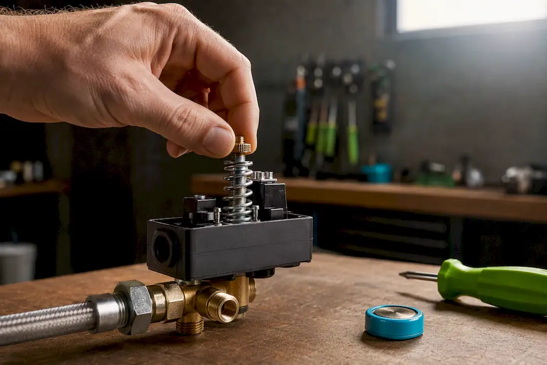
Turn off the power supply, release the pressure from the air tank, and connect a test pressure gauge. First set the cut-in (switching-on) pressure using the main nut, and only then set the differential (the difference between switching on and off) using the differential nut. The minimum hysteresis for mechanical switches is typically at the common physical limit, and a smaller difference cannot be set on most models. After adjustment, perform three to four test cycles and fine-tune if necessary.
In brief:
- The minimum possible differential setting is approximately 0.6 bar, and if more precise regulation is needed, it is necessary to switch to an electronic pressure regulator.
- After adjustment, three to four test cycles must be performed to verify the stability and correctness of the setting, and further fine-tuning must be carried out if necessary.
- The correct sequence is the most important part of the adjustment: first the cut-in pressure is set using the main nut, then the differential nut is adjusted, and the tests will show the actual difference between them.
- Faulty or worn contacts in the switch are a common cause of frequent cycling and can also be the cause even when the mechanical setting is correct.
- Regular inspection and maintenance of the switch, including checking the contacts and springs, extends its service life and reduces the risk of failures.
Contents
- What is a pressure switch and how does it work
- Tools, safety, and preparation before adjustment
- How to set the compressor pressure switch step by step
- Inspection after adjustment and the most common faults
- Maintenance of pressure switches and prevention of other problems
- Why you can rely on this guide
- Editorial perspective: the order of steps matters more than precision
- When adjustment is not enough, equipment and service can help
- Frequently asked questions
What a pressure switch is and how it works
The pressure switch sits between the air tank and the compressor head and determines when the motor runs and when it stops. Inside there is a diaphragm or piston, against which air from the tank pushes. Opposing it acts a spring, whose tension you set using an adjusting nut. When the pressure exceeds the set limit, the diaphragm switches the contacts and the motor turns off. As soon as the pressure drops by a certain difference, the contacts reconnect and the compressor starts up again.
This difference between the cut-out and cut-in pressure is called the differential or hysteresis. Without it, the switch would click practically continuously around a single value, which would destroy the contacts and the motor within a few weeks. That is precisely why the switch is adjusted in two steps, not with a single turn of a screwdriver.

Tools, safety and preparation before adjustment
Before touching the switch cover, disconnect the compressor from the mains and switch off the relevant circuit breaker. Drain the air tank through the drain valve, so that the components are not under pressure that you would be handling blindly. Only then does it make sense to open the cover and move the nuts.
For the adjustment itself you only need a few things:
- a calibrated reference pressure gauge, ideally on a separate branch, not just the one built into the switch,
- a box wrench or flat wrench for the adjustment nuts,
- a screwdriver to remove the cover,
- insulated tools, if you will be working under the cover near live contacts.
While fine-tuning the cycles, you will need to leave the system pressurized and the power on, otherwise you will not find out at what value the switch actually reacts. However, do this only with the cover in place or at least with your hands away from the contacts, and if you are not sure, it is better to leave the fine-tuning to a service technician.
Professional tip: Position the check pressure gauge so that you can see it even while turning the nut. You will save yourself from running back and forth and from incorrect readings caused by recording the value two seconds later than it actually occurred.
The guide to measuring air pressure describes in more detail how to choose and position a suitable instrument.
How to set the compressor pressure switch step by step
Setting the compressor pressure switch has a fixed sequence. If you reverse it, the switch easily gets "out of tune" and you start adjusting from zero. Proceed as follows:
- Remove the switch cover. Underneath it you will find two nuts or screws: the main one (often marked P or "Main"), which determines the cut-in pressure, and the differential one (ΔP or "Diff"), which determines the difference between cut-in and cut-out.
- First set the cut-in pressure using the main nut. Turning clockwise increases the pressure, turning counterclockwise decreases it. Watch the pressure gauge and release air from the tank until the motor starts again at the desired value as the pressure drops.
- Then adjust the differential using the differential nut. Here you determine by how much the pressure must rise above the cut-in value before the switch turns the motor off again. Here too, turning clockwise increases the difference.
- Verify both points by measurement. Let the tank fill up until it switches off, then release air and record at what value the motor starts. The difference between the cut-out and cut-in values is your actual differential.
- If the differential blocks further adjustment of the cut-in pressure, loosen the nut completely and start again from step 2. Trying to tighten both nuts at the same time only results in not knowing which value corresponds to what.
For a typical workshop application, the cut-in and cut-out pressure settings are usually set so that the differential matches the needs of the equipment. For more sensitive tools, where you want more stable pressure, the differential is kept close to the minimum that a mechanical switch can handle.
Minimum hysteresis: on most mechanical pressure switches, the differential cannot be reduced below approximately 0.6 bar. Attempting a smaller difference usually results in the switch not responding to the released air at all, because it is physically at the limit of its mechanism.
If you need a really narrow hysteresis, for example around 0.1 to 0.2 bar for sensitive pneumatic automation, a mechanical switch is not sufficient, and the solution is an electronic pressure regulator. However, this is a different category of device than the classic diaphragm switch described above.
The chosen target value for the cut-in pressure should be based on what you actually need for the job. The relationship between working pressure and tool performance is discussed in the article on the effect of pressure on tools, which will help you estimate whether 6 bar is enough, or whether you need more.

Check after setting and the most common faults
After completing the adjustment, let the compressor run through three to four complete cycles, i.e. filling the tank and releasing it down to the cut-in pressure. Watch the pressure gauge to see if the cut-in and cut-out values repeat stably, and not that they shift by a tenth of a bar with each cycle.
The most common symptoms of an incorrectly set or worn switch:
- Frequent cycling – the motor starts and stops at short intervals because the differential is set too narrow or the spring has lost its elasticity.
- Motor overheating – a consequence of the previous point; the motor does not have time to cool down between cycles, and its service life is significantly shortened.
- Current spikes on startup – repeated frequent starts put more strain on the electrical wiring and the circuit breaker than they are rated for.
- The switch does not respond at all – this is usually due to a stuck spring, corrosion on the contacts, or a mechanical fault inside the switch, not a setting error.
If the problem recurs even after readjusting the differential, check the electrical contacts under the cover. Frequent cycling is often just as commonly caused by worn contacts as by actual incorrect settings, and this is easily mistaken for a "poorly adjusted switch". The connections between cycling, the circuit breaker, and overheating are discussed in more detail in the articles on screw compressor overheating and on a compressor that trips the circuit breaker.
Maintenance of pressure switches and prevention of further problems
A pressure switch does not require complex care, but a few minutes of occasional inspection will save you from having to readjust it again later. Recommended schedule:
- Once every three to six months, check the cover and contacts for corrosion or dust buildup from the workshop.
- At each inspection, try using your hand or a wrench to verify that the adjustment nuts have not seized and that the spring moves freely.
- In humid or dusty environments, consider a shorter inspection interval, as a corrosive environment wears out the switch faster.
If the problem persists even after repeatedly readjusting the differential and the cut-in pressure, and the contacts appear to be in good condition, the switch is probably mechanically worn out and further adjustment will not help. At this point, it is cheaper and more reliable to replace it than to waste time in the workshop with a tool that only holds its setting for a few hours.
Professional tip: It is worth keeping a simple record of when you first adjusted the switch and what values you set. At the next inspection, you will immediately be able to tell whether the values have drifted on their own or whether the problem lies elsewhere. A practical overview of other errors in compressor operation can be found in the article on the most common mistakes when using compressors.
Why you can rely on this guide
The procedure is based on a principle followed by all mechanical switches regardless of manufacturer: first the cut-in pressure, then the differential, never the other way around. The text was written by Zdeněk, technical editor at Kompresory-vzduchotechnika, who has long been involved in the operation and service of compressor systems. If you encounter a non-standard setup or a recurring fault that adjustment does not resolve, consulting technical service will save more time than further blind attempts.
Editor's perspective: the order of steps matters more than precision
Most guides focus on exactly how to turn the nut a quarter turn. But that is a secondary detail. What matters is the order. I have seen descriptions recommending that the differential be set first because "it's a simpler number". It is a simpler number, but it unnecessarily complicates the whole procedure, because the differential is always calculated from the cut-in pressure, not the other way around.
The second thing people underestimate: hysteresis of around 0.6 bar is not a shortcoming of the specific switch you bought. It is a physical limit of the mechanism as such. If you need more precise regulation, the solution is not to look for a "better" mechanical switch, but to switch to electronic regulation. Third, test cycles after adjustment are not a formality at the end. They are the only way to reveal that a problem you attributed to the switch is actually being caused by worn contacts. Anyone who skips this step will keep readjusting over and over and never find out why.
— Zdeněk
When adjustment is not enough, equipment and service can help
If adjusting doesn't suit you or you want certainty of accurate measurement, Kompresory-vzduchotechnika offers calibrated pressure gauges, replacement pressure switches, and expert consultation, without having to book a full day of service for a single nut.
Suitable hoses and accessories to complete the measuring path can be found in the hoses and accessories category. For more complex faults where adjusting the differential doesn't solve the problem, it is faster to have the switch checked than to disassemble it repeatedly just to test it.
Frequently asked questions
How to adjust a pressure switch on a compressor?
Disconnect the compressor from the mains, release the pressure, connect a pressure gauge, and first set the cut-in pressure using the main nut, only then the differential using the differential nut. After adjustment, run several test cycles.
How to regulate the pressure on a compressor?
Operating pressure is controlled via the pressure switch, which switches the motor on and off according to the values set on the main and differential nuts. More precise regulation beyond what a mechanical switch offers is provided by an electronic pressure regulator.
What is the minimum difference between the cut-in and cut-out pressure?
For most mechanical switches, the minimum adjustable differential is around 0.6 bar. Below this threshold, a standard mechanical switch usually cannot be adjusted.
What to do when the differential is blocking further adjustment of the cut-in pressure?
Fully loosen the differential nut and start again from setting the cut-in pressure. Adjusting both nuts at the same time only leads to confusion about which value corresponds to what.
What causes the compressor to cycle frequently after adjustment?
Most often a too narrow differential or worn electrical contacts in the switch. If fine-tuning the differential does not solve the problem, the contacts need to be checked or the switch replaced.
Recommended


5 steps to selecting an industrial compressor for your company, with a 20–25% reserve
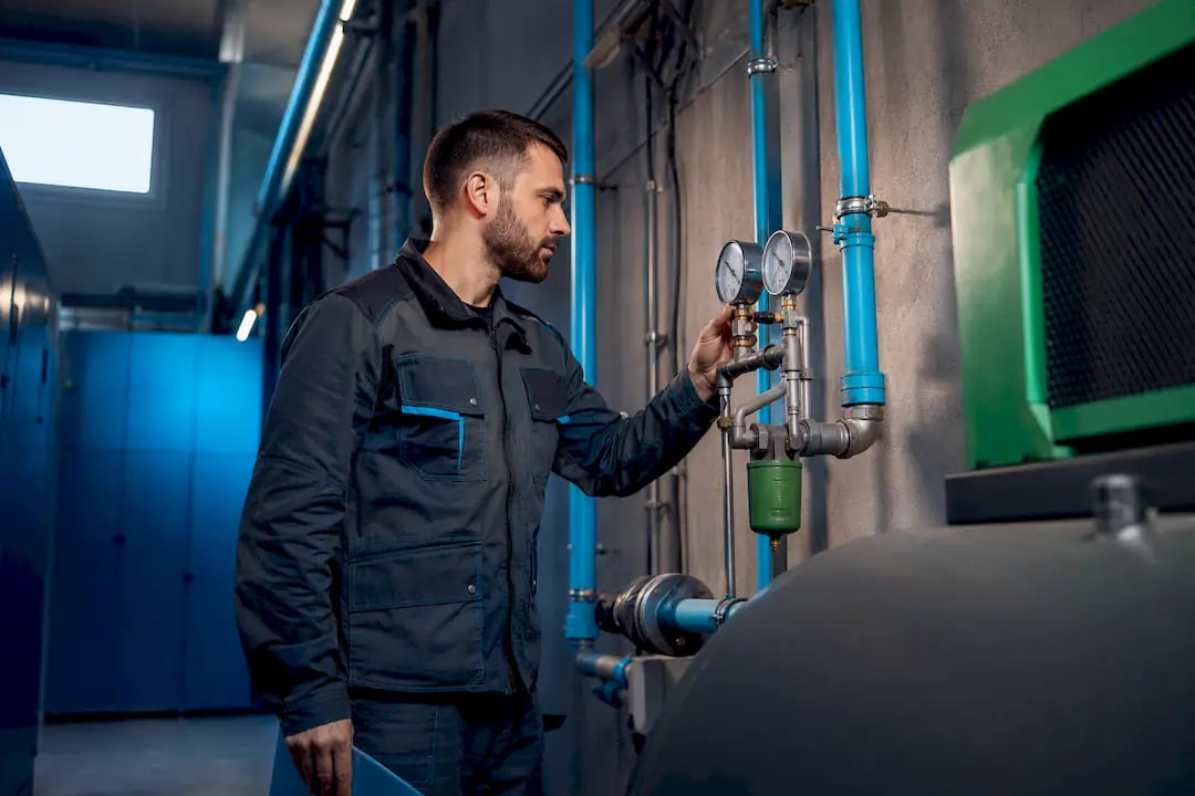
For stable continuous production, choose a rotary screw compressor; for intermittent operation, a piston compressor is sufficient. Four figures are decisive: the required flow rate in m³/min, the operating pressure in bar, the required air purity class according to ISO 8573, and the nature of the load throughout the day. Before requesting offers, determine the average and peak load and consider variable speed drive (VSD) where air demand fluctuates.
In brief:
- Piston compressors are suitable for intermittent operation, while rotary screw compressors are the best choice for continuous industrial use.
- A higher air purity class according to the ISO 8573 standard is required in the food industry, pharmaceuticals, and other sensitive sectors, where oil and moisture must be eliminated.
- Correct compressor sizing depends on actual consumption in m³/min, the required pressure, and a reserve of 20–25%, and it is recommended to compare this with the technical data at operating pressure.
- Variable speed drive (VSD) brings greater energy savings in fluctuating operations where air demand varies, while in steady operation, a fixed-speed option is more advantageous.
- When choosing a compressor, it is important to consider not only the purchase price but also the operating costs and regular servicing, which minimizes the risk of unplanned downtime.
Contents
- How to choose an industrial compressor: piston or screw?
- How to calculate the required compressor flow rate and pressure
- When is variable speed drive (VSD) worth it?
- What air quality is needed according to ISO 8573
- How much does compressor operation cost per year?
- What are the requirements for installation and noise level of a compressor
- Checklist: steps to selecting the right compressor
- What practice says: a view on compressor selection
- Choose a compressor with expert advice from Kompresory-Vzduchotechnika
- Recommended resources for further study
- Frequently asked questions
How to choose an industrial compressor: piston, or screw?
A piston compressor compresses air by the movement of a piston in a cylinder. It is a simpler, cheaper technology with a lower purchase price, but with higher wear during long operation. A screw compressor compresses air between two interlocking rotors and handles continuous operation considerably better. For continuous industrial operation, rotary screw units are therefore usually more suitable, while piston compressors prove themselves in intermittent operation and less demanding applications, where the machine runs only part of a shift.
The choice between an oil-lubricated and oil-free design depends on what you plan to do with the air:
- Oil-lubricated compressors are cheaper to operate and suitable where the air does not come into contact with the final product.
- Oil-free compressors are necessary in the food, pharmaceutical, or electronics industries, where traces of oil would devalue the product.
- Oil-free technology requires more frequent servicing of compressor heads, but it saves you additional filtration stages.
- Oil-lubricated solutions, on the other hand, need quality oil separation and regular filter replacement.
The choice of technology also affects installation: screw compressors require more carefully planned cooling and heat dissipation, while piston compressors are less demanding but louder during extended operation.
How to calculate the required compressor flow and pressure
Sizing is mathematics, not a rough estimate. According to manufacturers, it is essential to take into account both daily and peak air demands, since an oversized unit increases costs while an undersized one limits production. Proceed as follows:
- List the consumption of each tool in m³/min according to the nameplate, including the pressure at which the consumption applies (usually 6 or 7 bar).
- Determine the cycle time – what percentage of the shift the tool is actually in operation (duty factor).
- Add up the real consumption of all devices running simultaneously, not the theoretical maximum of all tools at once.
- Add a reserve of 20 to 25% for leaks in the piping, future expansion, and system aging.
- Compare the result with the pressure drop in the piping – the compressor must deliver the tool's pressure plus the losses in the piping and filtration.
Professional tip: Never size solely according to the rated motor power in kW – what matters is the actual delivered flow at your operating pressure, which you will find in the technical data sheet, not on the nameplate.
For critical operations, one main unit is often combined with a backup, so that servicing or a failure does not stop production.
When does speed regulation (VSD) pay off?
A compressor with VSD (variable speed drive) adapts the motor speed to the current air demand, instead of running at full power and releasing the surplus. Where air demand fluctuates – multi-shift operations, seasonal production, a variable number of active tools – it brings noticeable energy savings.
According to data from manufacturer Atlas Copco, speed regulation in operations with fluctuating consumption can bring substantial energy savings compared to a fixed-speed unit, depending on the specific load profile.
Practical recommendations:
- For operation with significant demand fluctuations, choose a combination of one VSD compressor and one fixed-speed unit – the VSD covers peaks and fluctuations, while the other holds the base load.
- For stable, fully loaded continuous operation, the investment in VSD pays off more slowly – there, a fixed-speed unit is sufficient.
- The decision should be based on actual consumption measurement, not on estimates.
What air quality is needed according to ISO 8573
The ISO 8573 standard defines compressed air purity classes based on the content of solid particles, moisture, and oil. Air quality is critical especially where the air comes into contact with the product or precision components, and some applications require oil-free air with additional filtration and drying.
- Lower ISO 8573 class (common pneumatic tools, workshop operation) – basic filtration and a refrigerant dryer are sufficient.
- Higher ISO 8573 class (painting, electronics, laboratories) – a combination of an oil-lubricated compressor with multi-stage filtration, or an oil-free solution, is necessary.
- Food and pharmaceutical industry – an oil-free compressor is practically required without exception, supplemented by a dryer and filtration according to hygiene requirements.
Dryers are divided into refrigerant dryers, suitable for common industrial use, and adsorption dryers, which achieve a much lower dew point for sensitive applications. In practice, it is common to supplement the system with a dryer, filters and an air tank, which stabilises the air supply even during peak demand. Specific compressed air treatment units up to 18 bar handle both filtration and drying in one compact unit.
How much does it cost to operate a compressor per year?
The purchase price is only a fraction of the total cost of ownership (TCO). The calculation should include the investment, energy consumption, servicing, spare parts and losses caused by downtime. Energy costs form a significant part of the TCO, and investments in efficiency, such as VSD or optimisation of distribution lines, often pay off in the form of lower operating expenses.
- Monitor the operating temperature, pressure fluctuations and oil condition – deviations signal an impending fault earlier than before the line is shut down.
- Follow the service intervals specified by the manufacturer; for screw compressors, this usually means changing the oil and filters after a set number of operating hours.
- A service contract with regular inspections minimises the risk of unplanned downtime far better than a reactive approach of "let's wait until something breaks".
Professional tip: Do you keep an operating log with temperatures and pressures? A deviation of a few degrees above the usual value is often the first sign that a service intervention is approaching – not yet a fault.
What are the installation and noise requirements for a compressor
Screw compressors without an acoustic enclosure commonly reach a noise level that complicates normal communication in a small workshop. The solution is an acoustic enclosure, sufficient distance from workstations, or a separate compressor room.
- A compressor room needs effective ventilation – heat dissipation is essential, because an overheated compressor loses performance and wears out faster.
- Keep free access to the service panels; filters and oil must be accessible without dismantling the surrounding structures.
- Placement on flexible mounts limits the transmission of vibrations into the building structure.
- Safety clearances and marking of pressure vessels must comply with applicable standards for pressure equipment.
You can find a detailed overview in the article about basic requirements for a compressor room.
Checklist: steps to selecting the right compressor
Before contacting suppliers, go through the five steps that form the backbone of any reasonable inquiry:
- List your consumption – record the power of all pneumatic tools and their actual utilization factor.
- Calculate the required flow rate and pressure including a reserve of 20 to 25%.
- Choose the technology – screw for continuous operation, piston for occasional use, oil-free where product cleanliness requires it.
- Verify air quality according to ISO 8573 and add filtration or a dryer as needed.
- Consider VSD, redundancy, and service support and prepare these figures as a basis for consultation with the supplier.
With this information, you will receive a tailored offer from the supplier, not a catalog-based estimate.
What practice says: a look at compressor selection
The recommendations in this article are based on common practice in industrial operations – car factories, foundries, and production lines, where an undersized compressor means lost production and an oversized one means unnecessary energy costs. The author of articles on Kompresory-Vzduchotechnika, Zdeněk, has long focused on the technical side of compressor selection and air treatment.
Kompresory-Vzduchotechnika helps companies turn these figures into a real solution – from measuring consumption through designing the assembly to installation and service. If you have data from the checklist above, a consultation with prepared figures will save time for both sides.
— Zdeněk
Choose a compressor with expert advice from Kompresory-Vzduchotechnika
Kompresory-Vzduchotechnika offers what a catalog alone cannot: a technician who will go through the measured figures with you and design an assembly tailored precisely to your operation, instead of selling you the first compressor based on motor power.
In the offer you will find piston and screw compressors in oil-lubricated and oil-free versions, complemented by filtration according to the ISO 8573 standard and dryers for the required air purity class. The consultation includes measuring the actual consumption, designing a suitable technology and capacity reserve, preparing an offer, and subsequently installation and service support. If you are also dealing with related pneumatic equipment, a range of pneumatic tools is also available. Get in touch with the figures measured from the checklist above and have a specific assembly design tailored to your operation prepared for you.
Recommended resources for further study
You can find deeper technical materials in the internal articles on factors for selecting a compressor, comparison of screw and piston compressors, and the checklist on buying a compressor for a workshop or company.
Frequently asked questions
Which compressor should I choose for my company?
For continuous industrial operation, choose a rotary screw compressor; for intermittent or occasional operation, a cheaper piston compressor is sufficient. The decisive factors are the actual consumption in m³/min, the required pressure, and the nature of the load.
What is the intake capacity of a compressor and how do I determine it?
Intake capacity indicates the amount of air a compressor delivers per minute at a given pressure, usually in m³/min. You determine it by adding up the consumption of all tools running simultaneously and adding a reserve of 20 to 25 %.
Which is better, an oil-lubricated or oil-free compressor?
An oil-lubricated compressor is cheaper to operate and suitable for common workshop and industrial use. An oil-free compressor is necessary where air comes into contact with the product, for example in the food or pharmaceutical industry.
What compressor is suitable for a home workshop or small operation?
For smaller intermittent operation, a smaller piston compressor with sufficient reserve relative to the rated consumption of the tools is sufficient. For more regular all-day use, it is worth considering even a smaller screw unit.
When is investing in VSD speed control worthwhile?
VSD pays off especially in operations with fluctuating air consumption, for example with multiple shifts or variable tool workload. In stable, fully loaded continuous operation, the payback is slower and fixed speed is sufficient.
Recommended

Select a mobile compressor based on flow rate and a 2 bar reserve
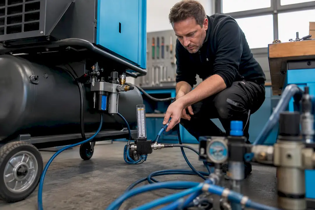
For home and workshop use, choose a portable piston compressor with effective flow matching common workshop tools and an air tank of suitable size. For inflating tyres and minor blowing, a model with lower flow is sufficient; for painting and more demanding tools, higher flow is needed. For field deployment and sandblasting, consider a diesel screw compressor. You can then fine-tune the specific model according to the checklist below.
In brief:
- A transportable piston compressor with a flow of 150–300 l/min and an air tank volume of around 24 litres is suitable for a home workshop or hobby use.
- For longer uninterrupted work or sandblasting, towable diesel compressors with a larger air tank capacity and high flow are more suitable.
- When choosing, you need to monitor the effective flow at the required pressure, a pressure reserve of at least 2 bar, and a corresponding transport system according to the surface and weight of the machine.
- Oil-free compressors are more suitable for painting or medical work, while oil-lubricated ones better handle long-term and demanding operation.
- With electric models, you need to account for limited output and dependence on the electrical grid, or for field deployment, choose a diesel or battery-powered solution.
Contents
- What types of mobile compressors exist
- What flow, pressure, power and air tank volume mean
- Which drive to choose for mobility in the field and in the workshop
- Oil-lubricated or oil-free compressor
- How noise level affects the choice for a workshop or home
- What each compressor type is suited for by task
- How to choose step by step and what to ask the seller
- Personal recommendations for choosing a mobile compressor
- Where to find a suitable mobile compressor and accessories
- Recommended resources for further reading
- Frequently asked questions
What types of mobile compressors exist
A mobile compressor is not a single category, but a group of machines with different designs and purposes. A portable piston compressor, with or without wheels, is the classic choice for a workshop or garage. A weight of 20 to 60 kg allows it to be moved by one person, and power supply is typically 230 V from a standard outlet.
A wheeled compressor on a chassis with larger wheels and a tow bar is intended for construction sites and service shops, where the machine is moved between locations daily, but not on public roads. The air tank volume is usually 50 litres or more.
Battery-powered compressors address work without access to electricity, usually only for inflating tyres or minor air top-ups. Output is limited, and they cannot withstand extended continuous operation.
Diesel (towable) compressors are towed behind a vehicle or have their own chassis with a brake. They are deployed in the field, on construction sites without an electrical connection, or for sandblasting, where a standard 230V motor is not sufficient.
- Portable piston: workshop, garage, hobby, tyre service
- Wheeled (230 V/380 V): construction site, car repair shop, longer shifts
- Battery-powered: fast inflation, off-road call-outs, service vehicle
- Diesel/towable: sandblasting, construction sites without electricity, longer uninterrupted operation
What flow rate, pressure, power and air tank volume mean
Manufacturer catalogues such as Airpress emphasize effective capacity in l/min, i.e. the actual volume of air the compressor delivers at a given pressure, not the theoretical intake performance of the motor. This figure determines whether the machine will handle your tools, not the motor power in kW.
Working pressure is specified in bar and should have a reserve of approximately 2 bar above the minimum requirement of the tool. If a pistol grinder needs 6 bar, the compressor should deliver 8 bar. This reserve prevents pressure drops when several tools are drawing air at once and reduces frequent motor cycling, which shortens its service life.

The air tank volume determines how long you can work without the motor switching on. Smaller mobile compressors have 6 to 24 litres, workshop operations 24 to 50 litres, and professional use over 50 litres.
A simple procedure for calculating the required flow rate:
- Add up the air consumption (l/min) of all tools that may run simultaneously.
- Add a reserve of 20 to 30 % for leaks in the piping and hoses.
- Compare the result with the compressor's effective capacity at the pressure you require, not with the maximum value from the sales brochure.
- Check whether the air tank volume matches the length of uninterrupted work you need.
The indicative motor power varies depending on the application: for example, inflating tyres requires less power than working with impact wrenches or grinders, while professional use requires higher motor power.
Professional tip: Before comparing prices, calculate the actual air consumption according to the labels on the tools. A compressor with higher pressure but low flow won't help you with two tools running simultaneously.
A practical reserve of 2 bar between the minimum tool requirement and the set compressor pressure has proven in the field to be a simple rule that prevents unnecessary motor wear.
Which power source to choose for mobility in the field and in the workshop
The 230 V model is the most affordable choice for a household and smaller workshop. The downside is dependence on the power grid and limited output, since a standard socket can only handle a certain power input.
A battery-powered solution makes sense where electricity is not available and a short, intermittent draw is sufficient, typically for inflating tyres in the field.
Diesel is essential for sandblasting, long-lasting work on a construction site without a power connection, or when you need high and steady flow throughout the entire shift. These machines tend to be heavier and noisier, but independent of the grid.
Transport matters just as much as the motor:
- Wheels and a handle on small models allow the unit to be moved by one person on a flat surface.
- Towed chassis with a drawbar and brake are necessary for machines over 300 kg that are transported behind a vehicle.
- Mounting points and a stable frame limit the compressor's movement during transport on a flatbed or in a van.
- Check that the chassis matches the surface on which you will actually be moving the compressor, i.e. gravel, concrete, or unpaved ground on a construction site.
Oil-lubricated or oil-free compressor
An oil-free compressor delivers cleaner air without any trace of lubricant, which is essential for painting, food industry operations, or work with a spray gun, where an oil micro-stain would ruin the surface. The downside is usually a shorter service life under intensive use and higher noise levels in cheaper models.
An oil-lubricated compressor handles long and demanding cycles better, since lubrication reduces friction and piston wear. It is suitable for workshop tools, pneumatic impact wrenches, or grinders, where air cleanliness is not critical.
- Oil-free: painting, food industry, healthcare, short intensive tasks
- Oil-lubricated: workshop tools, service shops, long operation, lower operating cost per unit
- Oil-free: no maintenance required, but piston rings wear out faster
Professional tip: If you plan to do both painting and rough workshop tasks in one location, consider two smaller compressors instead of one compromise model. Cross-contamination of oil into the paint spray gun is hard to remedy.
How noise level affects the choice for a workshop or home
For operation in a garage, workshop, or near a residential area, choose a compressor with a noise level up to 70 to 75 dB. Above this threshold, long-term work in an enclosed space becomes unpleasant and may disturb the surroundings.
You can reduce perceived noise by placing the compressor further from the work area, using anti-vibration pads under the machine's feet, or installing it in a separate ventilated enclosure. Oil-free models without damping insulation tend to be noisier, so take this into account when choosing one for an apartment or a terraced house.
What each compressor is suitable for depending on the task
Each application has a different required combination of flow and pressure. Inflating tyres requires only a short draw of air, while painting needs a steady and clean flow over a longer period.
Sandblasting has a specific requirement for air volume. Mobile diesel screw compressors with an integrated aftercooler or dryer, such as those used in the ATMOS PDP50 model, can handle long uninterrupted operation with a high flow rate that a small piston compressor can never offer.
For quick home use, such as topping up a tyre or cleaning tools, even a small model with an air tank of around 6 litres will suffice. For regular workshop work, it pays off to invest in an air tank of 24 litres or more, as the motor switches on less often.
How to choose step by step and what to ask the seller
Before buying a mobile compressor, verify specific figures with the seller or service provider, not just advertising descriptions.
- What is the guaranteed effective flow rate at your required working pressure, not just the maximum value at zero draw.
- How long is the warranty and what exactly it covers, including the motor, compressor unit and air tank.
- Is a service network and spare parts available in the region where you will be using the compressor.
- What is the number of motor switching cycles per hour under normal load.
- What are the costs of routine maintenance, oil, filters and any repairs per year of operation.
Missing data on effective flow rate or the number of switching cycles is a first warning sign that the machine specification is simplified or misleading. Similarly, an unclear warranty condition without a clearly stated duration and scope of coverage often means a problem later when making a claim.
- Check the oil level and filters before every longer deployment.
- For diesel models, monitor the fuel and coolant replacement intervals.
- Track total cost of ownership (TCO), not just the purchase price, because a cheap compressor with a short engine lifespan ends up costing more.
Professional tip: Ask the dealer for a technical data sheet with the flow curve at different pressures, not just a single figure. The difference between flow at 6 bar and at 10 bar tends to be significant in cheaper models.
Expert consultation on selection as well as follow-up service is also offered by Kompresory-vzduchotechnika technical support, which readers turn to for more complex cases involving a combination of multiple tools on one network.
Personal recommendation for choosing a mobile compressor
The most common mistake I see customers make is deciding based on motor power in kW, not on effective flow in l/min. Two compressors with the same motor can have different actual output depending on the quality of the piston unit. I always recommend allowing a pressure reserve of 2 bar and an air tank one size larger than seems necessary. It saves switching cycles and nerves when working with multiple tools simultaneously.
— Zdeněk
Where to find a suitable mobile compressor and accessories
Kompresory-vzduchotechnika offers portable compressors with several air tank sizes according to actual operating needs, from compact 22-liter tanks for hobby and service work up to 34-liter air tanks for workshop operation with longer cycles.
For more demanding use, where longer uninterrupted operation without frequent motor cycling is needed, it makes sense to opt for the model with a 128-liter air tank. You can supplement your chosen compressor with quality hoses and accessories, or arrange a service contract with a guaranteed response time. If you're not sure what air tank volume and drive type your workplace needs, Kompresory-vzduchotechnika technical support can help with the selection based on your specific tools and operating conditions — just describe what equipment you plan to run and for how long each day.
Recommended resources for further reading
For a more in-depth comparison of drive types, read the comparison of screw and piston compressors or the compressor buying checklist. General selection recommendations are also offered in manufacturer catalogs such as Atlas Copco or Airpress.
Frequently Asked Questions
Which compressor should I choose for a home workshop?
For a home workshop, the most practical option is a portable piston compressor with an effective flow rate of 150 to 300 l/min and an air tank of 24 litres or more, which can handle common tools as well as minor inflating tasks.
Which is better, an oil-lubricated or oil-free compressor?
An oil-free compressor is better for painting and work requiring clean air, while an oil-lubricated model is better suited to long and intensive workshop use with lower operating costs per unit.
Which compressor is suitable for inflating tyres at home?
For inflating tyres, a small portable or battery-powered compressor with a flow rate of up to 150 l/min is sufficient; there is no need to invest in an air tank larger than 24 litres.
What is better, a compressor or a turbo?
These are completely different devices: a mobile compressor supplies compressed air for tools and inflating, while a turbocharger is a part of the vehicle's engine used to increase its power, so the comparison does not apply to the same category of use.
What is the approximate price of a mobile compressor?
The price depends on the type of drive, the air tank volume, and the effective flow rate; portable piston models for workshop use are more affordable than towable or diesel-powered machines intended for outdoor use or sandblasting.
Recommended

CZK 25,000–200,000 for a compressor energy audit in the Czech Republic

The indicative price of an energy audit of compressors for an industrial operation in Czechia depends on the scope of measurement and the number of machines and may vary. In most cases, the audit pays for itself through energy savings and the possibility of drawing subsidies for modernisation. Before you start selecting a supplier, it is worth discussing the scope of the operation in a non-binding consultation, for example with Kompresory-vzduchotechnika.
In brief:
- The price of an energy audit ranges from ten to over two hundred thousand CZK, depending on the scope of measurement and the number of machines, with smaller operations being cheaper.
- The audit usually takes several weeks and includes long-term measurement calculated based on the number of compressors, their type, and the required analyses.
- The most effective measures include repairing leaks, reducing the working pressure, and modernising control systems with the aim of a quick return on investment.
- The result is an action plan with concrete steps, which can be supported by subsidy programmes, thereby significantly reducing the costs of modernisation projects.
- Even smaller operations can save significantly on energy after repairing leaks and proper optimisation, which often pays off within a single year.
Contents
- What a compressor station audit actually includes
- The price of a compressor energy audit: range and what influences it
- What measures the audit will propose and how quickly the investment will pay back
- How to choose the depth of the audit according to the size of the operation
- How the audit proceeds step by step and how long it takes
- Standards, grants and the expertise behind the recommendations
- Why companies in the Czech Republic view the audit too narrowly
- Consultation and next steps with Kompresory-vzduchotechnika
- Verified sources and standards for further study
- Frequently Asked Questions
What a compressor station audit actually includes
A compressor station audit is not a one-off inspection with a stamp of approval. The technician measures specific operating variables over a longer period to capture the actual behaviour of the system, not just the momentary state during the visit.
The measured parameters and methods vary depending on the type of operation, but the basis is usually similar:
- Energy consumption of the compressors and their utilisation over time.
- Air flow and pressure in the main branches of the distribution system.
- Idle running times versus actual air consumption.
- Leak detection using ultrasonic detectors, which can locate even leaks that are inaudible to the human ear.
- Checking air quality, filtration, and dew point in dryers.
Continuous monitoring usually lasts days to weeks, because a one-off reading won't capture peaks or night-time idle running. The output is a report with utilisation graphs, a list of leaks and an estimated financial loss for each of them, plus a specific action plan of measures ranked by payback period. Detailed diagnostics of compressor condition are also described in the importance of compressor diagnostics for efficient operation.
Price of a compressor energy audit: range and what influences it
A comprehensive energy audit of a production facility in the Czech Republic can cost anywhere from lower amounts for smaller operations up to higher amounts for large facilities with many machines and a more detailed analysis.
Price guide: a small operation with a single compressor usually falls within the lower tens of thousands of CZK, while a comprehensive audit of an entire plant including laboratory analyses and long-term monitoring can reach up to CZK 200,000.
Several factors affect the final price:
- The number and type of compressors, since a screw compressor with a frequency inverter requires a different analysis than an older piston machine.
- The length of monitoring, as measurement over two weeks will provide more accurate data than a three-day reading, but will make the job more expensive.
- The need for laboratory analyses of air or oil quality.
- The location of the facility and the availability of technicians on site.
- The scope of work involved in installing measuring sensors into the piping.
For a quick overview, a cheaper option also exists. A virtual audit or quick screening without physical measurement can be obtained for a low price; for simple facilities, the price of a standard audit is higher. However, this is more of an estimate of savings potential than a basis that would hold up for a grant application.
What measures the audit will propose and how quickly the investment pays back
The audit report does not end with a diagnosis but with a specific list of steps ranked by cost-to-benefit ratio. The following measures appear most often:
- Repairing leaks in the distribution system, which tends to be the fastest-returning item.
- Reducing the working pressure to the minimum actually required by the operation.
- Modernizing the control of the compressor station and deploying inverters.
- Recovering waste heat for heating the hall or water heating.
- Replacing filtration and adjusting air drying according to actual consumption, not according to the original oversizing.
Optimizing the entire compressed air system can significantly reduce operating energy costs, which, for facilities where compressors make up a significant part of the electricity bill, means a useful saving. A specific illustrative example from practice includes heat recovery and replacement of lighting with LED, with a payback period of several years; for more comprehensive packages of measures, the payback tends to be longer, but the savings are greater.
Professional tip: Before investing in a new compressor, have the actual cost of leaks in your distribution system calculated. It often turns out that fixing leaks has a shorter payback period than any new technology.
The results always depend on the initial state of the system. A neglected distribution system with decades-old control will save considerably more after measures are implemented than a station that has already undergone partial modernization. Practical tips on specific modifications can also be found in the article how to optimize compressed air consumption and reduce costs.
How to choose the depth of the audit according to the size of the operation
The choice between a basic and a comprehensive audit should be based on the ČSN ISO 50002 standard, which defines the scope and methodology of energy audits, and above all on the actual operating profile of the company, not on what the cheapest supplier offers.
- A small operation with one to two compressors usually gets by with targeted measurement directly at the compressor station and shorter monitoring.
- A medium-sized operation with multiple technologies and a branched distribution system already needs a broader analysis, including pressure losses in individual branches.
- A large facility with dozens of consumers requires full operational monitoring, often supplemented by laboratory analysis of air quality.
A virtual audit or quick survey makes sense as a first step when you just want to get a rough idea of the savings potential before ordering a full assignment.
How the audit proceeds step by step and how long it takes
The process has a fixed structure that most serious suppliers follow:
- Inquiry and initial consultation, where the size of the operation and the goals of the audit are discussed.
- Drawing up a measurement plan according to the number of compressors and distribution systems.
- Installation of measuring instruments and the actual monitoring directly in operation.
- Analysis of the collected data and identification of leaks and inefficient modes.
- Delivery of the final report and consultation on the proposed measures.
The monitoring itself takes several days to weeks depending on scope, and the entire process from inquiry to report delivery can take several weeks. Before the first consultation, it is worth preparing a list of compressors and appliances, data on shift operation, and approximate electricity bills, so the technician can immediately estimate the scope of measurement.
Standards, subsidies, and the expert background behind the recommendations
The methodology for auditing compressor stations is based on the ČSN ISO 50002 standard, which sets requirements for energy audits across industries, and builds on domestic legislation governing mandatory and voluntary energy audits. These expert texts on the Kompresory-vzduchotechnika website further develop topics such as energy savings with a compressor or the use of waste heat.
An audit is not just a document to be filed away. It serves as an official technical basis for subsidy applications under the OP TAK or OPŽP programs, which can significantly reduce the net costs of implementing the proposed measures.
As a result, the initial investment in the audit often pays off even before the actual energy savings have time to materialize.
Why companies in Czechia take too narrow a view of audits
The most common mistake I see in industrial operations is viewing the audit as a necessary evil before applying for a subsidy. The figure on the audit invoice is then compared only to the cost of paperwork, not to what it actually delivers. That is short-sighted.
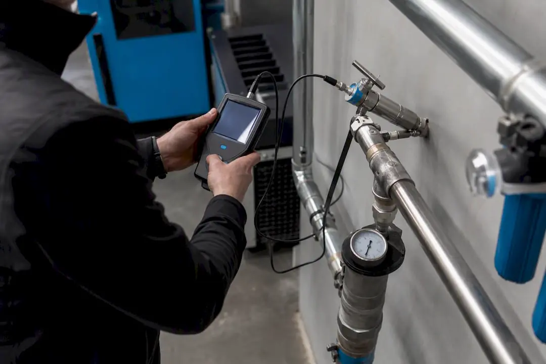
The real value of an audit lies in the action plan, not in the report itself. A company that has an audit prepared and then ignores the recommendations for half a year has wasted its money. Conversely, an operation that fixes the identified leaks and adjusts the working pressure within a few weeks often covers the cost of the audit even before the first subsidy payment arrives.
A second thing that conventional advice underestimates: the price of an audit should not be measured only against the size of the operation, but against the age of the compressor station. A ten-year-old distribution system without upgrades hides more reserves than a recently modernized station, so even a more expensive comprehensive audit pays off faster there. The priority should be to determine the state of leaks and pressure settings, and only then address whether new technology is needed.
— Zdeněk
Consultation and further steps with Kompresory-vzduchotechnika
Kompresory-vzduchotechnika offers exactly the combination an audit requires: a technical team that can design the measurement, evaluate the data, and directly supply and install the solution, without you having to look for another contractor to implement the measures.
After the audit evaluation, the next steps usually involve fixing leaks, adjusting filtration, or replacing dryers. The compressed air filtration range according to ISO 8573 covers exactly this part of the measures, and for older machines it is often worth considering a more modern compressor with lower consumption.
If you would like an indicative price calculated for your specific operation, simply contact Kompresory-vzduchotechnika with an overview of the number of compressors, their age, and approximate annual energy consumption. Based on these details, the team will propose the scope of measurement and arrange a non-binding consultation directly at your facility.

Verified sources and standards for further study
To verify the technical parameters of the audit, the standard ČSN ISO 50002 applies, which defines the procedure and scope of energy audits. Documentation for the OP TAK and OPŽP subsidy programs contains specific requirements for what an audit must include to be recognized as part of an application. Expert articles on the Kompresory-vzduchotechnika website, such as compressor diagnostics or utilization of waste heat, add practical context to the measures proposed in the audit.
Frequently asked questions
How much does a compressor energy audit cost?
A comprehensive audit of a compressor station in an industrial facility in Czechia usually costs between 25,000 and 200,000 CZK, depending on the scope of measurement and the number of machines, while a quick virtual screening can be obtained for just a few thousand crowns.
How much does an energy assessment of a building cost?
An energy assessment of a simple building starts at roughly 60,000 CZK, while for larger complexes with multiple buildings, the price increases depending on the complexity of the technologies and the need for additional measurements.
How long does an audit of a compressor station take?
The measurement itself takes days to weeks, while the entire process from inquiry to delivery of the final report usually takes several weeks.
Is an audit worthwhile for smaller operations as well?
Yes, even operation with a single compressor can often reveal leaks and incorrect pressure settings through an audit, and fixing these pays off faster than in large facilities, because the initial investment in the audit tends to be lower.
Can the audit serve as a basis for a subsidy?
An audit prepared in accordance with ČSN ISO 50002 serves as an official technical basis for the OP TAK and OPŽP programs, which reduces the net costs of implementing the proposed measures.
Recommended

Noise level of a screw compressor: what do the numbers on the label mean
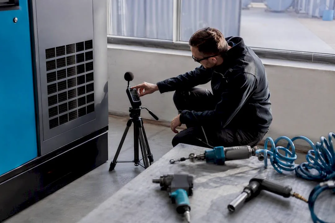
A screw compressor typically produces a sound power level (Lwa) in the range of 79 to 90 dB(A), while the sound pressure level (Lwp) at the workplace tends to be 59 to 70 dB(A). These two values are not the same, and confusing them is the most common mistake when comparing models. The first step is therefore to determine which quantity the manufacturer states on the label, and then carry out your own measurement directly on site, because the installation and the acoustics of the space can significantly shift the actual value. Standards for noise measurement and expert consultations on this topic are also offered by Kompresory-vzduchotechnika.
In brief:
- The manufacturer states different values for sound power (Lwa) and sound pressure (Lwp), which must be verified by your own measurement with regard to the installation site.
- Most compressors in operation reach a noise level of 59 to 70 dB(A) for pressure and 79 to 90 dB(A) for power, while the actual value in practical use tends to be 5 to 10 dB higher.
- The use of soundproof enclosures, anti-vibration pads, and proper pipe fastening can significantly reduce the spread of noise in the work area.
- When comparing catalog data, the measurement conditions and confirmation of the method used to determine the value must be requested, because without this, it is not possible to reliably track the actual noise level.
- Immediate measures for high noise levels include measurement, maintenance, and installation of noise-reduction elements, while investing in insulation without verifying the actual condition tends to be unnecessary.
Contents
- What do Lwa, Lwp, and dB(A) mean for a compressor
- What is the typical noise level of screw compressors in operation?
- How to compare compressor noise levels based on catalog data?
- How Kompresory-vzduchotechnika measures and addresses noise in practice
- When to address noise immediately and in what order to proceed
- Solutions for quieter compressor operation
- Useful resources for further reading
- Frequently asked questions
What Lwa, Lwp and dB(A) mean for a compressor
Sound power level (Lwa) describes the total amount of acoustic energy a machine radiates into its surroundings, regardless of distance. Sound pressure level (Lp, often written as Lwp), on the other hand, indicates how strongly the sound hits a specific point, typically one metre from the compressor housing. It is the difference between how much energy the source produces and what a person standing next to the machine actually hears.
The unit dB(A) is used because the "A" weighting filter mimics the sensitivity of the human ear, which does not perceive all frequencies with the same intensity. Without this filter, the numbers would not correspond to the actual subjective perception of noise.
Comparability of the data depends on the measurement conditions:
- the distance of the microphone from the source (usually 1 metre),
- the specific measuring point (front, side or top of the housing),
- the acoustic reflectivity of the room where the measurement takes place.
Two compressors with the same figure in the catalogue can therefore behave differently in practice. A unit placed in a small workshop with smooth walls will sound louder than the same model in a larger hall with sound insulation, even though the datasheets of both state an identical value.
What is the typical noise level of screw compressors in operation?
Approximate ranges for larger enclosed screw units are around Lwp 59 to 70 dB(A) and Lwa 79 to 90 dB(A). The spread is fairly wide, as it is influenced by motor power, enclosure design, and rotational speed.
Practical measurements in operation often reveal values 5 to 10 dB higher than catalog data — the reason is usually the placement of the machine, proximity to walls, or hard floors, which reflect sound instead of dampening it.
Enclosed units with an insulated housing are among the quieter solutions and are suitable for spaces where people work near the machine. Open installations, common in industrial halls with a central compressor room, do not limit noise in any way and rely on distance or structural insulation of the room. Mobile versions intended for construction sites tend to be noisier, as the compact design and lack of a soundproof enclosure increase the transmission of vibrations to the surroundings. This has a direct impact on the working environment. A noise level exceeding commonly accepted limits already requires hearing protection during full-shift exposure, while lower levels usually do not disrupt normal communication in the hall.
How to compare compressor noise levels based on catalog data?
The statement "noise level 70 dB" without further context has no value for comparison. You don't know whether it refers to sound power or pressure, nor under what conditions the measurement was taken. Likewise, a reference value of around 85 dB often appears in practice, which must always be verified in the same way, as it alone says nothing about the type of quantity.
Before comparing two models, request specific documentation from the supplier:
- the type of quantity stated (Lwa, or Lp),
- the distance and point of measurement,
- the type of enclosure (closed, open, soundproof box),
- motor speed and cooling method (air-cooled, oil-cooled),
- measurement protocol according to the relevant standard.
Request a measurement report that includes the measurement conditions, including the room geometry. Without it, models from different manufacturers cannot be directly compared, because each may have been tested under different conditions. An estimate of the real level at the installation site can be made with a simple calculation taking wall reflectivity into account, but an on-site operational measurement in the hall is always more accurate.
| Parameter to verify | Why it is key |
|---|---|
| Type of quantity (Lwa/Lp) | Distinguishes the source power from the impact at a specific location |
| Measurement distance | Affects the measured pressure value |
| Type of enclosure | A closed enclosure dampens noise more significantly than an open design |
| Motor speed | Higher speed usually increases flow noise |
| Measurement standard | Ensures comparability between manufacturers |
The acoustics of the premises themselves play a role that no catalogue will ever take into account. A hall with concrete walls and a high ceiling reflects sound differently than a workshop with acoustic ceilings, even with an identical machine. You can find a detailed overview of the technical advantages of different designs in the comparison of screw compressors for industry.
How Kompresory-vzduchotechnika measures and addresses noise in practice
The internal methodology is based on repeated measurements at a defined point (usually one metre from the housing, at a height corresponding to the operator), with several repetitions due to fluctuations in motor load. The measured data are compared with the manufacturer's data sheet and with the actual behaviour in a specific operation.
Practical interventions that have proven most effective in the field:
- installation of anti-vibration pads under the compressor feet,
- flexible mounting of piping so that vibrations are not transmitted into the distribution system,
- acoustic enclosures and boxes for units located close to residential areas,
- inspection and replacement of filters as part of regular maintenance, which prevents an increase in noise caused by flow.
Anti-vibration pads and proper pipe fastening are among the quickest and cheapest steps to reduce noise transmitted into the building structure. For technicians dealing with specific service tasks, the guide to bleeding a compressor is useful, as well as the overview of compressor noise reduction methods, which describes the technical measures in more detail.
When to address noise immediately and in what order to proceed
If the noise level endangers the operator's hearing or exceeds the limits for the working environment, act immediately. This is not an aesthetic problem, but a matter of work safety. If it is only a matter of comfort in a hall with no people nearby, you can proceed systematically without rushing.
The recommended sequence is clear: first measure the actual noise level on site, then check maintenance (filters, lubrication, bearings), then add anti-vibration mounting, and only as the last step address an acoustic enclosure or room insulation. Skipping the measurement and going straight to investing in insulation tends to be the most common unnecessary expense we have repeatedly seen with clients.
— Zdeněk
Solutions for quieter compressor operation
Lower noise levels in a screw compressor often start with the quality of air treatment and distribution, not just the motor itself. Kompresory-vzduchotechnika offers specific categories that help reduce both operating noise and the energy demands of the system.
Compressed air treatment units up to 18 bar limit turbulent flow in the distribution system, which is often one of the sources of noise. Filtration according to ISO 8573 reduces the load on the compressor and thus its noise level during long-term operation. For operations where energy savings are a priority, we offer SCR regulation for screw compressors, which limits unnecessary operation at high speeds, and for the most demanding applications also scroll compressors as a quieter alternative.
If you need to order an on-site noise measurement or a consultation on selecting a suitable unit, contact Kompresory-vzduchotechnika and arrange a date directly at your facility.
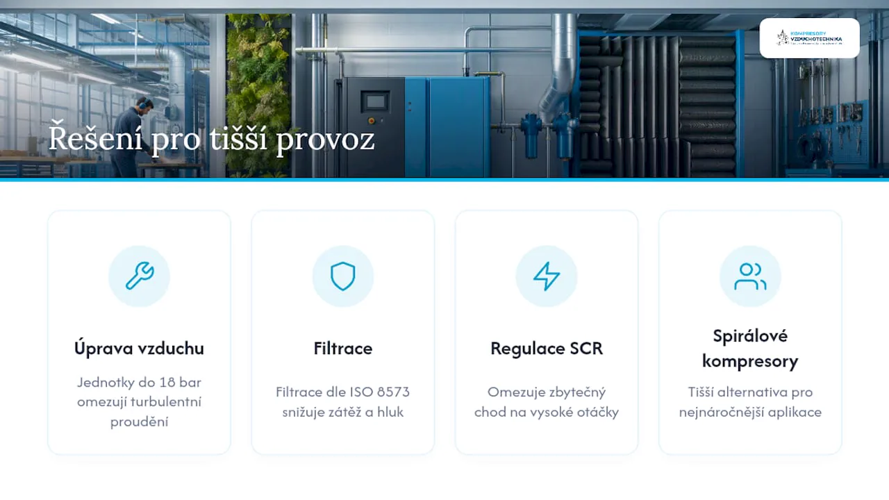
Useful resources for further reading
Details on technical interventions can be found in the overview of compressor noise reduction methods. Diagnosing leaks, which amplify noise, is described in the guide to repairing an air leak, and the broader context of health protection is summarized in the article on noise reduction in operations.
Frequently asked questions
How to reduce compressor noise?
The fastest effect comes from anti-vibration pads under the feet, flexible piping mounts, and regular filter replacement. For permanently noisy units, an acoustic enclosure or placement in a separate, insulated space helps.
How loud is a noise level of 40 dB?
The level corresponding to a quiet conversation or a calm office is significantly lower. Screw compressors typically operate significantly higher, with sound pressure typically between 59 and 70 dB(A).
What is the operating principle of a screw compressor?
Two interlocking rotors compress air through a continuous rotary motion in an enclosed space, without the pulsating motion of a piston. This principle leads to a more uniform air flow and a different noise character.
What is the difference between a piston compressor and a screw compressor in terms of noise?
Piston compressors generate more pronounced impulse noise due to the intermittent motion of the piston, while screw compressors produce smoother but more continuous vibrations. The choice between them therefore also depends on whether operator comfort sensitivity or long-term noise exposure is more important.
Recommended
- List of advantages of screw compressors for industry - Kompresory-Vzduchotechnika.cz
- Screw and piston compressors with 63 kW power input - Kompresory-Vzduchotechnika.cz
- Piston and screw compressors in professional design with 4.0 kW power input
- Screw and piston compressors with 132 kW power input - Kompresory-Vzduchotechnika.cz

Condensate Drains: Types, Selection, and Installation in Practice
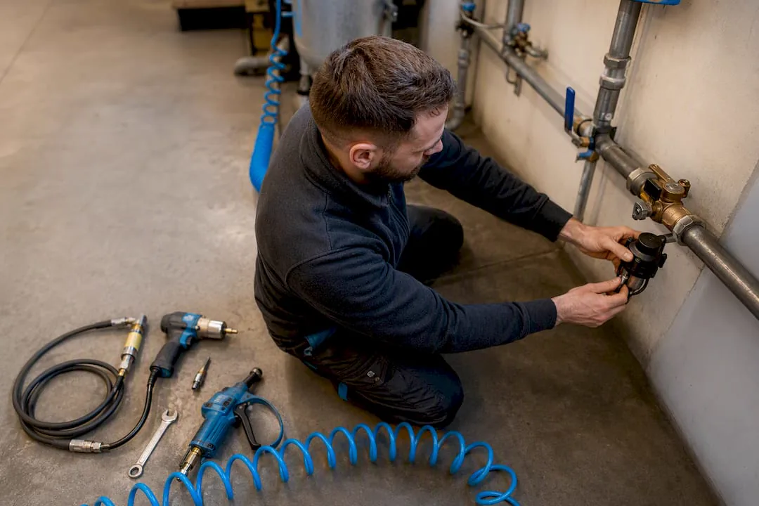
For most workshops, a mechanical float or zero-loss electronic drain is sufficient. For systems with oily condensate, an oil/water separator is unavoidable, regardless of the type chosen. Selecting the correct condensate drain depends on three things: the size of the installation, the contamination of the condensate, and the availability of power supply at the installation site.
Quick guidance by type of installation:
- Small workshops and service shops: a simple float or timer drain can handle the usual amount of condensate without the need for electronics.
- Medium-sized operations: electronic zero-loss drains save energy by discharging condensate only as actually needed, not according to a timer.
- Large industrial installations: a combination of robust electronic or magnetic drains with cyclonic water separators before dryers protects downstream equipment.
- Oily condensate: for oil-lubricated compressors, always add an oil/water separator regardless of the type of drain selected.
Key findings
The correct condensate drain is always based on the measured water production, the presence of oil, and the availability of power supply, not on the price of the cheapest model.
| Point | Details |
|---|---|
| Measure condensate production | Base it on the compressor output and relative humidity, not on a rough estimate. |
| Check the oil content | For oil-lubricated compressors, always add an oil/water separator. |
| Choose according to the size of the operation | Small workshops can manage with a float-type drain, medium and large operations require a zero-loss electronic type. |
| Install at low points | Installation below the air receiver and at the lowest points of the piping reduces the risk of filter clogging. |
| Consult on selection and installation | Kompresory-Vzduchotechnika.cz offers consultation, installation, and revision of the selected drain. |
Contents
- Types of condensate drains and how they work
- How to choose a drain: steps and checklist
- Where to install drains in a compressed air system
- Maintenance of Drains and Troubleshooting Common Faults
- Expert Background and Services of Kompresory-Vzduchotechnika.cz
- Influence of Temperature and Humidity on Drain Selection
- Specific Applications by Type of Operation
- What You Should Not Underestimate When It Comes to Drains
- Complete Compressed Air Treatment Solutions from Kompresory-Vzduchotechnika.cz
- Frequently Asked Questions
Types of Condensate Drains and How They Work
Condensate drains automatically remove water, oil, and impurities from the compressed air system, thus protecting the equipment from corrosion and loss of efficiency. There are five basic design principles on the market, and each one is suitable for a different operating situation.
Float (mechanical) drains operate without electricity. The float rises with the condensate level and opens the discharge valve once it reaches a certain level. Many models can discharge without air loss up to an operating pressure exceeding 10 bar, making them suitable even where no electrical connection is available. The disadvantage is sensitivity to mechanical impurities, which can clog the float or the valve seat.
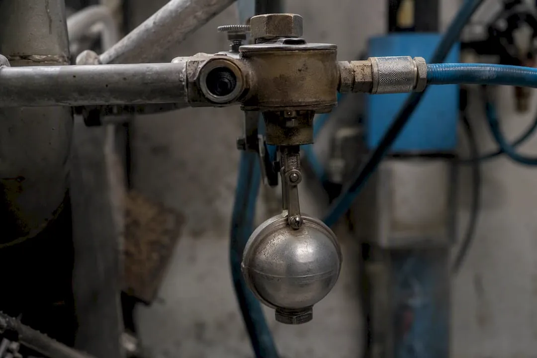
Timed drains discharge condensate at regular intervals set on a timer, regardless of the actual amount of condensate in the container. They are inexpensive and simple to install, but if the interval is set incorrectly, they unnecessarily discharge compressed air as well, which increases operating costs.
Electronic zero-loss drains (often referred to as IWD or EWD) use a condensate level sensor and discharge only as much condensate as has actually accumulated. This significantly minimizes compressed air waste compared to timed models. The capacity of modern zero-loss drains covers a wide range of condensate discharge rates suitable for both small and large compressor rooms, thus covering small compressors as well as large compressor rooms.
Magnetic drains use magnetically controlled valves that respond quickly and reliably even under fluctuating load. They are suitable where condensate production varies significantly during a shift.
Cyclone water separators are not drains in the true sense, but supplementary equipment. By using centrifugal force, they capture water aerosols from the air stream, thus protecting dryers and filters from overload.
Key parameter: zero-loss electronic drains bring the greatest savings in operating costs precisely in medium and larger operations, where the volume of discharged air with timer-based models noticeably worsens the energy balance.
When comparing types, monitor four technical parameters: maximum operating pressure, flow rate in m³/min, discharge capacity in litres per hour, and the material of the drain body. Cast iron or aluminium construction is sufficient for standard condensate; stainless steel construction is necessary where the condensate is aggressive.
How to choose a drain: steps and checklist
Choosing the right condensate drain is not about which model is "the best," but which one matches your operation. Follow the steps below.
- Estimate condensate production. This is roughly based on compressor output, operating time, and relative humidity of the air at the installation site. A more humid environment and higher output mean a larger volume of condensate, and therefore a need for a drain with higher discharge capacity.
- Determine whether the condensate is oily. For oil-lubricated compressors, a combination of a drain with an oil/water separator is recommended. Compact filtration units can significantly reduce the oil content, which helps meet requirements for environmentally compliant disposal.
- Take operating pressure and air losses into account. If energy savings are key for you, prefer a zero-loss electronic solution over a timer-based model.
- Check power supply availability. Where electricity is not available or its connection is costly, a mechanical float drain remains a practical choice.
- Check connections and material. For aggressive condensate (for example, from oil compressors with specific additives), choose stainless steel construction instead of standard cast iron.
- Verify service access and availability of spare parts. A drain located in a hard-to-reach place will complicate routine maintenance and replacement of worn parts.
Professional tip: For systems with significantly fluctuating load, typically in multi-shift operations with variable air consumption, choose a drain with adaptive electronic control. It responds to the actual volume of condensate in real time and minimizes losses even under sudden load.
Where to install drains in a compressed air system
The placement of the drain determines whether it will work reliably or become a source of recurring faults.
- Install below the air receiver, on the bottoms of filters and separators, and at the dryer outlet, i.e. at all points where condensate naturally accumulates.
- Place drains at the lowest points of the pipeline route. Installation at low points significantly reduces the risk of condensate accumulation and subsequent clogging of filter elements.
- Ensure sufficient access for servicing. A drain built into a tight space without the possibility of disconnection will slow down any future inspection.
- Make sure the pipeline has a proper slope toward the outlet so that condensate does not stagnate and form pockets before the drain itself.
- Avoid locations with strong vibrations (near piston units) and uninsulated piping with high condensate temperature. Before installation, also check the safe procedure according to the guide for depressurizing pressurized vessels.
Maintenance of drains and troubleshooting common faults
The condensate drain is one of the components that is easily forgotten until it starts to fail. Regular inspection, however, takes only a few minutes a month.
- Check the seals, strainer, solenoids, and float at least once a month, more often in dusty operations.
- Test the drain function by manually triggering the cycle and watch whether the drain actually closes after discharging the condensate.
- Measure air losses by listening or using an ultrasonic detector, a leak at the drain indicates a worn seal or a clogged valve seat.
- Address clogging by cleaning the strainer and the drain outlet, common in operations with a higher proportion of solid impurities in the condensate.
- Check for freezing in uninsulated outdoor piping during winter, a frozen drain stops functioning completely.
- Check the sensor function on electronic models, if the drain does not discharge at all or, conversely, discharges continuously.
Work on a pressurized system is always preceded by safe depressurization according to the internal procedure, see the guide to the compressor venting procedure.
Professional tip: A leaking drain is often mistakenly thought to be a compressor fault. Before you start looking for a leak elsewhere in the piping, check the drain valve of the condensate drain first, it tends to be the cheapest and fastest repair in the whole system.
Professional background and services of Kompresory-Vzduchotechnika.cz
Choosing a condensate drain is only part of the overall care of a compressed air system. Kompresory-Vzduchotechnika.cz provides:
- expert consultation on choosing the type of drain according to the specific operation and type of condensate,
- installation, inspections, and energy audits of compressor stations,
- service support for resolving leaks and faults in compressed air piping.
For operators dealing with the legislative side of condensate disposal, an overview of legal obligations for operators in the Czech Republic is useful. When dealing with air leaks in the system, the practical guide to repairing leaks will help, and when planning a new compressor room, it is worth consulting the requirements for compressor room layout.
Influence of temperature and humidity on condensate drain selection
Temperature and relative humidity of the air at the compressor intake point directly affect the amount of condensate that the drain must handle. The warmer and more humid the air drawn in by the compressor, the more moisture is precipitated during compression and subsequent cooling. In the summer months, the same compressor therefore produces significantly more condensate than in winter, and a drain sized for winter operation may fall short in summer.
In facilities with high humidity (for example near paint shops, washing stations or food processing plants with steam), it is worth choosing a drain with higher discharge capacity, ideally an electronic zero-loss type, which adapts to fluctuating production without manual readjustment.
Low temperatures bring the opposite problem: the risk of condensate freezing in the discharge piping or directly in the drain body. Outdoor installations and uninsulated plant rooms require either heat tracing of the piping or placing the drain in a heated space during winter months. Temperature fluctuations between day and night shifts also stress the seals and float mechanisms, shortening their service life.
When designing the system, therefore, do not assess condensate production based on a single annual average figure, but according to the most demanding scenario, i.e. a hot and humid summer. A drain that can handle the peak will have no problem handling normal operation.
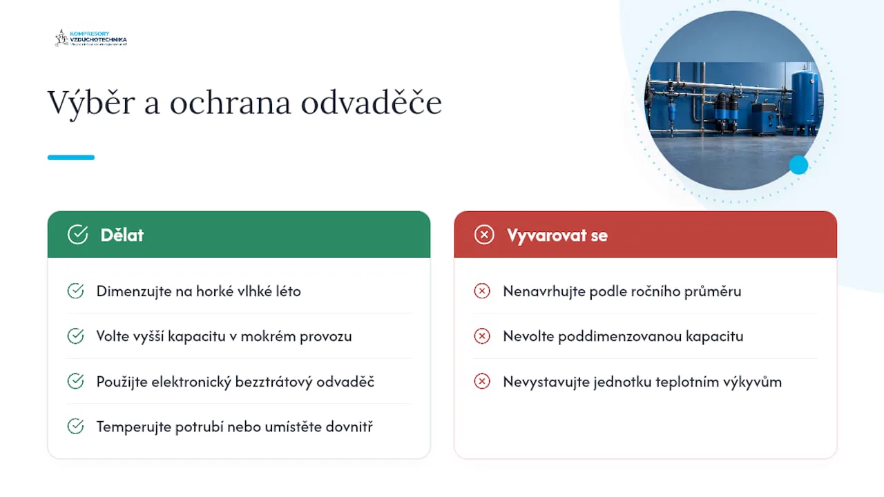
Specific uses by type of facility
In practice, the choice of drain varies depending on the industry and nature of production.
Car repair shops and paint shops usually work with smaller piston or screw compressors and condensate with a higher oil content from lubricated units. Here, a combination of a simple float drain with a compact oil/water separator directly under the filtration unit has proven effective.
Food and pharmaceutical facilities place emphasis on reliability and hygiene. An electronic zero-loss drain with a stainless steel body eliminates the risk of contamination here while also meeting stricter requirements for compressed air cleanliness according to filtration governed by the ISO 8573 standard.
Engineering facilities with oil-free screw compressors usually need a more robust solution with higher discharge capacity, especially where several compressors run in parallel into a shared air receiver. Here, it is worth using a magnetic or electronic drain placed directly under the air receiver and a second one after the dryer.
Construction and mobile applications with portable compressors often manage with simple timed or manual draining, since the condensate volume tends to be low and access to the unit is easy.
For facilities with higher requirements for air cleanliness, the choice of drain is complemented by appropriately sized compressed air filtration according to ISO 8573, which reduces the load placed on the drain itself.
What You Shouldn't Underestimate About Condensate Drains
The most common mistake I see in operations is not choosing the wrong type, but underestimating the combination with an oil separator. Technicians often select a drain based only on pressure and flow, completely forgetting about the oil content in the condensate, until the inspection authority or waste disposal contractor sends back a report with a high hydrocarbon content.
The second underestimated issue is service accessibility. A cheaper drain installed in a poorly accessible location ends up costing you more, because the technician can only reach it during a shutdown, not during a routine round. The conventional advice "buy the cheapest float model" only works where the condensate is clean and the operation is small. For medium and larger installations, the investment in a zero-loss electronic drain pays off through energy savings, not through the price of the unit itself.
If I have to give one priority, it's this: first measure the actual condensate production and check for the presence of oil, only then compare types and prices. Without this step, you're choosing blindly.
— Zdeněk
Complete Solutions for Compressed Air Treatment from Kompresory-Vzduchotechnika.cz
Kompresory-Vzduchotechnika.cz offers a comprehensive range for condensate drainage and treatment, so you don't have to combine parts from several suppliers and deal with incompatible connections. The offer includes compressed air treatment units up to 18 bar for standard operation as well as metal treatment units for more demanding conditions, including automatic drains with oil/water separators.
In addition to selling units, Kompresory-Vzduchotechnika.cz also offers installation and inspection booking directly through the e-shop or service line, so a single partner handles the selection, installation, and subsequent functionality check. If you're not sure which type of drain your operation needs, a consultation with a technician will save you time and potential complaints. Take a look at the complete range of compressed air treatment units and choose a solution matching your operating pressure and condensate volume.
Frequently Asked Questions
Which type of condensate drain is the most reliable?
A mechanical float drain is the most reliable where no power supply is available, because it works purely mechanically without electronics. In medium and large operations, however, zero-loss electronic drains better control operating costs by minimizing air losses.
How often does a condensate drain need to be serviced?
Checking the seal, strainer, and drain mechanism is recommended at least once a month, more often in dusty or humid operations. Electronic sensors should be tested at every regular inspection of the compressor station.
Do I always have to use an oil/water separator?
If the compressor operates with oil lubrication, an oil/water separator is required regardless of the type of drain chosen. Compact filtration units can significantly reduce oil content and help meet requirements for environmentally compliant disposal.
Where is a condensate drain most commonly installed?
Drains are installed below the air receiver, on the bottoms of filters and separators, and at the dryer outlet, i.e., in all places where condensate naturally accumulates. Installation at the lowest points of the piping also reduces the risk of clogging the filter elements.
Where can I get expert help choosing a drain?
Kompresory-Vzduchotechnika.cz offers consultation on selecting the appropriate type based on the specific operation, as well as installation and subsequent inspections of the compressor station. The company also provides technical support for resolving common faults in drains and compressed air distribution systems.
Recommended
- Condensate from the compressor: Czech Republic laws for operators - Kompresory-Vzduchotechnika.cz
- Factors for selecting an industrial compressor: a 2026 guide - Kompresory-Vzduchotechnika.cz
- Basic requirements for a compressor room: guide 2026 - Kompresory-Vzduchotechnika.cz
- Checklist of compressor accessories: a guide for technicians - Kompresory-Vzduchotechnika.cz

Sizing of compressed air distribution: procedure and key figures
Sizing of a compressed air distribution system is governed by one main rule: the pressure drop between the compressor and the most distant point of use should be as low as possible and kept at a low level. The second rule concerns flow velocity; the main distribution lines are designed so that the velocity stays within a reasonable limit, which protects the system from carrying water and impurities.
The procedure is always the same. You determine the actual air consumption (FAD) of all connected equipment, measure the total pipe length including the equivalent length of fittings and valves, select an approximate diameter from a table or nomogram, and verify the result with a more precise calculation using the Darcy-Weisbach equation.
Key figures for quick orientation:
- The pressure drop should be as low as possible and kept at a low level between the compressor room and the most distant point of consumption
- The recommended velocity in main lines is within a reasonable range, typically around several metres per second
- The velocity in end branches and connections should be lower, adapted to the given section
- The upper velocity limit is set to prevent condensate and impurities from being carried through the piping
Key findings
Correct sizing of a compressed air distribution system consists of maintaining a pressure drop of up to 0.1 bar and a flow velocity of 6 to 7 m/s in the main line, confirmed by calculation and measurement after installation.
| Point | Details |
|---|---|
| Pressure drop limit | Keep the pressure drop between the compressor and the farthest outlet below 0.1 bar. |
| Design velocity | Main lines 6–7 m/s, branch connections 2–4 m/s, absolute maximum 9 m/s. |
| Equivalent lengths | Add the length for each elbow, valve, and T-piece to the actual pipe length. |
| Table and calculation | Tables give a quick estimate, the Darcy-Weisbach equation confirms accuracy for complex networks. |
| Implementation with a specialist | Kompresory-vzduchotechnika provides design, installation, measurement, and service of the distribution system all in one place. |
Contents
- Practical procedure for sizing the air distribution system step by step
- When a table is enough and when an exact calculation is necessary
- What effect does air velocity have on pressure losses
- Selecting pipe and fitting materials for compressed air distribution
- How to verify distribution sizing by measurement after installation
- What makes good sizing truly good
- How Kompresory-vzduchotechnika can help you implement the design
- Frequently asked questions
Practical procedure for sizing an air distribution system step by step
Sizing an air distribution system is not a guess by eye. It is a sequence of five steps that build on one another, and skipping any step usually shows up as low pressure at the end of the line or, conversely, as unnecessarily expensive oversized piping.
- Compile a list of consumption points. For each pneumatic device, determine the actual consumption in l/s or m³/h, not the nominal output from the catalog. In larger facilities, simultaneity of consumption must be taken into account, as not all tools run at the same time.
- Divide the network into sections. The main distribution line, risers, and service connections have different requirements for velocity and permissible pressure drop, so do not size them uniformly.
- Calculate the total and equivalent length. Add the equivalent length for each elbow, T-piece, valve, and reducer to the length of straight pipe. In shorter, densely fitted sections, fittings often account for a larger part of the pressure loss than the straight run itself.
- Choose a rough diameter. Sizing tables, with flow on one axis and pipe run length on the other (typically columns for 25, 50, and 100 meters), give a quick initial estimate of the diameter without having to calculate anything by hand.
- Refine with calculation and verify the velocity. The Darcy‑Weisbach equation with the Reynolds number and pipe wall roughness gives the exact pressure loss. Check that the resulting flow velocity remains within the recommended range for the given section.
You can also verify the specific implementation of the main distribution system using the example of 50 mm air piping systems for industrial operations, where you can see how the sizing translates into the actual performance of the network. The entire installation sequence from design to installation is then described in the guide how to set up a compressed air distribution system step by step.
Professional tip: In step 3, keep a table of equivalent lengths for each fitting separately. For short service connections with several elbows and a ball valve, this sum can surprisingly increase the resulting pressure drop even where a straight run would show no problem.
When a table is enough and when an exact calculation is necessary
The choice of method depends on the size of the project and how much margin for error you have in the budget. For smaller workshops, service operations, or a simple addition to an existing line, a table-based or nomogram-based approach is usually fully sufficient. Sizing tables, such as those published by Czech sources like EQOfluids, work with the relationship between flow rate, line length, and recommended diameter, and give a usable result within a few minutes.
For larger industrial networks, where the consumption of dozens of machines is summed up and the line runs through multiple floors or halls, the table-based estimate becomes inaccurate. This is where an exact calculation comes in:
- The Darcy‑Weisbach equation calculates the pressure loss from the flow velocity, pipe length, diameter, and friction coefficient.
- The Reynolds number determines whether the flow is laminar or turbulent, which affects the choice of friction coefficient.
- The roughness of the inner pipe surface is entered into the formula according to the material, steel piping has a different roughness than plastic or aluminum.
A table gives you a quick estimate. A calculation gives you the certainty that the estimate holds for your specific material, line shape, and operating conditions. For critical operations, this step cannot be avoided.
To verify the result, it is worth using an online pipe hydraulic resistance calculator that works with the Darcy‑Weisbach equation and a list of fittings. Such a tool will confirm within moments whether the table-based diameter estimate matches the exact calculation, or whether the dimension needs to be increased. Combining both methods, a table for the initial estimate and a calculation for confirmation, is in practice the fastest way to a reliable design.
What effect does air velocity have on pressure losses
In practice, pressure drop is not distributed evenly along the entire length of the network. A reasonable distribution looks like this:
- Main line from the compressor room: the lowest share of the drop, with some design procedures recommending keeping it below 0.03 bar
- Distribution branches to individual halls or sections: medium share of the total drop
- Service connections to individual machines: the remaining reserve up to the overall limit of 0.1 bar
A high flow velocity above 9 m/s brings three specific problems. It increases the noise level of the distribution system, which is particularly noticeable with metal pipes routed along the walls of halls. It allows condensate and mechanical impurities to be carried further into the system, which puts a load on filters and end devices. And finally, it increases the pressure loss with the square of the velocity, so even a small oversizing of the pipe flow results in a disproportionately large pressure drop and thus also higher energy consumption of the compressor.
When designing the main distribution line, it pays off in the long term to choose a diameter one size larger than current consumption indicates. Expanding production with additional machines is common, and a subsequent pipe replacement will always cost more than the initial reserve. The relationship between pipe diameter and operational efficiency is also well described by the guide to industrial air distribution focused on operational efficiency.
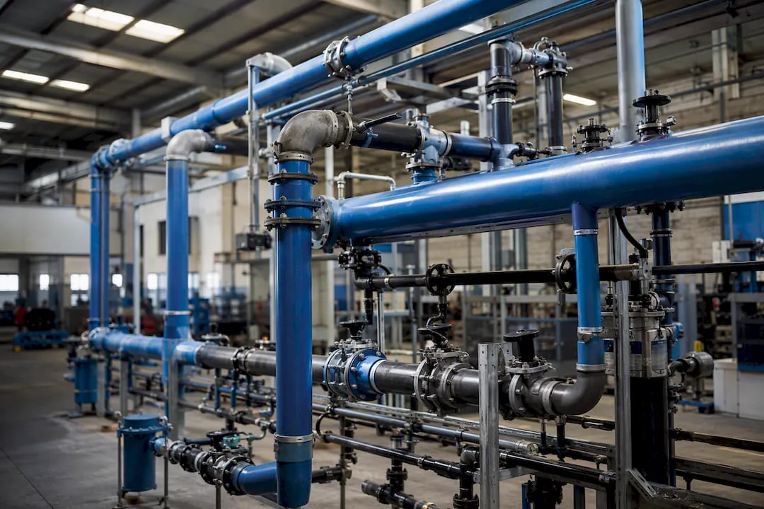
Selecting pipe material and fittings for the compressed air distribution system
The pipe material affects the roughness of the inner surface, and thus directly enters into the calculation of pressure loss. At the same time, it determines the resistance to corrosion and the overall service life of the distribution system.
- Steel pipe is mechanically durable, but without a surface treatment it is subject to corrosion, which shows up as increased surface roughness and, over time, also as higher pressure losses.
- Stainless steel pipe has the best corrosion resistance, is suitable for operations with high humidity or aggressive environments, but the price is higher.
- Aluminum pipe combines low weight, a smooth inner surface, and good corrosion resistance; installation is faster thanks to the lower weight of the components.
- Plastic systems have very low surface roughness and are resistant to corrosion, but their use is limited by the maximum operating pressure and temperature according to the manufacturer's specifications.
For push-in and quick-assembly systems, it is worth looking at the range of push-in pipe systems, which simplifies the selection of materials and fittings. Keep the number of elbows, tees and valves on the line to a minimum, as each fitting adds an equivalent length to the pressure drop calculation, and for short sections this can mean the difference between a compliant and a non-compliant design.
How to verify the pipework sizing by measurement after installation
A design on paper is one thing, actual operation is another. Verification is carried out in three steps:
- Measure the pressure at key points. Using a pressure gauge or differential pressure sensor, compare the pressure at the compressor room outlet and at the farthest point of use under full operating load.
- Compare the measured difference with the design limit of 0.1 bar. If the deviation is within a tolerance of a few hundredths of a bar, the design is correct. A more significant deviation indicates an undersized section, a clogged fitting, or a leak.
- Record the results in the handover protocol. For larger installations, it is worthwhile to note the measured values of pressure, temperature, and possibly flow velocity in individual sections, so that the data can be revisited in case of future network expansion.
Professional tip: Always measure during actual consumption, not in an idle state without load. A pipework system that is compliant without load can easily exceed the 0.1 bar limit during full operation of several machines at once.
Author Zdeněk's experience: common mistakes and installation tips
The most common recurring mistakes in practice are: underestimating the equivalent length of fittings, sizing based on the nominal output of tools instead of actual consumption, and using a single diameter for the entire network regardless of the different requirements of the main line and branch connections.
Before ordering pipework, check this checklist:
- Have you summed up the actual consumption of all outlets, taking simultaneity into account?
- Did you account for the equivalent length of each fitting on the line?
- Does the selected diameter correspond to the recommended velocity of 6–7 m/s in the main line?
- Do you have a reserve in diameter for future expansion of operation?
During installation, minimize the number of unnecessary elbows, mount the piping so that no stress arises in the joints, and after commissioning check all threaded and pressed joints with a leak detector.
What makes good sizing truly good
The most common mistake I see in distribution system designs is not a wrong formula. It is underestimating the equivalent length of fittings and overestimating the accuracy of tables for complex networks with many branches. A table is an excellent tool for an initial estimate, but on a route with ten elbows and five valves over twenty meters, it will give a distorted result unless the fittings are counted honestly.

The second thing that conventional advice underestimates: a reserve in diameter almost always pays off. Investing in pipework one size larger is a fraction of the cost of later replacing the entire line when operations expand with additional machines. If you have to choose between "exactly according to the calculation" and "with a small reserve for expansion", choose the reserve for the main line.
The reader's priority should be clear: first correctly determine the actual consumption (not catalog values), then account for equivalent lengths, and only at the end decide whether a table is sufficient or an exact calculation according to the Darcy-Weisbach equation is necessary. The reversed order of priorities is the reason why undersized distribution systems appear so often.
— Zdeněk
How Kompresory-vzduchotechnika will help you implement the design
A design on paper is half the work; the other half is correct implementation and air quality at the end of the pipeline. Kompresory-vzduchotechnika offers turnkey distribution system design, on-site pressure drop measurement, installation, and subsequent service, so you don't have to combine several suppliers for one project.
The calculated pipe diameter is usually also linked to the choice of air treatment at the end of the route. In our offer you will find compressed air treatment units up to 18 bar as well as a filtration program according to the ISO 8573 standard, which addresses air quality according to the actual requirements of end equipment. If you are still choosing a suitable compressor for the designed distribution system, also browse the category of piston and screw compressors.
For a non-binding inquiry, prepare the basic data from the checklist: total air consumption (FAD) in l/s or m³/h, lengths of individual pipe sections, number and type of outlet points, and an approximate plan for future expansion of operations. With this data, the technicians at Kompresory-vzduchotechnika will design the distribution system dimension and suitable air treatment tailored to your operation.
Frequently Asked Questions
What is the maximum permissible pressure drop in the distribution system?
The target value is 0.1 bar between the compressor and the most distant point of use; for the main line, it is recommended to keep significantly below this limit.
What is the recommended flow velocity in compressed air piping?
Main distribution lines are designed for 6 to 7 m/s, end connections tend to be slower, around 2 to 4 m/s, and the limit of 9 m/s must not be exceeded due to the risk of condensate entrainment.
When should a table be used and when is an exact pipe sizing calculation needed?
A table or nomogram is sufficient for smaller and simpler distribution systems; for extensive industrial networks with many branches, the result must be verified using the Darcy-Weisbach equation.
How does the equivalent length of fittings affect the calculation?
Every elbow, valve, or T-piece is included in the calculation as additional length of straight pipe; in short, densely fitted sections, this often accounts for a greater part of the pressure loss than the route itself.
Can Kompresory-vzduchotechnika help with distribution system sizing?
Kompresory-vzduchotechnika offers turnkey distribution system design, pressure loss measurement, and installation, so both the technical calculation and the implementation can be secured from a single supplier.
Recommended
- How to set up compressed air distribution step by step - Kompresory-Vzduchotechnika.cz
- Procedure for assembling air distribution: an installation guide - Kompresory-Vzduchotechnika.cz
- Guide to industrial air distribution: operating efficiency - Kompresory-Vzduchotechnika.cz
- Benefits of centralized air distribution in industry - Kompresory-Vzduchotechnika.cz

Compressed air leak detection: rapid location of losses
We have merged this article with a more detailed and more up-to-date guide on the same topic. Continue here: How to eliminate air leaks: a guide for a 42% energy saving.

Compressed air for CNC: what it must meet for reliable operation

For reliable CNC machining, you need dry, clean, and correctly sized compressed air. Without a dryer and multi-stage filtration, moisture and oil particles will sooner or later get into pneumatic components, sensors, and the cutting zone. The standard for assessing air quality is ISO 8573, which defines purity classes according to the content of solid particles, water, and oil. A key parameter is the dew point, whose continuous monitoring (for example with a SUTO S217 sensor) reveals a problem before it shows up on the workpiece.
Before changing anything, check these four things:
- Pressure – matches the current machine specification setting and is stable even under load.
- Flow – the compressor covers the peak consumption of all appliances running simultaneously.
- Dew point – the air is sufficiently dry for the given ISO 8573 class.
- Leaks – the distribution system shows no audible or measurable pressure losses.
Key findings
Reliable operation of a CNC machine depends on a combination of dry and clean air, a correctly sized compressor, and regular measurement of consumption and leaks.
| Point | Details |
|---|---|
| Air quality takes priority | A dryer and multi-stage filtration according to ISO 8573 prevent damage to sensors and tools. |
| Monitor the dew point continuously | A sensor such as the SUTO S217 with an alarm detects the problem before a defective part is produced. |
| Measure before purchasing a compressor | Actual consumption and leaks determine the required output better than an estimate based on machines. |
| VSD only within the efficient range | Continuous speed control pays off at loads ranging from 50 to 80% of output. |
| Address leaks as the first step | Fixing leaks and measuring consumption brings energy savings of up to around 35%. |
| Comprehensive solutions from Kompresory-vzduchotechnika | The e-shop offers dryers, filtration, compressors, and hoses, along with design, installation, and energy audit services. |
Contents
- What role does compressed air play in CNC machining
- What air treatment is essential for CNC
- How to correctly size a compressor for CNC machines
- How to size the air distribution system and select accessories
- How to deal with leaks, condensate, and oil contamination
- How to increase the energy efficiency of compressed air
- Installation and operation checklist according to Kompresory-vzduchotechnika
- What I would address first when modernizing an air system
- Where to order air treatment and service for CNC operations
- Frequently Asked Questions
What function does compressed air serve in CNC machining
Compressed air in CNC machining performs three basic functions: it removes chips from the cutting zone, blows off the tool during tool changes, and cleans clamping surfaces before the workpiece is secured. Each of these has a direct impact on the result.
Insufficient chip removal means that fragments return into the cut, scratch the surface, and shorten tool life. In precision operations (engraving, micro-machining), the stability of the air stream matters just as much as its force, not just its strength.
- Chip blow-off improves surface quality and reduces tool wear.
- Blow-off during tool change protects the taper and the holder from contaminants that would cause inaccurate clamping.
- Cleaning the clamping surfaces before the workpiece prevents zeroing errors and uneven clamping.
Air cannot replace liquid cooling in operations with high thermal load, deep drilling, or machining of hard-to-machine materials, where the heat needs to be dissipated by a medium with higher thermal capacity. However, where chip removal and surface cooling are sufficient, air is the cheaper and faster choice.
Moisture and residual oil in the piping have a worse impact on CNC machines than expected: they clog nozzles, damage electropneumatic valves, and distort the signal from optical and inductive sensors. CNC machine manufacturers therefore often specify a requirement for the quality of the supplied air in their technical documentation, and if the supplier fails to meet this specification, problems such as claims and unplanned downtime can occur.
What air treatment is essential for CNC
Air treatment has three layers: drying, filtration, and continuous quality monitoring. Omitting one of them usually means the problem appears later and at a higher cost.
Condensation dryers reduce the dew point to values suitable for common pneumatic actuators and blow-off. Adsorption dryers go deeper and are necessary where the process requires a very low dew point, typically in precision machining, painting lines following CNC production, or machines with sensitive optics.
Filtration should have a multi-level structure:
- a condensate separator right after the compressor,
- a coarse filter capturing solid particles and oil droplets,
- a final filter for submicron particles before entering the machine.
A statistic that is often overlooked: combining a dryer with multi-stage filtration according to the ISO 8573 filtration program significantly reduces the risk of contamination of sensitive CNC components – a separator, coarse and fine filter together with a dryer form the minimum standard, not an above-standard solution.
Continuous dew point monitoring complements the treatment with real-time control. Sensors such as SUTO S217 allow you to set a two-level alarm that warns of an approaching problem and, in extreme cases, automatically cuts off the air supply before moist air damages the tool or workpiece. For operations with high quality requirements, this is a simple safeguard against scrap rate.
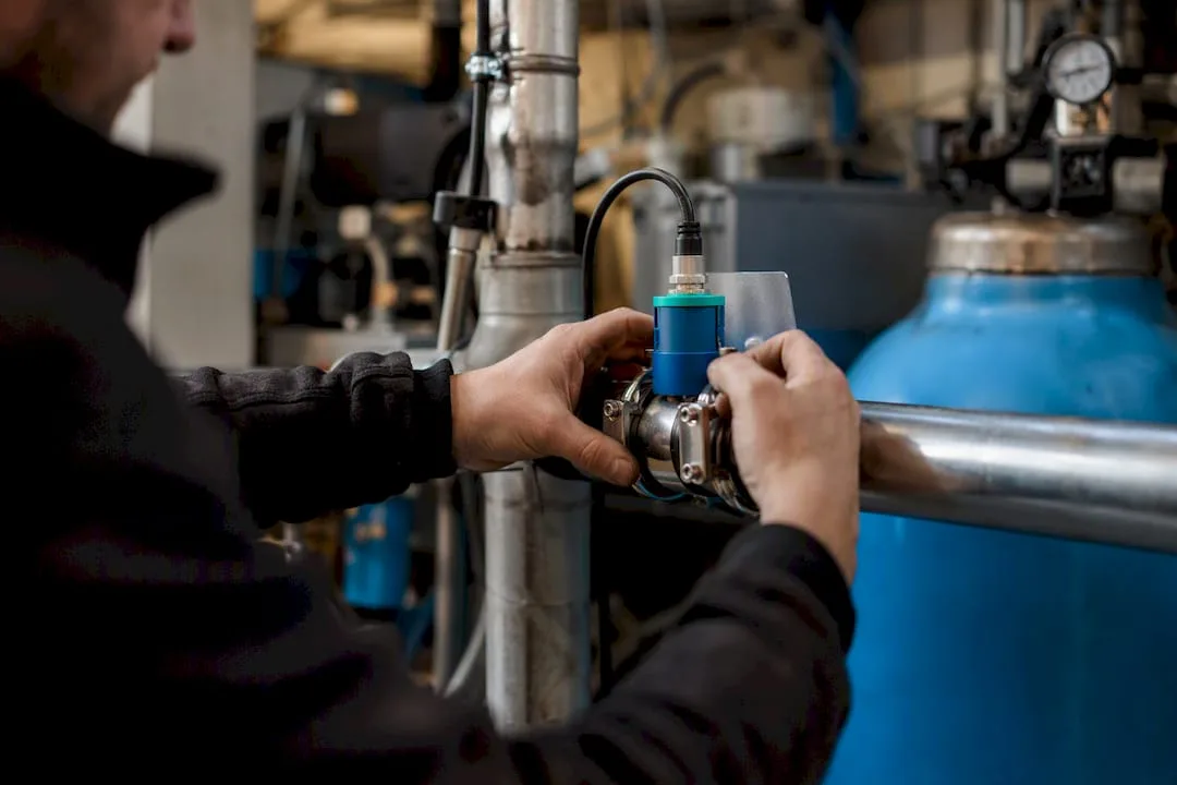
How to properly size a compressor for CNC machines
The basis is to measure, not estimate. Before you buy a new compressor for CNC machines, determine the actual air consumption, peak flow, and the level of leaks in the current distribution system. Without this step, it's easy to end up with a new compressor that is either undersized during peaks or permanently oversized and inefficient.
- Measure the actual consumption over a typical working cycle, including peaks when multiple machines are running simultaneously.
- Estimate future growth in consumption if you plan to expand production – underestimating this step is one of the most common mistakes in sizing.
- Consider the technology: a screw compressor with continuous speed control (VSD) is suitable for continuous operation with variable load, while an oil-free solution is suitable where traces of oil would compromise process quality.
- Set a power reserve – usually 15 to 25% above the measured peak, never double it "just to be safe."
A VSD compressor makes sense where the load fluctuates and the unit will most often operate in the mid-range of its output. Outside this range, the inverter's efficiency is lost, and the investment in VSD won't pay off as quickly as expected.
Professional tip: Don't plan the compressor based on the nameplate output of the machines in the shop. Measured consumption tends to be lower, because the machines don't run at full air draw simultaneously throughout the entire shift.
How to size the air distribution system and choose accessories
Pressure losses in the distribution system most often occur due to undersized hoses and the number of connections, not the length of the piping itself. Technicians' forums confirm that the choice of hose cross-section and the number of quick couplings have a real and often underestimated effect on pressure loss.
- For common CNC applications, hoses with a dimension of 8/6 mm have proven effective, while 10/8 mm is suitable for longer runs or higher flow.
- Hoses with textile or metal braiding can withstand higher temperatures and resist abrasion better than smooth profiles.
- Place push-in fittings as close to the consumer as possible and choose types with low pressure drop.
- Every joint is a potential leak point – minimize their number on the main line.
How to deal with leaks, condensate, and oil contamination
In practice, an air leak is usually detected by ear before any instrument picks it up, but for accurate assessment, measuring the pressure drop in a section of the distribution system that is shut off during downtime helps.
- Check for leaks using an ultrasonic detector or a simple overnight pressure drop test.
- Ensure condensate drainage through automatic drain valves, never by manually opening a valve once in a while.
- Replace filters according to the interval recommended by the manufacturer, not only once visible clogging appears.
- Check the solenoid valves – a delayed response or leakage indicates worn seals.
Professional tip: Do you keep a daily record of the pressure drop in the system? Even a small but persistent drop with no obvious cause is often the first sign of a developing leak.
When it's time to replace components rather than just service them: if a filter loses permeability faster than before after cleaning, or if a dryer fails to reach its declared dew point even after servicing, it is more economical to replace the component than to keep funding operation through repairs.
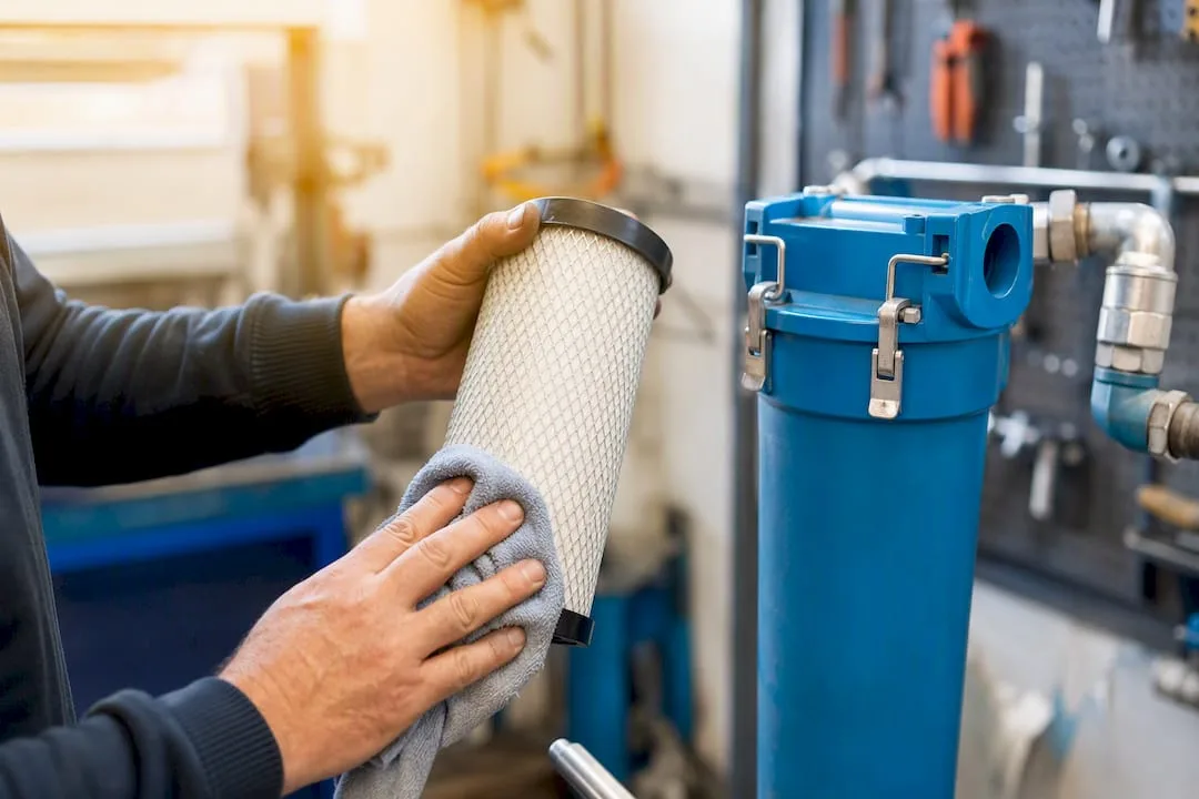
How to increase the energy efficiency of compressed air
Compressed air is often described in operation as a "hissing energy guzzler" – and rightly so, if nobody pays attention to how much air is lost through leaks or incorrectly set pressure. A basic energy audit takes one working cycle and measures three variables: total consumption in kWh per m³ of air, the share of leaks in total output, and pressure stability over time.
- Measure consumption with a flow meter at the compressor station, not by estimating from the nameplate output.
- Fix leaks as the first step – it tends to be the cheapest and fastest measure with an immediate effect.
- Consider a VSD compressor where the load fluctuates and the unit will run within an efficient range.
- Optimize the operating pressure to the actual needs of the machines, not to a "safety margin" of an extra bar.
That is a difference that is noticeably reflected in the annual electricity bill, especially in multi-shift operation.
Installation and operation checklist according to Kompresory-vzduchotechnika
The technicians at Kompresory-vzduchotechnika recommend the following minimum air treatment setup for a CNC line:
- dryer (refrigerant or adsorption, depending on the required dew point),
- multi-stage filtration with a condensate separator, coarse and final filter,
- automatic drain,
- Dew point sensor with alarm for continuous quality monitoring.
Procedure when planning or upgrading a system:
- Check the current air quality against the filtration programme according to ISO 8573.
- Review the list of tasks for technicians and plan maintenance intervals.
- Order a turnkey design, installation or energy audit directly from Kompresory-vzduchotechnika.
What I would address first when upgrading an air system
If I had to rank priorities, I would put air quality first, not compressor output. A faulty dew point will ruin precision faster than a missing bar of pressure. Only after drying and filtration are resolved does it make sense to calculate output and consider VSD. Measurement is always cheaper than guesswork, and regular dew point monitoring pays off more in the long run than a one-off investment in a larger compressor.
Where to order air treatment and service for CNC operation
Kompresory-vzduchotechnika offers direct access to the technologies discussed above, without the need to source a dryer, filtration and dew point sensor separately from three different suppliers. The catalogue includes compressed air treatment units up to 18 bar as well as a complete filtration programme according to ISO 8573, so you can select the dryer, filters and condensate separator according to the same purity class all at once.
For distributing air to CNC machines, the range also includes compressed air hoses in dimensions common for machine shop operation, including braided versions for higher thermal and mechanical load. If you are deciding on or replacing a compressor, the entire catalogue of piston and screw compressors also includes VSD and oil-free variants suitable for sensitive processes.
Kompresory-vzduchotechnika also provides expert consulting, turnkey solution design, installation and energy audits focused on measuring consumption and leaks. If you are unsure about the current state of your distribution system, request a non-binding consumption measurement proposal or a consultation on selecting a dryer and filtration directly from the Kompresory-vzduchotechnika team.
Frequently asked questions
What dew point is suitable for CNC machining?
The specific value depends on the purity class according to ISO 8573 and on the machine manufacturer's requirements, so it is verified by continuous measurement, not a one-time check.
Is a refrigeration dryer sufficient for CNC, or is an adsorption dryer necessary?
A refrigeration dryer will cover standard blow-off and pneumatic actuators, while an adsorption dryer is used where the process requires a significantly lower dew point, for example in precision machining or sensitive optics.
What size compressor do I need for a CNC line?
When is a compressor with variable speed drive (VSD) worthwhile?
How often should leaks in the compressed air distribution system be checked?
Regular checks using an ultrasonic detector or a pressure drop test outside of operating hours should be part of routine maintenance, ideally as part of a program offered by Kompresory-vzduchotechnika.
Recommended
- Compressed air storage options: a guide for technicians - Kompresory-Vzduchotechnika.cz
- List of tasks for compressed air: a guide for technicians - Kompresory-Vzduchotechnika.cz
- The importance of compressed air automation in industry - Kompresory-Vzduchotechnika.cz
- Compressed air treatment units up to 18 bar

What material to choose for air distribution in a company or workshop
We have merged this article with a more detailed and more up-to-date guide on the same topic. Continue here: A guide to industrial air distribution: efficiency of operation.

Pressure vessels: Czech laws and operator obligations in 2026
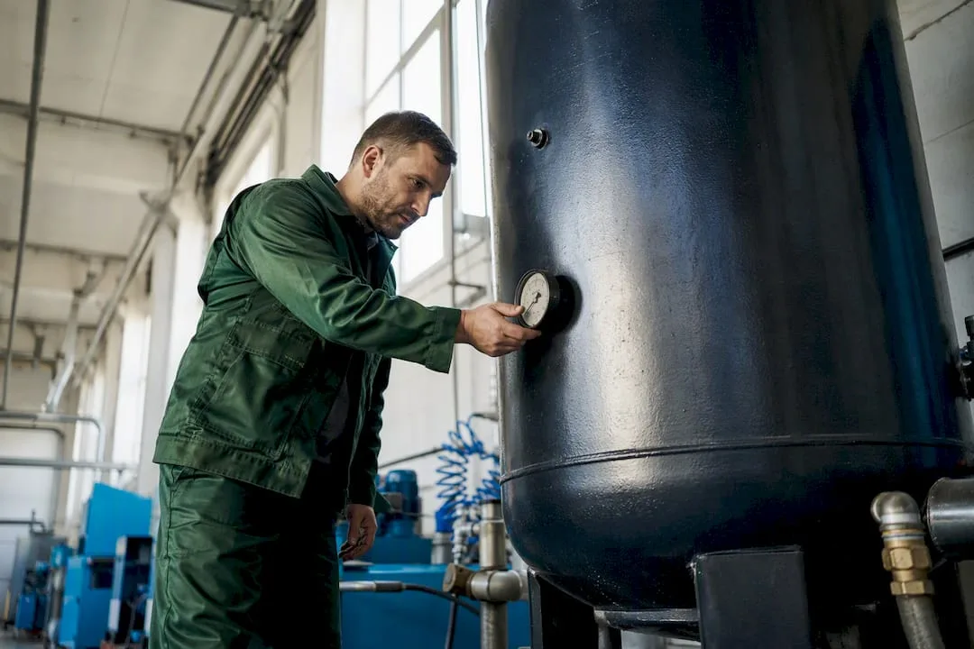
In the Czech Republic a pressure vessel becomes a reserved pressure device the moment the maximum working pressure (PS) exceeds 0.5 bar. This limit is set by Czech Government Regulation No. 192/2022 Sb., and as soon as the vessel exceeds it, a whole range of duties falls on the operator.
They must have a local operating procedure drawn up, keep an inspection plan and ensure that the equipment is operated by professionally competent persons. Czech Act No. 250/2021 Sb. clearly transfers responsibility for operating safety to the operator, not to the manufacturer or the inspection engineer.
The specific intervals can be found in Annex No. 4 to Government Regulation No. 192/2022 Sb. and in the technical standard ČSN 69 0012:
- Initial inspection before commissioning, first operational check within 14 days.
- Operational inspections are normally carried out annually, with longer inspection intervals for LPG and refrigeration equipment.
- Internal inspections are carried out according to the applicable rules at longer intervals.
- The pressure test is usually carried out at longer time intervals set by the relevant standards and decrees.
As regards placing simple pressure vessels on the market, the product PS·V is decisive. If it exceeds 50 bar.L, the vessel must undergo conformity assessment under Government Regulation No. 119/2016 Sb., including EU type-examination in the so-called module B.
Key findings
The operator of a pressure vessel with PS above 0.5 bar bears full responsibility for operating safety and must manage inspections according to the actual operating conditions, not merely according to the statutory maximum.
| Point | Details |
|---|---|
| Classification of the equipment | A vessel with PS > 0.5 bar is a reserved pressure device under Czech GR 192/2022 Sb. |
| Key documents | Ensure a local operating procedure and an inspection plan before commissioning. |
| Inspection intervals | Operational inspection annually, internal inspection after 5 years, pressure test after 9 to 10 years. |
| Conformity assessment | Vessels with a product PS·V above 50 bar.L require conformity assessment under Czech GR 119/2016 Sb. |
| Certified supply | Kompresory-vzduchotechnika supplies air receivers according to ČSN EN 286-1 including installation and service. |
Contents
- Why the inspection engineer's stamp is not enough
- How Kompresory-vzduchotechnika helps you with pressure vessels
- Where to check the regulations and technical standards
- Frequently asked questions
Why the inspection engineer's stamp is not enough
The legislation has shifted responsibility for safety unequivocally onto the operator. In practice this means that the inspection plan must not merely copy the statutory maximum intervals, but has to be based on the manufacturer's documentation and on the actual operating conditions of the particular vessel.
A vessel working with an aggressive medium or in a dusty operation needs more frequent checks than the statutory maximum permits. This includes demonstrable training of the operating staff and ongoing communication with the inspection engineer, not just a one-off contact once a year.
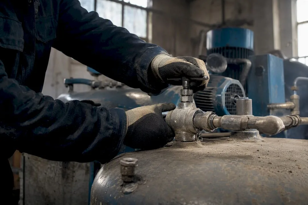
How Kompresory-vzduchotechnika helps you with pressure vessels
Supplying a certified vessel is only the first step. Kompresory-vzduchotechnika offers pressure vessels and air receivers with a volume of 725 litres manufactured in compliance with ČSN EN 286-1, complemented by installation, drawing up the local operating procedure and follow-up service.
That is the difference from buying a “bare” vessel without support. Our technicians help set up the inspection plan according to the real load of the operation, not just according to table intervals, and they also arrange the connection via pipes for compressed air distribution if you are building a compressor room from scratch. If you are dealing with the purchase of a new vessel or the inspection of an existing air receiver, contact our technical department and arrange a consultation directly on site.
Where to check the regulations and technical standards
The full wording of the main Czech regulations can be found on the portals ZákonyProLidi.cz or ČeskéZákony.cz. We recommend starting with Annex No. 4 to Government Regulation No. 192/2022 Sb., because it contains the specific inspection intervals.
For the classification of the equipment and the operator's duties, Government Regulation No. 192/2022 Sb. is the key one; for placing simple pressure vessels on the market it is Government Regulation No. 119/2016 Sb., and for responsibility for occupational safety it is Act No. 250/2021 Sb. Conformity assessment in general is governed by Act No. 90/2016 Sb. All the regulations named here are Czech law. Technical practice is complemented by the standards ČSN 69 0012 and ČSN EN 286-1.
Practical steps for maintenance and documentation can be found in the guide to caring for a compressor vessel and in the checklist of safety rules for compressor operation.
Frequently asked questions
When is a pressure vessel a reserved device?
As soon as the maximum working pressure (PS) exceeds 0.5 bar, under Czech Government Regulation No. 192/2022 Sb. it is a reserved pressure device with a full inspection obligation.
How often must a pressure vessel be inspected?
The operational inspection is done once a year, the internal inspection once in five years and the pressure test approximately once in 9 to 10 years according to Annex No. 4 to GR 192/2022 Sb.
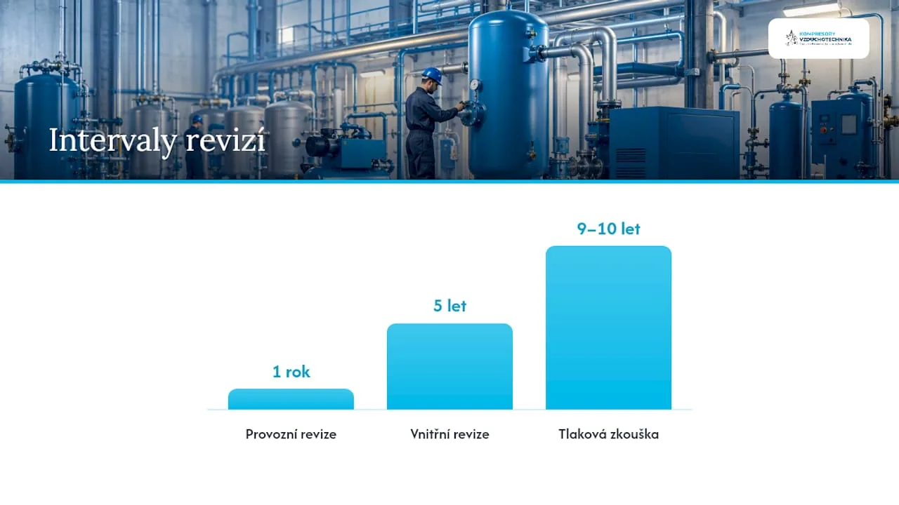
Who is responsible for the operating safety of the vessel?
Responsibility lies with the operator, who must ensure the local operating procedure, the inspection plan and professionally competent operating staff under Czech Act No. 250/2021 Sb.
When must a simple pressure vessel undergo conformity assessment?
If the product PS·V exceeds 50 bar.L, the vessel requires conformity assessment under Czech Government Regulation No. 119/2016 Sb., including EU type-examination.
Where to buy a pressure vessel that complies with the standards?
Kompresory-vzduchotechnika supplies air receivers in compliance with ČSN EN 286-1 including installation, operating documentation and service.
Recommended

Remote Compressor Monitoring: Deployment Plan for Technicians
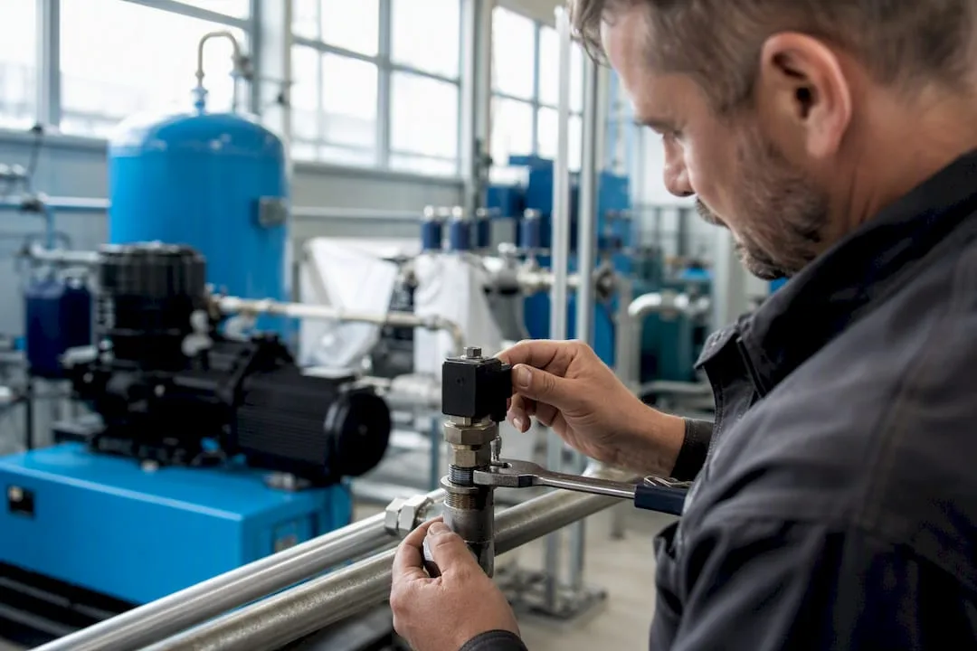
Remote compressor monitoring ensures continuous measurement of pressure, flow, temperature and vibration, and sends warnings before a failure occurs. Industry estimates suggest that typical operation loses up to approximately one-fifth of compressed air due to leaks. Systems built on protocols such as OPC UA or Modbus detect this loss within days, not months. Kompresory-vzduchotechnika.cz offers local support in designing and installing such a solution.
The main benefits can be summarized in three points:
- lower energy consumption thanks to early detection of leaks and overloads,
- fewer emergency repairs, because deviations are addressed before they develop into a failure,
- maintenance planned according to the actual condition of the machine, not according to a calendar.
Professional tip: Before you start selecting sensors, measure the compressor's current weekly energy consumption. Without a baseline value, you won't know whether monitoring actually saved anything.
Key findings
Remote monitoring only works when it combines the right metrics, reliable connectivity and a clearly defined pilot step before full deployment.
| Point | Details |
|---|---|
| Main benefit | Combining pressure, flow and vibration reveals a leak or failure before it causes a shutdown. |
| Leak losses | Expert estimates indicate a loss of up to 20% of compressed air due to unaddressed leaks. |
| Protocol selection | Modbus TCP and OPC UA are suitable for wired networks, NB‑IoT and LoRaWAN for remote locations. |
| Pilot before scaling | Verification on 1 to 3 machines over a period of 4 to 6 weeks will show the real return on investment. |
| Supplier selection | Kompresory-vzduchotechnika.cz offers audit, installation, integration, and continuous service as a single package. |
Contents
- What exactly remote compressor monitoring means
- Which variables to monitor and what thresholds to set
- What components make up the monitoring system
- Which protocol and connection to choose for your operation
- How to deploy remote monitoring step by step
- How much remote monitoring costs and when it pays off
- How to secure data between the operational and IT network
- What to consider when choosing a remote monitoring supplier
- Technician Zdeněk's note: what is most often underestimated in practice
- How Kompresory-vzduchotechnika.cz can help you with deployment
- Recommended resources and further reading
- Frequently asked questions
What exactly remote compressor monitoring means
Remote compressor monitoring is a system that measures the machine's operating parameters using sensors, transmits the data via a gateway to a cloud-based or local platform, and evaluates it against set limits. A control unit such as the Elektronikon Nano can monitor pressure, temperature, and operating modes in real time and make them accessible via an application such as SMARTLINK, from anywhere the technician has internet access.
The system works in two modes:
- active monitoring – the technician reviews the data themselves and looks for deviations,
- passive monitoring – the system automatically sends an alert only when a value exceeds the threshold.
Deployment is divided into a cloud solution, where data travels to a remote server, and a local network (LAN), which integrates data directly into SCADA via Modbus TCP, OPC UA, or Profinet. The choice depends on whether the company prefers remote access from multiple locations, or a closed network with full control over the data.
Which variables to monitor and what thresholds to set
Monitoring a single variable on its own does not reveal much. The real diagnostic value comes from combining pressure, flow, and vibration, as this shows whether the problem stems from a leak, bearing wear, or compressor overload.
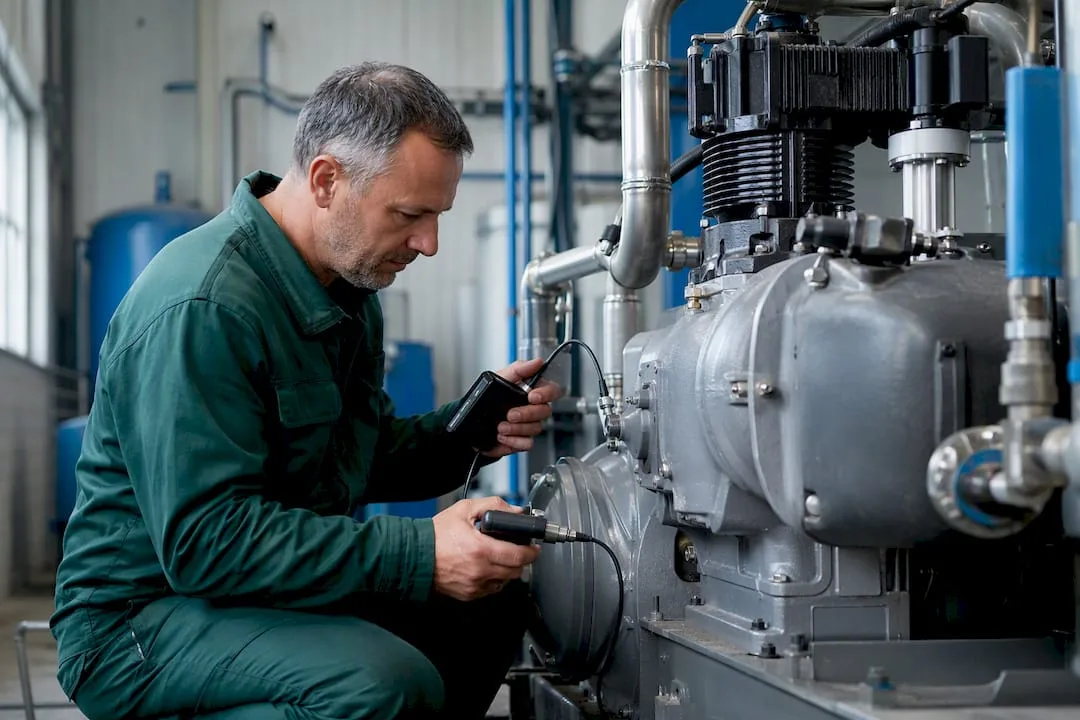
| Variable | Why monitor it | Sensor type | Example threshold value |
|---|---|---|---|
| Pressure | Reveals leaks and undersized piping | Piezoelectric pressure sensor | A drop of more than 0.5 bar compared to the operating pressure |
| Flow rate | Shows actual air consumption vs. machine output | Flow meter (thermal or vortex) | Deviation above planned consumption |
| Temperature | Signals overheating of the oil or motor | Thermocouple / resistance sensor | Above the operating temperature for oil-lubricated compressors |
| Vibration | Reveals bearing wear and imbalance | Accelerometer | Above the vibration value typical for the given machine |
| Motor current | Indicates mechanical overload | Current transformer | Deviation above the rated value |
| Operating hours | Service interval planning | Counter in the control unit | Approaching manufacturer's service interval |
| Air leaks | Direct energy loss | Acoustic leak detector | Estimated loss of over 5% of total output |
The estimate that leaks account for a loss of up to approximately one-fifth of compressed air applies to the entire range of industrial piping systems, not just the compressor itself. A persistent deviation lasting longer than one shift is no longer noise, but a signal for intervention. More on how to evaluate vibrations in practice is described in the guide to monitoring compressor vibrations.
Professional tip: Combine pressure, flow, and vibration in a single graph. A pressure drop without a flow drop usually indicates a leak, while a drop in both accompanied by increasing vibration indicates a mechanical fault.
What components make up a monitoring system
The system consists of four layers, and if one is missing, the entire solution loses its purpose.
- Sensors – measure pressure, temperature, vibration, and current directly on the machine; when selecting them, IP65 or higher protection rating, accuracy, and vibration resistance are decisive factors.
- Gateway – aggregates data from sensors and converts it from industrial protocols into a format readable by the cloud or SCADA.
- Cloud or software platform – stores history, generates overviews, and triggers alarms; a system such as SMARTLINK can log data at intervals of just a few minutes, giving the technician a fast reaction time.
- Notification module – sends alerts by e-mail, SMS, or to an app as soon as a value exceeds the set threshold.
Above these four layers sits a central control unit, the so-called optimizer, which distributes the load among multiple compressors according to current demand.
Evenly distributing operating hours among the machines extends the lifespan of the entire compressor fleet and at the same time reduces energy consumption, as the system shuts down machines that are not needed at a given moment.
The principle of central control and its practical benefits are discussed in the article on parallel compressor control.
Which protocol and connection to choose for your operation
The choice of connectivity determines the reliability of the entire system, not just the data transfer speed.
- Modbus TCP – a standard for integration into an existing SCADA system, low latency, but limited security without additional encryption.
- OPC UA – a modern replacement for Modbus with a built-in security layer, suitable for larger operations with multiple systems.
- MQTT – a lightweight protocol ideal for cloud transfers from remote locations with limited bandwidth.
- NB-IoT and LoRaWAN – wireless technologies for locations without cable infrastructure, such as outdoor compressor stations.
For a hall with dozens of measuring points and an existing SCADA system, Modbus TCP or OPC UA over a wired network makes sense. For a remote location where cable routing is costly, NB-IoT or LoRaWAN is worthwhile. For critical operations, we recommend a backed-up network path and edge computing, which filters noise directly at the source before the data travels to the cloud.
How to deploy remote monitoring step by step
It makes sense to divide the deployment into five phases that follow one another, each verifying whether continuing makes economic sense.
- Compressed air system audit – map the existing compressors, piping, and known weak points.
- Selection of metrics and sensors – depending on the type of operation, you determine which variables from the previous table have priority.
- Pilot deployment on 1 to 3 machines – verifies the functionality of sensors, data transfer, and notifications in real operation.
- Evaluation of key performance indicators (KPI) – you compare energy consumption, number of failures, and downtime duration before and after deployment.
- Scaling to the entire operation – once the benefits are confirmed, you expand the system to the remaining machines.
Before starting the pilot, check this checklist:
- calibration of all sensors against a reference gauge,
- synchronization of timestamps between sensors and the platform,
- testing notifications on a simulated deviation,
- backup of the configuration before going live.
It makes sense to run the pilot for at least four to six weeks in order to cover normal operational fluctuations as well as at least one service intervention. A shorter period usually does not provide enough data for a reliable comparison. The procedure after installation, including bleeding the system, is described in the compressor bleeding guide.
How much remote monitoring costs and when it pays off

The price is affected by five items: sensors, gateway, installation, software platform licenses, and data connectivity. A service contract for regular inspection and calibration is often added to this.
A simple formula for estimating return on investment looks like this:
- ROI = (energy savings + reduced repair costs − solution costs) / solution costs
If monitoring detects and fixes a leak that cost the company approximately one fifth of the compressor's output, the energy savings alone will often cover part of the investment within one year. Add to that a lower number of emergency service call-outs thanks to planned maintenance based on the actual condition of the machine, not on a fixed schedule, and the payback period shortens even further. You can find specific savings calculations for specific compressor types in the energy savings guide.
How to secure data between the operational and IT networks
The connection between the operational network (OT) and IT infrastructure is the most common weak point of the entire deployment if it is underestimated from the start.
- Network segmentation – compressor monitoring has its own VLAN separated from the rest of the production network.
- Transmission encryption – a VPN tunnel or TLS encryption between the gateway and the cloud platform.
- Access rights management – each technician has their own login credentials, not a shared account.
- Regular firmware updates – gateways and sensors need patches just like computers do.
This includes clear rules for the data itself:
- the historical data retention period meets the needs of service, typically 12 to 24 months,
- data ownership clearly remains with the operator, not with the software vendor,
- service teams have read-only access, not administrator rights, unless necessary,
- audit logs record every intervention in the alarm configuration.
What to look for when choosing a remote monitoring provider
The provider determines whether the system actually works after installation, or just collects data that nobody evaluates.
- Check whether the provider offers local service support, not just hardware sales.
- Find out which industrial protocols the provider commonly integrates and whether they have reference installations of a similar scale.
- Require a clearly defined SLA for service interventions, including response time in the event of a failure.
- Ask about spare parts availability and their delivery time.
Kompresory-vzduchotechnika.cz covers these requirements with a complete offering ranging from turnkey solution design through installation to energy audits and round-the-clock service.
A good provider will propose a pilot verification on one or two machines before offering a quote, rather than immediately supplying sensors for the entire operation. If they don't offer this option, it's more about selling hardware than providing a real solution.
When requesting a quote, ask specifically: how long calibration takes after installation, what format the output data is in, and who handles service when a sensor stops communicating.
Note from technician Zdeněk: what is most often underestimated in practice
The most common mistake when installing sensors is placing them too close to a vibration source, which distorts the measured values and leads to false alarms. Never calibrate right after starting the machine, but only after it has warmed up to operating temperature. One pilot on two machines once showed me a leak that the operator had overlooked for months, because no pressure gauge on the panel displayed it.
How Kompresory-vzduchotechnika.cz will help you with deployment
Kompresory-vzduchotechnika.cz approaches remote monitoring differently than a supplier who just ships a box of sensors. We offer a complete process from an audit of the existing compressed air system through sensor and gateway design, installation, integration into your SCADA network, all the way to an energy audit that calculates the real payback before an investment decision is made.
Standard cooperation begins with a non-binding contact, followed by a technical audit of the operation, design of a pilot solution on one to three machines, and only after its evaluation, delivery for the entire operation. Thanks to our local service network, we handle sensor and gateway failures without weeks of waiting for a spare part.
If you want to find out where your operation is losing the most compressed air, take a look at our pneumatics and hydraulics offer and request a non-binding consultation on the energy audit of your compressor fleet.
Recommended sources and further reading
- Compressor diagnostics for efficient operation – expands on the topic of rapid fault identification.
- Monitoring compressor vibrations – a practical guide from technician Zdeněk.
- Definition of the compressor duty cycle – helps with planning the pilot.
Frequently Asked Questions
What is remote compressor monitoring?
It is a system of sensors, a gateway and a software platform that continuously monitors the compressor's pressure, temperature, vibrations and other variables and alerts you to deviations via the internet.
Which protocol is the most reliable for monitoring?
It depends on the operation: OPC UA and Modbus TCP are suitable for wired networks and SCADA integration, while NB‑IoT and LoRaWAN are suitable for remote locations without wired infrastructure.
How long does a pilot monitoring deployment take?
A pilot phase on 1 to 3 machines typically lasts 4 to 6 weeks, which covers normal operating fluctuations as well as at least one service intervention.
How much can be saved by detecting leaks?
Industry estimates indicate that unaddressed leaks cost a facility up to approximately one-fifth of the compressed air produced, so their early detection often translates into savings already within the first year.
Where to request installation and servicing of the system?
Kompresory-vzduchotechnika.cz provides the audit, design, installation and continuous servicing of remote monitoring, including an energy audit of your facility.
Recommended

Screw Compressor Overheating: Quick Action and Prevention
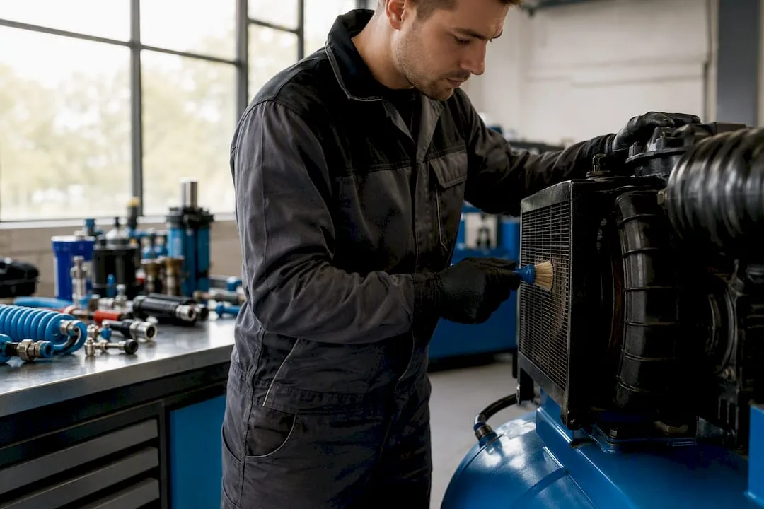
The most common causes of screw compressor overheating are four: a clogged cooler, degraded or insufficient oil, fan failure, and poor compressor room ventilation. A fifth, less obvious culprit is overload beyond the designed output.
As soon as the control unit reports a high temperature, do the following:
- relieve the load or switch to idle,
- check the oil level and colour,
- remove anything obstructing airflow around the cooler.
If the temperature does not drop within a few minutes after these steps, shut down the unit and call service. The risk of damage to the screw block and bearings increases with every minute of operation above the limit temperature.
Key takeaways
Screw compressor overheating is most often caused by a combination of a clogged cooler, degraded oil, and insufficient ventilation, which can largely be detected through regular measurement and cleaning.
| Point | Details |
|---|---|
| Main causes | A clogged cooler, poor oil, fan failure, and insufficient compressor room ventilation account for most cases of overheating. |
| Immediate response | Relieve the load, check the oil, and remove any obstructions to airflow, then monitor whether the temperature decreases. |
| Threshold values | Normal oil temperature is 60–85°C, with safety shutdown typically set at around 95–105°C. |
| Diagnostics before repair | Multi-parameter diagnostics (vibration, thermal mapping, oil analysis) reveal internal faults sooner than visual inspection. |
| Prevention works | Regular oil changes, cooler cleaning, and monitoring of operating data significantly reduce the risk of unplanned downtime. |
| Expert support | Kompresory-vzduchotechnika offers diagnostics, oil analysis, monitoring, and supply of spare parts to address recurring overheating issues. |
Contents
- Immediate checklist when overheating is detected
- Main technical causes of overheating by subsystem
- How to diagnose compressor overheating step by step
- Preventive maintenance that actually reduces the risk of overheating
- When to call service and how to safely wait for intervention
- Frequently asked questions
Immediate checklist when overheating is detected
Before touching anything, disconnect the compressor from the power supply and let it cool down. Hot piping and oil can cause burns even after the motor has been switched off.
Proceed in this order:
- Record the reported alarms and the time they occurred.
- Check the oil level and its color (dark or cloudy oil indicates oxidation).
- Verify that the fan is turning and that the belt is not slipping or broken.
- Inspect the cooler fins for dust or grease buildup.
- Check the temperature and air flow in the compressor room.
During the check, record four values: oil discharge temperature, block housing temperature, oil pressure, and number of operating hours.
Professional tip: Normal oil discharge temperature for most screw compressors ranges between 60 and 85 °C. The factory setting for safety shutdown is usually around 95 to 105 °C – if the unit reports this threshold repeatedly, it is not a coincidence but a systemic fault.

If the measured values exceed the normal range even after cleaning the cooler and topping up the oil, the problem likely lies within the oil circuit or the thermostatic valve.
Main technical causes of overheating by subsystem
Overheating of a screw compressor rarely has a single cause. It is usually a combination of minor deficiencies that add up to one major problem. Breaking it down by subsystem helps identify the culprit faster than a general inspection.
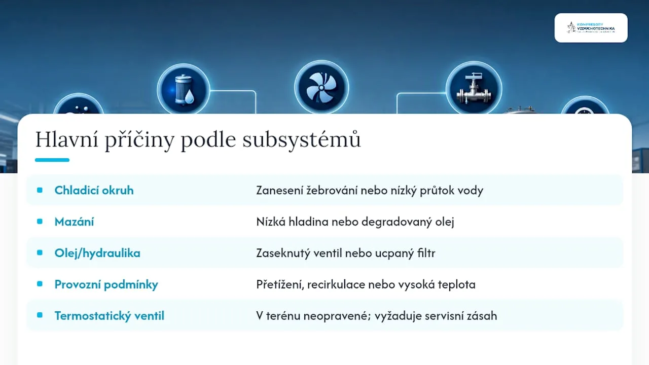
Cooling circuit. Clogged cooler fins block air flow and reduce heat transfer efficiency. For air-cooled units, a layer of dust and grease just a few millimeters thick is enough to raise the temperature by tens of degrees. For water-cooled compressors, the same effect is caused by low cooling water flow or deposits in the water circuit. Typical symptom: the temperature rises gradually, even under normal load.
Lubrication. Low oil level, oxidized oil, or incorrect viscosity increase friction between the rotors and bearings. Degraded oil loses both its lubricating and cooling properties at the same time, because in a screw compressor, the oil does not only lubricate but also dissipates a significant portion of the heat from the screw block. The result is increasing energy consumption and accelerated wear.
Oil and hydraulic components. A stuck thermostatic valve is a deceptive fault because it outwardly looks like a cooling problem. The oil circulates only through a short bypass and does not use the main cooler at all. You can recognize it with a simple test: the piping leading to the cooler remains cold to the touch, even though the control unit reports overheating. A clogged oil filter or a worn oil separator leads to a similar effect, and in addition, oil may enter the discharge air.
Operating conditions. Overloading beyond the designed output, recirculation of hot exhaust air back into the intake, and ambient temperature above the manufacturer's limit can overheat even a technically sound compressor. Improper ventilation of the compressor room is among the causes most often underestimated by field technicians.
A stuck thermostatic valve or a worn oil separator cannot be repaired in the field. That is where prevention ends and service intervention begins.
How to diagnose compressor overheating step by step
Diagnostics without measurement is just guesswork. Many technicians recommend first ruling out external factors – ventilation, ambient temperature, cooler cleanliness – and only then looking for an internal fault, such as a stuck thermostatic valve or a blocked pipe.
Basic diagnostic equipment:
- a contact or non-contact thermometer, or possibly a thermal camera for quickly mapping hot spots,
- a pressure gauge for measuring oil pressure and differential pressure across the separator,
- an oil sampling kit,
- an ultrasonic probe for checking bearings,
- a vibration analyzer for monitoring the condition of the screw block.
Multiparametric diagnostics combining vibration, thermal mapping, oil analysis, and ultrasound allows quantitative evaluation of the compressor's condition and prediction of faults before they become visible. A study on screw compressor diagnostics describes the application of this combination of methods on several units with a clear benefit for fault prediction.
What specifically to measure and how to read the results:
- Oil outlet temperature – normally 60 to 85 °C; values consistently above 90 °C indicate a problem with cooling or lubrication.
- Block housing temperature – compare with values from previous measurements, not just a one-time limit.
- Differential pressure across the separator – an increasing value indicates a clogged separator.
- Motor voltage and current – deviations may indicate mechanical overload.
If the temperature does not drop after cleaning the cooler and topping up the oil, send an oil sample for laboratory analysis. The result will show the degree of oxidation, the content of metal particles from wear, and any contamination, which provides a more accurate basis for a service decision than visual inspection alone.
Preventive maintenance that actually reduces the risk of overheating
Regular maintenance – oil and filter changes, cooler cleaning, and monitoring of operating parameters – is among the most effective ways to reduce the risk of overheating and unplanned downtime. However, this only works if the schedule has a clear structure.
Approximate schedule of activities:
- Daily – checking the display, alarms, and oil level.
- Weekly – visual inspection of the cooler and the area around the fan.
- Monthly – cleaning the cooler with compressed air and checking belt tension.
- Quarterly – checking the condition of the oil filter and separator.
- Annually – oil change according to the manufacturer's recommendations and sampling for laboratory analysis.
Practical measures with the greatest impact:
- Cleaning air-cooled coolers by blowing against the direction of the cooling air flow, at a pressure of approximately 0.4 MPa – the opposite direction would push dirt deeper into the fins instead of removing it.
- Oil and filter changes according to actual operating hours, not the calendar.
- Check the area behind the fan and inside the enclosure, which field technicians often overlook, even though it significantly affects heat dissipation.
Where it makes sense to invest in modernization: fan speed control based on actual temperature, improved ventilation of the compressor room, additional hot air extraction, or remote monitoring of key parameters. For a more detailed overview of benefits and technical parameters, see the overview of benefits of screw compressors for industry.
Professional tip: Choose oil viscosity based on the actual operating temperature in the compressor room, not according to the recommendations in a manual from a different climate zone. In hot and dusty operations, it is worth shortening the oil change interval compared to the manufacturer's recommendation.
When to call service and how to safely wait for intervention
Some signals indicate that the situation goes beyond routine on-site maintenance. These include repeated automatic shutdowns due to overheating, elevated levels of metal particles in oil analysis, or unusual vibrations and noise indicating rotor or bearing wear.
Before the service technician arrives:
- Shut down the compressor safely – do not disconnect it under load; let it run idle for 5 to 10 minutes and only then stop it.
- Secure the location against unauthorized manipulation and mark the unit as out of service.
- Prepare a record of alarms, measured values, and maintenance history.
For the service team, this means faster diagnostics:
- record of operating hours since the last oil change,
- oil sample, if one was taken,
- description of the circumstances under which the overheating occurred.
Predictive maintenance as the next step
Modern control units today commonly collect temperatures and generate service signals in real time, enabling a shift from reactive repairs to predictive maintenance. Monitor three signals: oil outlet temperature trend, oil quality, and hours under load. For a pilot deployment, a basic sensor set and data collection over three to six months is sufficient before you set precise alarm thresholds.
What I take away from my own experience
Companies that keep a simple paper or digital checklist by the control panel deal with overheating significantly less often than those that rely solely on the operator's memory. I recommend introducing regular operator training to recognize early warning signs and replacing parts according to operating hours, not only after a failure occurs. Schedule preventive service at the point when measured values start to slowly rise, not only once the alarm sounds.
How Kompresory-vzduchotechnika can help you
Repeated overheating of a screw compressor is rarely solved by a single repair. Kompresory-vzduchotechnika offers a combination that a standalone service intervention cannot: on-site expert diagnostics, oil analysis, supply of original filters and spare parts, and installation of operating parameter monitoring, all under one roof.
If overheating keeps recurring on your unit even after basic maintenance, we offer consultation and diagnostics directly at your site, so you can identify the real cause before the screw block is damaged. A full overview of our service and consulting offerings can be found on the services page. If the problem stems from a worn-out separator or your unit is beyond economical repair, take a look at the range of SCR screw compressors and see how modernization affects the energy consumption of the operation. Get in touch via the contact form to arrange a diagnostic appointment.
Frequently asked questions
What is the normal operating temperature of a screw compressor?
Oil outlet temperature in most screw compressors ranges between 60 and 85 °C; the safety shutdown is typically factory-set to around 95 to 105 °C.
What should you do first when the compressor overheats?
Relieve the load, check the oil level and colour, and remove anything obstructing airflow around the cooler, then monitor whether the temperature drops.
How do I recognise a stuck thermostatic valve?
The piping leading to the main cooler remains cold to the touch even though the control unit reports a high temperature, because the oil is circulating only in a short bypass.
How often should the cooler of a screw compressor be cleaned?
Perform a visual inspection weekly, and carry out thorough cleaning with compressed air against the direction of cooling air flow at least once a month, or more often depending on the dustiness of the operation.
When is it necessary to call in service instead of carrying out your own repair?
Call service in case of repeated automatic shutdowns, elevated levels of metal particles in oil analysis, or unusual vibrations indicating wear of bearings or the rotor. In such cases, Kompresory-vzduchotechnika offers diagnostics directly on site.
Recommended


Compressor trips the circuit breaker: main causes and how to fix it
The most common cause is motor startup under pressure, when a malfunctioning pressure relief valve forces the motor to draw many times higher current than the circuit breaker is rated for. The second most common cause is an incorrectly selected circuit breaker characteristic. Type B is often unsuitable for compressors because it trips already at a short current surge, which is common with these motors.
Before you start disassembling anything, check these three things:
- Pressure relief valve – releases pressure from the cylinder head after stopping, so the next start isn't "under load".
- Circuit breaker type – check the letter on the circuit breaker in the distribution panel (B, C, or D).
- Motor mechanics – listen for unusual sounds during startup, difficult piston or bearing movement.
The first step is always to safely disconnect from power supply and visually inspect the pressure relief valve, as this is where the cheapest and fastest fix is usually found.
Key findings
The compressor most often trips the circuit breaker due to startup under pressure caused by a malfunctioning pressure relief valve combined with an unsuitable circuit breaker characteristic.
| Point | Details |
|---|---|
| Check the valve first | The pressure relief valve on the pressure switch is the most common and cheapest cause of a hard start. |
| Starting current is key | A motor can draw 10 to 12 times its rated current at startup under pressure. |
| Choose the correct characteristic | A type C or D circuit breaker withstands a compressor's current surge better than a standard type B. |
| Measure before replacing parts | An ammeter and megohmmeter distinguish an electrical fault from mechanical seizing. |
| Service for persistent faults | Kompresory-vzduchotechnika offers diagnostics, valve repair, and softstarter installation with an on-site technician. |
Useful resources and further reading
For a deeper understanding of the topic, we recommend:
- How a piston compressor works – where the unloading and check valve are located in the design.
- Compressor bleeding procedure – a step-by-step guide for technicians.
- Safety rules for working with a compressor – before you start the diagnostics yourself.
Contents
- Quick checks you can do right away without tools
- Main technical causes of the circuit breaker tripping the compressor
- Diagnostics: what to measure and how to read the results
- Practical solutions: from quick fixes to permanent remedies
- Prevention: how to avoid repeated tripping
- When it's time to call service or an electrician
- Service, parts, and advice from Kompresory-vzduchotechnika
- Frequently Asked Questions
Quick checks you can do right away without tools
Before reaching for a multimeter, switch off the main power supply and make sure the compressor is de-energized. Working in a live electrical panel without professional qualification is an unnecessary risk that is easy to avoid.
Follow this simple sequence:
- Listen to the start: a sharp “braking” sound of the motor during start-up indicates a hard start under pressure.
- Check whether air escapes from the unloader valve at the pressure switch after the compressor switches off (it should take a few seconds).
- Look at the letter on the circuit breaker in the distribution board. Type B is unsuitable for most compressors.
- Note whether the circuit breaker trips every time or only occasionally, and at what time of day.
Professional tip: If the circuit breaker doesn't trip on the first morning start but trips on a subsequent start later in the day, the problem is almost certainly not in the electric motor. It is a typical sign of a malfunctioning unloader valve or a leaking check valve, which leaves pressure in the cylinder between individual starts.
Repeated “circuit breaker tripping” is actually often a mechanical problem disguised as an electrical fault. Users focus on the circuit breaker, when in fact all that's needed is to clean or replace the small valve in the pressure switch.
For a more detailed understanding of how the internal mechanics of the machine work, it is worth reading through the working principle of a piston compressor, which shows exactly where the unloader valve and check valve are located.
The main technical causes of the circuit breaker tripping the compressor
The most likely cause is back pressure during start-up. When the unloader valve fails to release pressure from the cylinder head, the motor has to start against full compression. This dramatically increases both the starting torque and the current needed to turn the shaft at all.
Starting current is the key figure in the whole equation. A typical electric motor draws approximately 5 to 8 times its rated current during start-up. However, if the compressor starts under pressure, the current can briefly spike up to 10 to 12 times the rated draw. A circuit breaker with a type B characteristic is designed to trip at just 3 to 5 times the rated current, so with a compressor, a fault is practically guaranteed at every start.
Other common electrical causes include:
- Loss of one phase in three-phase motors, where the remaining two phases overload the winding.
- Faulty starting capacitor in single-phase motors, which extends the start-up time and increases current draw.
- Voltage asymmetry between phases, which loads the motor unevenly.
Mechanical faults form the second group. A seized piston, worn bearings, or a damaged connecting rod increase mechanical resistance, which is immediately reflected in electrical current draw. Diagnosing a faulty compressor often relies precisely on a combination of sound, temperature, and measured current, because the fault is rarely purely structural in nature. Frequent cyclic switching also contributes to this, where the motor starts and stops at short intervals and does not have time to reach thermal stabilization.
Diagnostics: what to measure and how to read the results
Reliable diagnostics requires three basic tools: a clamp ammeter, a megohmmeter (megger), and a multimeter. A thermal camera is a useful addition, but it is not necessary.
- Measure the starting current with a clamp ammeter directly at start-up. A value above 10 times the rated current confirms a start under pressure.
- Check the insulation condition of the winding with a megohmmeter and compare the resistances between the individual phases. A significant difference between phases indicates damaged winding.
- Verify the voltage and phase symmetry with a multimeter on all three conductors, if it is a three-phase motor.
- Observe the behavior under pressure relief – if manually opening the relief valve at start-up visibly reduces the current, you have confirmed the cause.
Where to look for warning signs:
- High current draw without an apparent short circuit often indicates mechanical seizure, not an electrical fault.
- To confirm a mechanical problem, it is advisable to measure the current with the mechanical load disconnected, if the design allows it, and compare it with a normal start.
- Differing resistances between phases in the winding indicate an impending motor fault, even if it still “works”.
Always perform live measurements with insulated tools and in a dry environment. If you are not confident working with electrical equipment, leave this step to a technician.
Practical solutions: from a quick fix to a permanent remedy
The cheapest and most frequently effective repair is cleaning or replacing the unloader valve on the pressure switch. For single-phase motors, replacing the start capacitor is often just as effective, as it wears out even without visible symptoms.
How to approach the repair:
- First check and repair the pressure components – the unloader valve and the check valve.
- If the problem persists, check and, if necessary, replace the start capacitor on single-phase motors.
- Only after that should you address the protection, and possibly install a soft starter or variable speed drive (VSD).
- For larger motors with accessible winding terminals, consider switching to star/delta starting.
More permanent solutions include:
- Replacing the circuit breaker with a C characteristic, which can handle the short current surge typical of compressors; for heavier machines or very frequent starting, type D is more suitable.
- Installation of a soft starter or VSD, which controls the starting current gradually and protects both the motor and the electrical grid.
- Converting the start-up to star/delta, if the motor design allows it.
As a rough guide: replacing a capacitor costs a few hundred CZK and can be done within an hour. A soft starter or VSD represents an investment in the range of thousands to tens of thousands of CZK depending on motor power, including labor.
Professional tip: Always address the mechanics and pressure components before replacing the circuit breaker. A stronger circuit breaker without repairing the unloading valve only hides the problem and risks damaging the motor.

Prevention: how to avoid repeated tripping
Regular maintenance of the unloading valve and check valve is the cheapest safeguard against repeated circuit breaker tripping. Most manufacturers recommend inspection with every oil and filter change.
It also helps to:
- Choose the circuit breaker characteristic based on the motor's actual starting current, not on the rated power input.
- For compressors with frequent starting, consider soft start already at installation, not just as a reaction to a problem.
- Let the pressure drop gradually before shutdown and avoid repeated starts shortly after one another.
Professional tip: Monitor how long the compressor runs between individual cycles. If it switches on more often than the manufacturer specifies, this is cyclic operation, which shortens the lifespan of both the motor and the unloading valve.
When it's time to call a service technician or an electrician
If the breaker trips even after cleaning the unloader valve and checking the capacitor, it is likely an internal fault in the motor or compressor unit. A burning smell, smoke, or unusual mechanical noises are a signal to shut down the machine immediately.
- Persistent tripping even after basic checks.
- Suspected damage to the windings or bearings inside the compressor.
- An unclear electrical fault that you cannot measure safely.
Modifying the main circuit breaker in the distribution board without the consent of the grid operator or a revision technician is a risk that is not worth taking. Always entrust work on the motor under voltage to an electrician with the appropriate qualification.
Brief recommendation from a technician
On site, I always start by checking the unloader valve, as this is the most common culprit and the repair takes minutes. Only then do I measure the starting current and the insulation condition of the windings. This procedure saves the customer time and money on an unnecessary breaker replacement.
Service, parts and advice from Kompresory-vzduchotechnika
Kompresory-vzduchotechnika is an alternative to arranging a service call through a random electrician without knowledge of pneumatics. We handle compressors comprehensively, from pressure components to electrical protection, so you don't need to contact two different companies for one problem.
We offer on-site diagnostics, repair and cleaning of unloader valves, installation of softstarters, and supply of spare parts, including capacitors and components for air distribution systems. The exact diagnosis and price quote will always be prepared by a technician after measuring the actual values directly on your machine, not estimated over the phone. If you need to replace piping or supplement your compressed air distribution system, check out pipes for compressed air distribution or the entire range of pneumatics and hydraulics and order a service call directly through the website.
Frequently asked questions
How does a faulty circuit breaker manifest itself?
A faulty circuit breaker trips even without an apparent load, or conversely, does not react at all to a current surge that should disconnect it. If the breaker trips regularly only with the compressor while other appliances on the same circuit work without problems, the fault usually lies in the compressor itself, not in the breaker.
How to recognise a faulty compressor?
A faulty compressor shows itself through unusual noises on startup, increased current draw, overheating, or a drop in performance. A combination of hard starting and repeated circuit breaker tripping almost always points to a problem with the unloader valve or mechanical load on the motor.
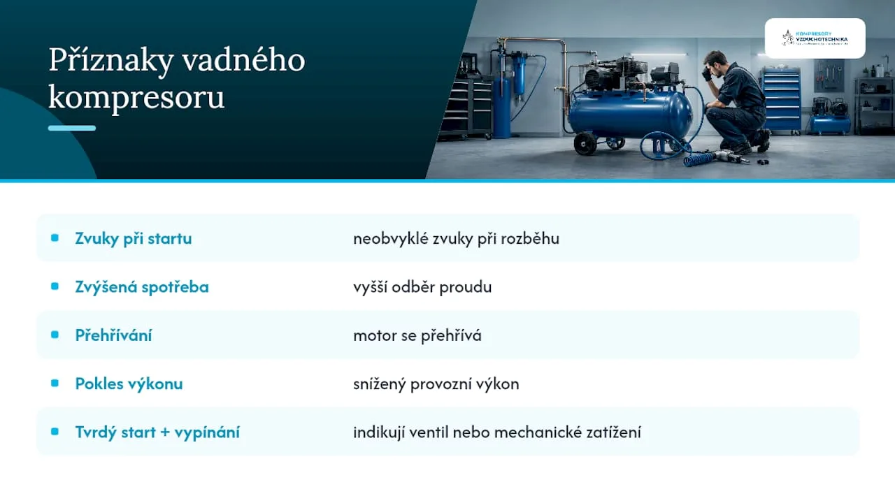
How to recognise a faulty air conditioning compressor?
In an air conditioning compressor, a fault is signalled by shaft leakage, mechanical noise, or contamination of the refrigeration circuit. In case of serious internal damage, it is usually necessary to flush the circuit or replace the compressor entirely.
How to reduce noise from a noisy compressor?
Noise can be reduced by placing the unit on rubber pads, acoustic insulation of the space, and regular inspection of loose parts and bearings. If the noise level has increased suddenly, it is often a mechanical fault that needs to be diagnosed first, not just muffled.
Which circuit breaker is most suitable for a compressor?
For most workshop compressors, characteristic C has proven effective; for heavier machines or very frequent starting, characteristic D is used. The choice depends on the actual motor starting current, which can be measured with a clamp ammeter directly during startup.
Recommended
- How to repair an air leak on a compressor: a 2026 guide - Kompresory-Vzduchotechnika.cz
- Avoid the most common mistakes when using compressors - Kompresory-Vzduchotechnika.cz
- Compressor bleeding procedure: a guide for technicians - Kompresory-Vzduchotechnika.cz
- The importance of compressor diagnostics for efficient operation - Kompresory-Vzduchotechnika.cz

Fire Safety of the Compressor Room: Procedure for the Operator
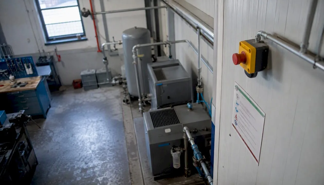
If you identify a risk during your own inspection, act immediately: stop operation in case of serious danger, isolate flammable liquids from the machine room, check the function of ventilation and safety valves, and order an updated fire safety design (PBŘ). Fire safety of the compressor room is not based on a single measure, but on a set of structural, technical, and organizational steps that must work together, and as soon as one part is missing, a fire brigade (HZS) inspection usually detects it first.
Before calling a PBŘ designer, check these six points yourself:
- Are flammable liquids (oils, cleaning agents) stored outside the compressor room?
- Does the emergency ventilation shutdown, operable both from inside the room and from outside, work?
- Are functional safety valves installed between the compressor and the first shut-off device?
- Does the classification and fire resistance of fire barriers (doors, dampers) correspond to the current operating condition?
- Is the condensate disposal system functional, with no oil leaking onto the floor?
- Do you have valid inspection reports for the electrical installation, pressure vessels, and fire extinguishers?
Professional tip: If you are not sure whether your existing PBŘ corresponds to the actual state of the technology, do not rely on guesswork. Changing the compressor output, adding a dryer, or modifying the piping can push the fire load beyond the scope of the original assessment, and this is exactly the type of discrepancy that the fire brigade (HZS) will detect first during an inspection.
Contents
- Requirements for building structures and division into fire compartments
- Technical measures in the compressor room: ventilation, fittings, electrics, condensate, and measurement
- Organisational measures and operating regime in the compressor room
- Fire safety design (PBŘ) and risk assessment: what it must contain
- Key standards and legal regulations you need to know
- Inspections, revisions and requirements for professional competence
- Practical checklist for operators: what to check today
- Recommendations from an operating supplier: a practical view of common mistakes
- How Kompresory-vzduchotechnika can help you
- Key conclusions for decision-making
- Useful resources and standards to check
- Frequently asked questions
Requirements for building structures and division into fire compartments
From a fire safety perspective, the compressor room is assessed as a separate or associated fire compartment, and this affects the required fire resistance of the surrounding walls, ceiling and doors. The methodological guideline for the design and assessment of fire safety design classifies the compressor room among the operations where the division into fire compartments (PÚ) is assessed individually, depending on the quantity of flammable substances, the output of the installed equipment, and its location within the building.

A typical value you will encounter in practice is structural resistance at the F30 level, i.e. medium-term resistance of walls and ceilings. However, this is really only an indicative value. The specific requirement is always determined by the risk assessment in the Fire Safety Design Documentation (PBŘ), and for more powerful machines with oil injection, separate fire protection rooms with stricter separation and a more resistant floor structure are often recommended in practice, because the risk of fire spreading through oil residues is higher.
Fire closures, i.e. doors, dampers and shaft closures, must have resistance corresponding to the class of the given fire compartment, and their function (self-closing, tightness, possibly status signalling) is documented separately.
| Structural element | What is assessed |
|---|---|
| Walls and ceilings of the fire compartment | Fire resistance class according to risk (often indicatively F30) |
| Doors and dampers | Resistance, self-closing mechanism, tightness |
| Shafts and penetrations | Sealing, fire protection collars, inspection of installation penetrations |
| Floor | Non-combustible, oil-resistant surface for machines with higher power |
The documentation that the Fire Safety Report must include for this part comprises:
- Calculation of fire load and classification into a fire hazard category.
- Justification of the size and boundaries of the fire compartment.
- Specification of the type and resistance rating of the fire closures used.
- Description of the connection to adjacent fire compartments and escape routes.
Technical measures in the compressor room: ventilation, valves, electrical equipment, condensate and measurement
Compressor stations are among the facilities with a risk of high pressure, medium leakage, and in some cases the formation of an explosive atmosphere, and therefore must have a separate space with effective ventilation and equipment for detecting abnormal conditions. Ventilation is addressed through a combination of natural and forced ventilation, with the emergency mode controllable both from the operator's room and from outside, in case it is not possible to safely enter the interior.
If there is a risk of an explosive atmosphere forming in the space, for example with gas compressors or where flammable gases are handled, Government Regulation No. 406/2004 Coll. requires a formal risk assessment and classification of the space into zones. This classification then determines which electrical devices and installations may be used in the given space, since standard switches and motors do not meet the required level of protection in a zone with an explosive atmosphere.
Key technical measures include:
- A safety valve between the compressor and the first shut-off device, which prevents overpressure in the system.
- Pressure gauges at individual compression stages for monitoring the actual operating condition.
- A prohibition on installing shut-off elements between individual pressure stages, as this would risk uncontrolled overload.
- Signaling of the status of shut-off valves and key fittings, ideally connected to a supervisory station.
- Remote control of electric motors on gas compressors, so that the equipment can be shut down without entering the hazardous area.
Condensate is an underestimated but real source of risk. Oil leaking with condensate easily spreads across the floor and increases the fire load of the space. The solution is oil/water separation directly at the source and discharge via certified piping that can withstand operating pressures and does not allow oil residues to escape into the surroundings. The material design of the piping and its testing should comply with ČSN EN 13480-5, which also applies to compressed air piping connecting directly to the compressor room.
Professional tip: Check the condensate separator visually at least once a week, not only during a scheduled inspection. A clogged or overflowing separator is one of the most common findings during operational checks, and it only takes a few minutes to catch the problem before the oil reaches the floor.
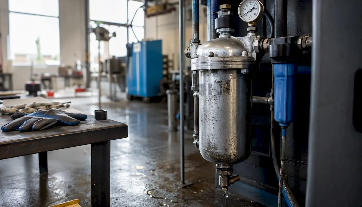
Organizational measures and operating regime in the compressor room
Technical measures only work when supplemented by a clearly defined operating regime with specific responsibility. Act No. 133/1985 Coll. on Fire Protection stipulates that responsibility for fire prevention, preventing its spread, and ensuring evacuation lies with the operator, in practice the company's statutory representative in cooperation with the fire protection technician and the compressor room operating technician. The Fire Rescue Service (HZS) acts as the relevant authority, which reviews the documentation and checks during inspections whether it corresponds to actual operating conditions.
- The statutory representative bears overall responsibility for the operation's compliance with the Fire Protection Act.
- The fire protection technician (a professionally qualified person in fire protection) prepares or coordinates the fire safety plan and proposes measures.
- The compressor room operating technician is responsible for daily compliance with operating rules and reporting deviations.
- HZS, as the relevant authority, reviews the documentation and carries out compliance inspections.
Operating rules, which every operator should have fixed in writing, include a ban on storing flammable liquids in the compressor room area, set intervals for inspections by operating staff, marking of escape routes and access paths, and clearly defined procedures for staff in case of deviations from standard operation.
- Compressor room operating regulations describing both routine and emergency procedures.
- Records of inspections and checks of technical equipment.
- Operating documentation from the compressor manufacturer, including recommended maintenance intervals.
- Procedure for emergency shutdown and evacuation of persons from the endangered area.
- Obligation to immediately report a fire or explosion to the fire and rescue service, even if it was extinguished using own resources.
A detailed overview of operating rules for compressor operators can be found in the list of safety rules for working with a compressor, which complements internal employee training.
Fire safety solution (PBŘ) and risk assessment: what it must include
PBŘ is a document that combines structural, technical, and organizational measures into a single whole assessed by the fire and rescue service, and it is indispensable for an industrial compressor room. The methodological guideline for designing and assessing the fire safety solution stipulates that the document must assess the stability of structures during a fire, the division of the building into fire compartments, the possibilities for evacuating persons, and the method of ensuring firefighting water supply.
Specifically, the PBŘ for a compressor room should include:
- Calculation of fire load and determination of the degree of fire hazard of the area.
- Description of the division into fire compartments and justification of the chosen structural fire resistances.
- Design of technical firefighting measures, including the type and placement of fire extinguishers.
- Description of internal and external access routes and staging areas for firefighting units.
- Ensuring fire water supply, i.e. the location of hydrants and their capacity.
- Clearance distances from surrounding buildings and equipment.
The fire safety documentation is prepared by a qualified designer, usually in cooperation with the operator's fire protection technician. The HZS (Fire Rescue Service), as the relevant authority, reviews the documentation as part of the building permit process or when the use changes, and during routine inspections verifies that the actual operating condition matches the documentation.
A fundamental rule that is most often violated in practice: any structural change or installation of new equipment must not reduce the level of fire safety of the building below that approved in the original fire safety documentation. Adding a more powerful compressor or dryer, or changing the piping, therefore always requires verification that the original assessment is still valid.
If you are planning to expand the compressor room, communicate with the fire safety documentation preparer already at the design stage, not after installation. Proving compliance retroactively is always more expensive and time-consuming than updating the documentation before implementation.
Key standards and legal regulations you need to know
The legal framework for fire safety in compressor rooms is based on Act No. 133/1985 Coll. on Fire Protection, the implementing decrees on technical conditions for fire protection of buildings, and Government Regulation No. 406/2004 Coll. on further requirements for safety and health protection at work in environments with explosion hazards. These regulations are legally binding, and the HZS requires compliance with them without exception during inspections.
In addition to the laws, a number of ČSN standards are used, which serve as technical background for preparing the fire safety documentation and for assessing both structural and operational parameters. The standards themselves are not always directly legally enforceable, but compliance with them is, in practice, considered the standard from which deviation is only acceptable with very good technical justification.
| Regulation / standard | What it regulates |
|---|---|
| Act No. 133/1985 Coll. | Basic obligations in fire protection, prevention, evacuation, firefighting intervention |
| Government Regulation No. 406/2004 Coll. | Classification of areas with explosion hazard, zoning |
| ČSN standards series 73 08xx | Fire safety of buildings, fire compartments, separation distances |
| ČSN EN 1012-1 | Safety requirements for compressors and vacuum pumps |
| ČSN 10 5004 | Design, installation, operation and maintenance of air compressors |
| Act No. 250/2021 Coll. and regulations No. 191/2022 Coll., 192/2022 Coll. | Designated pressure and gas equipment, inspections and checks |
The recommended study procedure is to go from the general to the specific: first Act No. 133/1985 Coll. for the framework of obligations, then Government Regulation No. 406/2004 Coll. for the assessment of explosive zones, next the ČSN standards series 73 08xx for the construction part, and finally ČSN EN 1012-1 together with ČSN 10 5004 for the technical equipment itself. The ČSN EN 1012-1 standard addresses not only machine safety but also serves as a basis for inspection reports and for demonstrating compliance during inspections.
Inspections, checks and professional competence requirements
Reserved pressure and gas equipment in the compressor room is subject to mandatory inspections under Act No. 250/2021 Coll. and its implementing regulations No. 191/2022 Coll. and No. 192/2022 Coll., which set out both the deadlines and the scope of inspections. This equipment may only be inspected by a person holding the appropriate authorization, not by an internal employee lacking the relevant qualification, and this also applies to inspections of electrical installations and fire extinguishers, where a professionally competent person with a valid certificate is required.
- Pressure vessels and gas equipment: inspections at intervals set by the implementing regulations, carried out by an authorized person.
- Electrical installations in areas with a classified zone: inspection by an electrical inspection technician specializing in environments with explosion hazards.
- Fire extinguishers: operability check at least once a year, carried out by a person authorized by the manufacturer or a service organization.
- Safety valves: functional test at the interval recommended by the manufacturer, usually annually, see the detailed guide on safety valves.
Industry practice: safety valves, condensate separation, and improper ventilation control are among the technical measures most frequently found to be deficient during operational inspections. These are not exotic faults, but things that can be detected already during a routine visual inspection, provided the operator has dedicated time for it and clear responsibility assigned.
Records of all revisions and inspections must be kept and available for inspection by the Fire Rescue Service. A proven approach is to maintain a single central record-keeping system for the entire compressor room, rather than scattered paper protocols for individual pieces of equipment, because a missing or untraceable record is assessed during an inspection the same way as an inspection not having been carried out.
Practical checklist for the operator: what to check today
Before ordering an external audit, go through your own internal inspection following this procedure, ordered by risk priority.
- Check the structural integrity and functionality of the compressor room's fire closures.
- Verify the function of both natural and forced ventilation and the emergency control from outside.
- Verify the presence and functionality of the safety valves between the compressor and the shut-off device.
- Check condensate separation and drainage, including the condition of the floor under the machine.
- Verify the electrical installation against the zone classification, if an explosive atmosphere may occur in the area.
- Check the marking of escape and intervention routes and their passability.
Priority should always go first to measures that directly prevent the occurrence and spread of fire, i.e. safety valves, ventilation and condensate, and only then to the formal aspects of documentation.
- Inspect safety valves and pressure gauges monthly by visual check, and functionally according to the manufacturer's recommendations.
- Check the condensate separator weekly.
- Check escape routes and marking at every operator shift.
- Review overall compliance with the Fire Safety Solution (PBŘ) once a year or whenever a technological change occurs.
If an inspection reveals a discrepancy between the actual condition and the approved PBŘ, do not address it as a temporary fix. Order a technical audit and, if necessary, an update of the documentation, because temporary repairs without updating the PBŘ are exactly what raises the most questions during a fire brigade (HZS) inspection. An overview of the basic requirements for a compressor room can also be found in the separate guide.
Recommendation from an operational supplier: a practical view of common mistakes
The most common mistake we encounter among compressor room operators is not missing documentation, but a discrepancy between what the PBŘ describes and what is actually installed. A company adds a second compressor, changes the piping route, or replaces an old machine with a more powerful one, and no one verifies whether the original fire load assessment is still valid. Yet this kind of minor operational change is exactly the moment when the PBŘ should be reopened, not only at the next scheduled inspection.
The second thing that surprisingly many facilities underestimate is the order of investments. When an operator has a limited budget, they often go first for visible structural modifications, while a cheaper and riskier gap remains in ventilation or condensate drainage. In terms of actual fire risk, however, functional emergency ventilation and reliable separation of oil from condensate often prevent more damage than a new fire-rated door, provided the existing construction meets at least the minimum requirements.
A preventive maintenance plan that actually works is not the most complex one, but the one that is followed. A short weekly visual check of the safety valves, separator, and floor condition will reveal most problems before they become serious. Annual inspections under Act No. 250/2021 Coll. are then a safeguard, not the main line of defence.
How Kompresory-vzduchotechnika can help you
Kompresory-vzduchotechnika is an alternative to searching for individual components from various suppliers on your own: we offer safety valves with the correct capacity, certified compressed air distribution piping, and technical consultancy all in one place, so you don't have to assemble a solution from several sources and verify component compatibility yourself.
For a compressor room where an inspection has revealed a discrepancy between the fire safety plan (PBŘ) and the actual state of the equipment, it makes sense to start with specific technical elements. We offer safety valves with parameters matching your compressor's output, consultancy in selecting the appropriate capacity, and certified piping for compressed air distribution that meets the design requirements under ČSN EN 13480-5. If you need equipment that genuinely matches your pressure rating and operating regime, browse the pneumatics and hydraulics range and choose a solution tailored to your compressor room. Our technical consultants will help you select the right valve capacity and related distribution piping, whether you are dealing with a new installation or correcting identified deficiencies.
Key takeaways for decision-making
Fire safety in a compressor room depends on the alignment between the design solution, functional technical elements (safety valves, ventilation, condensate separation), and the current fire safety plan (PBŘ), with any technological change requiring its review.
| Point | Details |
|---|---|
| Update the fire safety plan (PBŘ) with every change | Installing a new compressor or modifying the distribution system always requires verification of compliance with the fire safety plan (PBŘ). |
| Check safety valves and condensate most frequently | These elements are among the most common technical deficiencies identified during operational inspections. |
| Comply with inspection deadlines according to Act No. 250/2021 Coll. | Designated pressure and gas equipment may only be inspected by an authorized person at prescribed intervals. |
| Respect the classification of explosive zones | Government Regulation No. 406/2004 Coll. determines which electrical equipment may be used in a hazardous area. |
| Discuss technical measures with a specialized supplier | Kompresory-vzduchotechnika supplies safety valves and certified piping systems corresponding to your operating pressure. |
Useful resources and standards for inspection
When preparing or updating the Fire Safety Document, it pays off to proceed systematically from the general legal framework to the technical standards for specific equipment.
| Source | What to look for in it |
|---|---|
| Act No. 133/1985 Coll. | Basic obligations of the operator in fire protection |
| HZS methodological guide for the Fire Safety Document | The structure and content requirements of the fire safety design documentation |
| Government Regulation No. 406/2004 Coll. | The classification procedure for areas with explosion hazard |
| ČSN standards series 73 08xx | Specific parameters of fire resistance of structures and sections |
| ČSN EN 1012-1 and ČSN 10 5004 | Safety requirements for the design and operation of compressors |
| Act No. 250/2021 Coll. and Regulations No. 191/2022, 192/2022 Coll. | Deadlines and scope of inspections of designated pressure and gas equipment |
Recommended reading order: first the Fire Protection Act for the general framework of obligations, then the methodological guidance of the Fire Rescue Service for the structure of the fire safety design documentation, followed by Government Regulation No. 406/2004 Coll. for zoning, and finally the specific ČSN standards according to the type of your equipment. This procedure corresponds to the logic by which the documentation is assessed by the Fire Rescue Service itself during an inspection.
Frequently Asked Questions
What does fire safety of a compressor room mean in practice?
It refers to the compliance of structural, technical, and organizational measures, documented in the fire safety design documentation, which prevents the occurrence and spread of fire and ensures evacuation and firefighting intervention.
What is the typical fire resistance of compressor room walls?
In practice, an indicative value of F30 is often cited, but the specific requirement is always determined by a risk assessment in the fire safety design (PBŘ) based on the power and type of equipment.
Who prepares the fire safety design documentation for a compressor room?
The fire safety design (PBŘ) is prepared by a designer with professional qualification, usually in cooperation with the operator's fire protection technician, and is assessed by the Fire Rescue Service (HZS) as the relevant authority.
How often must pressure equipment in the compressor room be inspected?
The deadlines are set by implementing regulations No. 191/2022 Coll. and No. 192/2022 Coll. to Act No. 250/2021 Coll.; the inspection must be carried out by a person with appropriate authorization.
Where can I buy safety valves that comply with the standards for compressors?
Safety valves with the correct capacity for a given type of compressor are offered by Kompresory-vzduchotechnika, including advice on selecting a suitable model.
Recommended
- A list of safety rules for working with a compressor in automotive 2026 - Kompresory-Vzduchotechnika.cz
- Compressor bleeding procedure: a guide for technicians - Kompresory-Vzduchotechnika.cz
- Basic requirements for a compressor room: guide 2026 - Kompresory-Vzduchotechnika.cz
- Avoid the most common mistakes when using compressors - Kompresory-Vzduchotechnika.cz

Advantages of quick couplings: what a technician needs to know
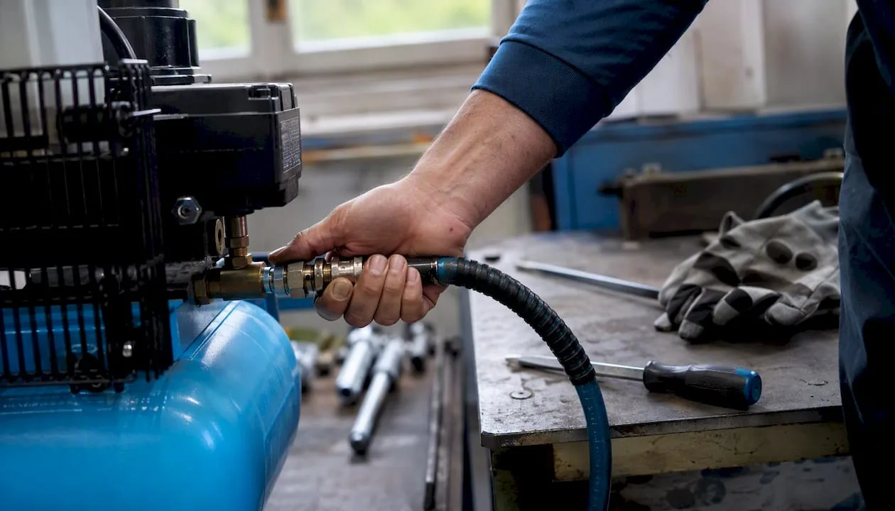
Quick couplings shorten connection time to seconds, eliminate the need for tools, and automatically seal the line when disconnected, reducing media leakage to a minimum. The same applies to both pneumatic and hydraulic systems: wherever hoses or modules are connected and disconnected repeatedly, quick couplings directly reduce downtime and operator errors. Standards ISO 7241-1 (profiles A and B) and ISO 16028 (flat-face) define the dimensions of nipples and operating pressures, so compatibility between manufacturers can be verified before purchase. Kompresory-vzduchotechnika provides technical datasheets and advice for selecting the correct series.
When to use quick couplings:
- Pneumatics: tool changes on compressor distribution lines, automated production lines, service workshops.
- Hydraulics: interchangeable modules on mobile machinery, agricultural equipment, high-pressure systems with sensitive media.
- Working with gases: special versions with flashback protection.
Professional tip: Start the selection by considering the operating pressure and the nipple profile according to ISO. Only then address the sealing material and flow rate. This significantly narrows down the number of compatible series and helps you avoid an incorrect order.
Key findings
A quick coupling correctly selected according to the ISO profile, operating pressure, and sealing material reduces service interventions, decreases media leakage, and extends the service life of the entire hydraulic or pneumatic system.
| Point | Details |
|---|---|
| Start with pressure and profile | Verify the maximum operating pressure and the ISO profile of the nipple before selecting the sealing material. |
| Drip-free design for sensitive media | Flat-face couplings according to ISO 16028 minimize air inclusion and system contamination. |
| Regular seal inspection | Worn O-rings are the most common cause of leakage; keep spare parts in stock. |
| Safety before coupling | Always reduce residual pressure and clean the face surfaces before each coupling. |
| Kompresory-vzduchotechnika | Offers technical data sheets, advice and products for complete compressed air piping systems. |
Contents
- What types of quick couplings exist for pneumatics and hydraulics?
- How do quick couplings save time, money and reduce risks?
- How to safely install and operate quick couplings?
- How to choose the right quick coupling step by step?
- How to maintain quick couplings and recognize wear?
- What are the main differences between pneumatic and hydraulic quick couplings?
- Where are quick couplings used in industry and service workshops?
- Where to find technical data sheets and product examples for quick couplings?
- Frequently asked questions
What types of quick couplings exist for pneumatics and hydraulics?
Quick couplings are divided into two main categories according to medium and working pressure. Each category has several design variants with different properties.
Pneumatic quick couplings
The most common type are push-in couplings for polyurethane or nylon tubing, where the tubing is simply pushed into the body and a locking ring secures it. For hoses with a larger diameter, bayonet or ball-type quick couplings are used, where locking is ensured by steel balls in the groove of the plug. The standard version has one shut-off valve (on the socket), while the non-drip version shuts off both sides simultaneously and prevents medium leakage upon disconnection.
Hydraulic quick couplings
Hydraulics are dominated by ball-type couplings according to ISO 7241-1 (profiles A and B) for pressures typically up to 350 bar. Flat-face couplings according to ISO 16028 have flat front faces without an internal valve, which minimizes air inclusion and system contamination. They are recommended for high-pressure and sensitive applications, where cavitation or contamination cause premature wear of components. Screw-type couplings are used where joint strength under vibration is a priority, and the high-pressure version handles pressures above 400 bar for special hydraulic applications.
| Category | Typical working pressure | Main advantage | Risk / limitation |
|---|---|---|---|
| Pneumatic push-in | low pressure | Fast assembly without tools | Sensitivity to hose pull |
| Pneumatic ball-lock | low to medium pressure | Reliable locking | Single shut-off valve |
| Pneumatic drip-free | low to medium pressure | Zero leakage on disconnection | Higher purchase price |
| Hydraulic ISO 7241-1 | medium pressure | Wide compatibility | Air inclusion on connection |
| Hydraulic flat-face ISO 16028 | higher pressure | Minimal contamination | Requires clean face surfaces |
| Hydraulic high-pressure | high pressure | Extreme pressure loads | Limited availability of seals |
Professional tip: Flat-face couplings according to ISO 16028 require absolutely clean face surfaces. A single impurity on the surface will cause leakage or damage to the seal. Wipe the surfaces before every connection and use protective caps during transport.
How do quick couplings save time, money and reduce risks?
The main advantages of quick couplings are measurable in operating costs and equipment availability. Tool-free connection shortens the time needed to change tools or modules from minutes to seconds, which is particularly noticeable during repeated service interventions on a production line or in a service workshop.
Automatic shut-off valves prevent medium leakage with every disconnection. In hydraulics, this means less oil loss, lower risk of environmental contamination and longer service life of hydraulic components. Non-drip designs go even further: they close both sides of the connection simultaneously, so no air or impurities enter the system. Reducing air inclusion directly extends the service life of pumps and valves and reduces the risk of cavitation.
Self-locking mechanisms and visual position indicators reduce human error. The operator does not need to check whether the connection is secured, because the mechanism does it automatically. The consistency of the connection is then the same regardless of who performs the assembly.
In terms of materials: stainless steel resists corrosion in wet environments, brass is the standard for pneumatics, and thermoplastic bodies reduce weight in mobile applications. Longer material life means fewer replacements of the entire coupling and lower overall maintenance costs.
Professional tip: Always choose non-drip or flat-face designs when the system contains a sensitive hydraulic medium (biodegradable oils, food-grade lubricant) or when system contamination is unacceptable. For standard pneumatics in a workshop, a standard ball coupling is sufficient.
How to safely install and operate quick couplings?
Safety when working with quick couplings depends on following several specific steps. Underestimating preparation before connection is the most common cause of injuries and equipment damage.
Before connection:
- Check the compatibility of the working pressures on both sides of the connection. Never connect components with different maximum pressures without knowing the weaker link.
- Verify that the plug profile matches the socket profile (ISO 7241-1 A/B, ISO 16028 or another standard).
- Clean the front faces of dirt, oil and moisture.
- Reduce residual pressure in the system before connecting. Use a static pressure eliminator or slowly open the bleed valve.
- Fit protective caps on unused connections.
When disconnecting:
- First release the pressure in the system to operating minimum or zero.
- Disconnect the coupling with a smooth movement according to the design principle (push-pull, ring rotation).
- Immediately fit protective caps on both sides.
- Check that the shut-off valves have properly stopped the flow.
Personal protection:
- Safety glasses are mandatory when working with pressure systems.
- When working with flammable gases, use quick couplings with flashback protection and comply with regulations for working in explosion-hazard environments.
- Gloves protect when handling hot or chemically aggressive media.
The most common mistake is connecting under pressure without prior depressurization. The result is often an uncontrolled hose whip or seal damage at the first connection.
How to select the correct quick coupling step by step?
Selecting the correct quick coupling comes down to six criteria in this order:
- Working pressure and safety factor. The maximum operating pressure of the system must be lower than the rated pressure of the coupling. Account for pressure spikes during the compressor duty cycle.
- Nipple profile and compatibility. ISO 7241-1 A or B, ISO 16028, or a manufacturer-specific profile. Different profiles are not interchangeable.
- Flow and pressure drop (Cv). Too small a nominal bore causes pressure drop and reduces the performance of the tool or actuator.
- Medium and chemical resistance of the seal. NBR for mineral oils and air, Viton for aggressive liquids and higher temperatures, EPDM for water and steam.
- Operating temperature. Standard NBR seals work approximately from -20 °C to +100 °C. Extreme temperatures require special materials.
- Cyclic loading and corrosion resistance. A high number of cycles per shift requires a more durable body material and a higher-quality surface treatment.
Checklist questions for quick selection:
- Can it be connected with one hand? (Necessary for mobile machines and work in gloves.)
- Is drip-free design needed? (Sensitive medium, food industry operation, hydraulics with biological oils.)
- What nipple profile does the existing system have?
- What sealing does the medium require?
- Are there vibrations or dynamic loads in the system? (Consider a screw-type or locking design.)
Expanding existing pneumatic equipment is simpler if you choose couplings from standardized series with available replacement seals from the start.
How to maintain quick couplings and recognize wear?
Regular inspection of quick couplings prevents unplanned downtime. Recommended inspection points:
- Visual inspection of seals: cracks, deformation, or hardening of O-rings indicate the need for replacement. Rubber that has lost its elasticity does not seal reliably even at low pressure.
- Leak test: after connecting, apply soap solution or use a leak detector. Bubbles or pressure drop indicate a leak.
- Inspection of locking rings and balls: worn balls or a deformed locking ring cause unintentional disconnection under pressure.
- Cleanliness of face surfaces: dirt on the surfaces of flat-face couplings causes scratches on the seal and permanent leakage.
- Body corrosion: surface corrosion is cosmetic, corrosion in the threaded section or on the face surface is a functional problem.
The most common failure is worn O-rings. Replacement is simple: depressurize the system, remove the coupling, replace the O-ring with an identical part (same material, same wire diameter and inner diameter) and lightly lubricate the O-ring with compatible grease before assembly.
Professional tip: Keep a stock of spare O-rings for each type of coupling in operation. Downtime caused by waiting for a seal worth a few crowns is unnecessary. When ordering a new coupling, always order a set of spare seals as well.
When servicing, use dust caps on both sides of the disconnected coupling. They prevent dirt from entering the system and shorten the cleaning time before reconnection.
What are the main differences between pneumatic and hydraulic quick couplings?
The choice between a pneumatic and hydraulic quick coupling is not just a matter of medium. They differ in working pressures, flow rates, sealing requirements and the risk of contamination.
Pneumatic couplings tolerate a certain amount of moisture and dirt in the medium better than hydraulic ones. Hydraulic flat-face couplings according to ISO 16028 are the most demanding in terms of design: a flat face without an internal valve minimizes air inclusion and extends the service life of hydraulic components, but requires absolute cleanliness at every connection.
When to choose which type:
- Flat-face ISO 16028: high-pressure hydraulics, sensitive media, mobile machines with interchangeable working tools.
- ISO 7241-1 A/B: standard hydraulic applications where compatibility and availability of spare parts are a priority.
- Push-pull pneumatic: service workshops, production lines, compressed air distribution up to 16 bar.
Where are quick couplings used in industry and service workshops?
Quick couplings in industry cover a very wide range of applications. Each has specific design requirements.
Production lines and automation: Quick replacement of pneumatic tools or actuators during line changeover. The key property is connection consistency and the ability to replace with one hand without interrupting production. Integration into pneumatic automation requires standardized profiles and reliable locking.
Service workshops: Connecting pneumatic tools (impact wrenches, grinders, guns) to the compressor distribution system. Standard ball-type couplings with NBR seals are sufficient. Emphasis on ergonomics and the ability to change tools with one hand.
Mobile machinery and agricultural equipment: Replacing hydraulic working attachments (shovels, cutters, buckets) directly on the machine. Priorities are safeguards against accidental disconnection and emergency release mechanisms when the hose is stretched. Push-pull or automatic disconnection under overload protects both the operator and the machine.
Work with flammable gases: Special designs with flashback protection and antistatic materials. These couplings must comply with relevant safety standards for environments with explosion hazards. Standard pneumatic or hydraulic couplings are not suitable for this application.
Laboratory and food industry applications: Non-drip stainless steel design with EPDM seals for media where contamination by oil or impurities is unacceptable.
Professional tip: For mobile machinery and agricultural equipment, always consider a push-pull mechanism or automatic emergency disconnection when the hose is stretched. This feature protects the hydraulic circuit from damage in case of accidental hose overextension.
Where to find technical data sheets and product examples for quick couplings?
Technical data sheets are an essential tool for verifying parameters before purchase. The Kompresory-vzduchotechnika website provides datasheets for specific product lines, for example ES DN7.2 Lüdecke quick couplings, where you can check the nominal bore (DN7.2), maximum working pressure, flow coefficient Cv, body material, and seal type.
What to read first in the datasheet:
- Maximum working pressure (bar): must exceed the system's operating pressure, including peaks.
- Nominal bore / flow rate (Cv or Qn): determines whether the coupling will restrict the flow of the medium.
- Seal material: NBR, Viton, or EPDM depending on the medium and temperature.
- Nipple profile: ISO designation or manufacturer-specific profile for compatibility verification.
- Operating temperature range: critical for outdoor or high-temperature applications.
Standards ISO 7241-1 and ISO 16028 are publicly available through national standardization bodies. Manufacturers such as Lüdecke publish dimensional drawings and CAD files on their websites, which are useful when designing air distribution systems.
When selecting a quick coupling, always verify three parameters directly in the datasheet: maximum working pressure, nipple profile according to ISO, and seal material. These three values determine the compatibility and safety of the connection. Everything else is secondary.
For technical inquiries, catalog requests, or dimensional drawings, contact Kompresory-vzduchotechnika technical support directly through the website.
A view from an expert salesperson and service technician
In practice, quick coupling selection most often goes wrong at one point: a technician selects a coupling based on hose diameter but forgets to verify the nipple profile and maximum pressure. The result is either an incompatible pair or a coupling that only lasts until the first pressure spike. Prioritize pressure and profile, address the seal afterward.
A non-drip design costs more, but in sensitive applications, this investment pays off at the first service intervention, when the system remains clean. For standard pneumatics in a workshop, a standard ball coupling is fully sufficient and does not unnecessarily increase operating costs.
Quick couplings and accessories for pneumatics in one place
Kompresory-vzduchotechnika offers direct access to technical products for compressed air distribution: from pipes for compressed air distribution through air treatment units to pneumatic tools. Technical support will help with selecting the correct quick coupling according to operating parameters, provide the datasheet for the specific series, and advise on seal compatibility.
To place an order or make a technical inquiry, visit the Kompresory-vzduchotechnika website or contact technical support directly. Catalogs, dimensional drawings, and consulting for custom distribution system design are available.
Frequently Asked Questions
What are the main advantages of quick couplings over fixed connections?
Quick couplings allow tool-free connection and disconnection within seconds, automatically shut off the line when disconnected, and reduce media leaks. Fixed connections are suitable for permanent installations, while quick couplings are suited for situations where hoses or modules are exchanged repeatedly.
What is the difference between ISO 7241-1 and ISO 16028?
ISO 7241-1 defines ball-type hydraulic quick couplings with an internal valve (profiles A and B), while ISO 16028 describes flat-face designs without an internal valve, featuring flat front surfaces. Flat-face minimizes air inclusion and contamination, making it suitable for sensitive and high-pressure hydraulic applications.
How can I tell that a quick coupling seal is worn out?
Visible cracks, deformation, or hardening of the O-ring are clear signs. A functional test involves applying soapy solution to the connection under pressure: bubbles or a pressure drop indicate a leak and the need to replace the seal.
Can pneumatic and hydraulic quick couplings be interchanged?
No. They differ in working pressures, plug profiles, seal materials, and design construction. Interchanging them can cause leaks, system damage, or injury. Always verify the ISO profile and maximum pressure in the datasheet.
Where can I find technical datasheets for quick couplings in Czech?
Technical datasheets for specific product lines are available on the Kompresory-vzduchotechnika website, directly from the manufacturer (e.g. Lüdecke), or through technical support. ISO standards are available through the Czech Office for Standards, Metrology and Testing (ÚNMZ).
Recommended
- Quick couplings and plugs for fast and reliable connection
- What is pneumatic lubrication: a guide for technicians - Kompresory-Vzduchotechnika.cz
- I.e. pneumatic connection: types, functions and practice - Kompresory-Vzduchotechnika.cz
- Advantages of pneumatic systems: Why use them in production - Kompresory-Vzduchotechnika.cz

Home workshop projects with a compressor: ideas and parameters for DIY enthusiasts

An air compressor can handle a surprising number of tasks in a home workshop: airbrushing and model painting, spraying furniture or a fence, inflating tyres and mattresses, blowing and cleaning parts, working with a nail gun or pneumatic screwdriver, a home beer tap, and even making ice cream. For most of these projects, an oil-free piston compressor with a flow rate of 100–250 l/min, a working pressure of 6–8 bar, and an air tank of 24–50 l is sufficient. Inspiration for home projects with a compressor is therefore wide-ranging, but each project has different requirements, and it is precisely these requirements that determine the choice of machine.
- Airbrushing / model painting: 20–50 l/min, 1.5–3 bar, air tank 6–24 l
- Spraying furniture or a fence (HVLP gun): 100–200 l/min, 2–4 bar, air tank 24–50 l
- Inflating tyres and mattresses: 30–80 l/min, 6–8 bar, air tank 6–24 l
- Blowing and cleaning parts: 50–150 l/min, 4–6 bar, air tank 24 l
- Nail gun / pneumatic screwdriver: 100–200 l/min, 6–8 bar, air tank 24–50 l
- Home beer tap: integrated compressor, operating pressure in the system
- Home ice cream maker with compressor: built-in unit, no external air supply
- Light automotive repair work (pneumatic impact wrench): 200–300 l/min, 6–8 bar, air tank 50 l+
If you are unsure about your choice, always base it on the highest consumption of the tool in the setup, add a 20–30% flow reserve, and choose an air tank that will cover at least 30 seconds of continuous draw without the motor starting.
Key takeaways
An air compressor with a flow rate of 100–250 l/min, a pressure of 6–8 bar, and an air tank of 24–50 l will cover most common hobby projects, from airbrushing to using a nail gun.
| Point | Details |
|---|---|
| Flow rate determines the selection | Always base your calculation on the highest tool consumption and add a 20–30% flow rate reserve. |
| Duty cycle is a critical parameter | Portable compressors with a 50% duty cycle will overheat under continuous draw; for spraying larger areas, choose higher capacity. |
| Air receiver safety | Never use modified tanks without inspection; a safety valve is mandatory for every assembly. |
| Accessories are not optional | A condensate separator, regulator, and filter are essential for quality results and tool protection. |
| Kompresory-vzduchotechnika | Offers oil-free and oil-lubricated compressors, accessories, and service with technical advice for selection according to the project. |
Contents
- What types of compressors are suitable for a home workshop?
- How to choose a compressor according to a specific project?
- Specific home projects with a compressor: instructions and safety
- What accessories do you need for safe work with a compressor?
- How to take care of a compressor and work with it safely?
- When to buy a factory-made compressor and when to opt for a DIY solution?
- The most common mistake made by DIYers: underestimating the duty cycle
- Kompresory-vzduchotechnika will help you with selection and service
- Useful resources and further reading
- Frequently asked questions
What types of compressors are suitable for a home workshop?
The choice of the right type of compressor depends on the frequency of use, the required flow rate, and the type of project.
Oil-free piston compressors are the most common choice for hobby DIYers. They do not require oil changes, the air is cleaner, and therefore they are suitable for airbrushing, food applications (home beer dispensers) and inflating. For intermittent work in the workshop, however, this is usually not an issue.
Oil-lubricated piston compressors have a longer service life and better tolerate frequent or longer working cycles. They are suitable for regular work with pneumatic tools, grinding or spraying larger surfaces. They require regular oil changes and a condensate separator so that oil does not enter the air distribution system.
For home hobby use they are usually oversized and more costly, but for a well-equipped workshop with higher air consumption they make sense. A more detailed comparison of parameters is offered by the guide to choosing an air compressor.
Portable compressors and small desktop units are suitable for work outside the workshop: inflating in the garden, airbrushing en plein air, or cleaning furniture before varnishing. Mobility comes at the expense of air tank capacity.
A special category is integrated compressors in home beer dispensing equipment and ice cream makers. These are not intended for connecting pneumatic tools; they function as closed systems for a specific appliance.
For hobby use, small oil-free units with a flow rate of 100–250 l/min and an air tank of 24–50 l are sufficient for common applications.
How to choose a compressor for a specific project?
The correct selection process is straightforward if you go through it step by step.
- Define the tool or project. Every pneumatic tool has the required flow rate (l/min or CFM) and working pressure (bar or PSI) stated on the label or in the manual. Start here.
- Verify the working pressure. The compressor must reach a pressure at least 1–2 bar higher than the operating pressure of the tool, so that the regulator has room to regulate.
- Calculate the required flow rate. If you plan to use multiple tools at the same time, add up their flow rates. Add a 20–30% reserve.
- Choose the air tank volume and duty cycle. A larger air tank means longer work without the motor switching on. Tools with intermittent draw (nail gun) can manage with a smaller tank; continuous draw (grinder, spray gun) requires a larger one.
Approximate parameters for common hobby projects:
| Tool / project | Flow rate (l/min) | Working pressure (bar) | Recommended air tank (l) |
|---|---|---|---|
| Airbrush | 20–50 | 1,5–3 | 6–24 |
| HVLP spray gun | 100–200 | 2–4 | 24–50 |
| Tyre inflation | 30–80 | 6–8 | 6–24 |
| Blow gun | 50–150 | 4–6 | 24 |
| Nail gun | 100–200 | 6–8 | 24–50 |
| Pneumatic screwdriver | 150–200 | 6–8 | 24–50 |
| Impact wrench | 200–300 | 6–8 | 50+ |
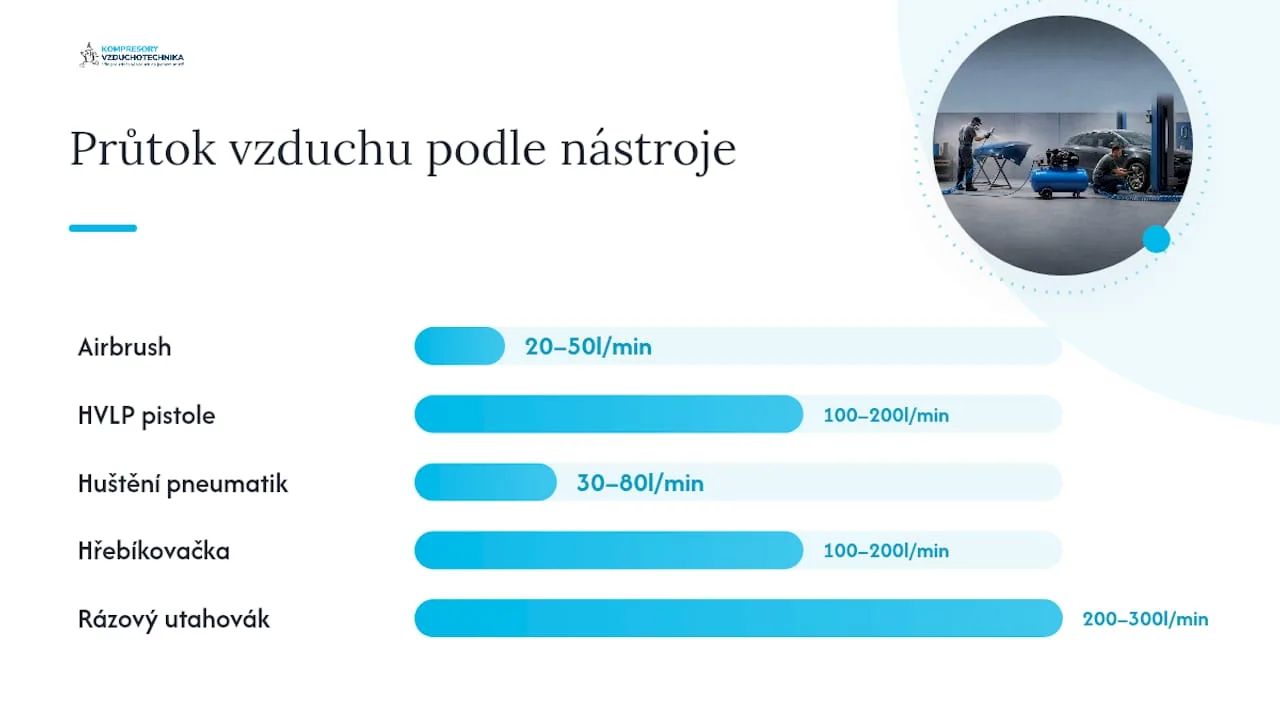
For airbrush work and inflating, a small oil-free compressor up to 50 l/min is sufficient. Once you add an impact wrench or HVLP gun, it's time to move to an oil-lubricated or larger oil-free unit with an air tank of at least 50 l. More detailed technical factors for selecting a larger unit are described in the guide to choosing an industrial compressor.
Specific home projects with a compressor: instructions and safety
Ideas for home projects with a compressor vary in requirements and risk. Each card below states what you actually need.
Airbrush and model painting
Parameters: 20–50 l/min, 1.5–3 bar, air tank 6–24 l. Accessories: fine moisture filter, regulator with pressure gauge, 6 mm hose. Time and costs: purchase price of an airbrush set from approx. CZK 1,500, compressor from CZK 3,000. Work in a ventilated room or with a respirator, paints contain solvents.

Spraying furniture or a fence (HVLP gun)
Parameters: 100–200 l/min, 2–4 bar, air tank 24–50 l. Accessories: condensate separator, regulator, HVLP gun, 8–10 mm hose. Always filter out moisture before spraying, otherwise the paint will curdle. Work outdoors or in a well-ventilated workshop, away from open flame.
Inflating tires and mattresses
Parameters: 30–80 l/min, 6–8 bar, air tank 6–24 l. Accessories: pressure gauge, inflation gun with adapters. Never exceed the maximum tire pressure stated on the sidewall. Check the pressure when cold, not after driving.
Blowing off and cleaning parts
Parameters: 50–150 l/min, 4–6 bar, air tank 24 l. Accessories: blow gun, safety glasses. Never aim the air stream at your skin or into your ears. Use hearing protection, the noise from blowing exceeds 85 dB.
Working with a nail gun or pneumatic screwdriver
Parameters: 100–200 l/min, 6–8 bar, air tank 24–50 l. Accessories: quick couplings, 8 mm hose, safety glasses. Always depressurize the system before disconnecting the hose. A nail gun will fire a nail even with an unintentional press, so never aim it at people.
Home beer tap system
Home draft beer systems with an integrated compressor keep beer under optimal pressure and extend freshness for several days with proper sanitation. The compressor here functions as both the primary pressure source and a backup source for gas systems. Models such as the Pygmy series combine a tap, cooling, and compressor in one unit, allowing dispensing without an external CO₂ supply. Safety: clean the lines and tap regularly, otherwise bacteria will multiply. Use only components certified for food contact.
Professional tip: To prevent beer from foaming during dispensing, set the system pressure exactly according to the keg manufacturer's recommendations, usually 0.5–1 bar, and keep the beer temperature below 5 °C. Higher temperature or pressure will cause excessive foaming.
Home ice cream maker with a compressor
Ice cream makers with a built-in compressor prepare ice cream within an hour and can handle portions of up to one and a half liters without pre-freezing the bowl. This is a closed system that requires no external air supply. Safety: do not place the appliance in an enclosed space without ventilation, as the compressor generates heat.
Light automotive repair work
Parameters: 200–300 l/min, 6–8 bar, air tank 50 l+. Accessories: impact wrench, pneumatic grinder, 10 mm hose, quick couplings, safety glasses, and hearing protection. This is the most demanding hobby application. A small portable compressor is not sufficient here; you need a stationary oil-lubricated or larger oil-free unit.
When working with pneumatic tools in the workshop, always check the tightness of connections before starting up. A leak of pressurized air can cause injury and unnecessarily strains the compressor.
What accessories do you need for safe work with a compressor?
The right accessories determine both the quality of the result and safety. A basic setup for a home workshop includes:
- Inlet air filter: captures dust and impurities at the intake, extending the compressor's service life.
- Condensate separator (moisture separator): separates water from the compressed air, essential before spraying and airbrushing.
- Pressure regulator with pressure gauge: allows you to set the precise working pressure for each tool. Details on proper regulation are described in the guide to pressure regulator applications.
- Safety valve: protects the tank from exceeding the maximum pressure, a mandatory component of every setup.
- Check valve: prevents backflow of air from the tank into the compressor when switched off.
- Hoses: PVC hoses are lightweight and cheap, suitable for airbrushing and inflating. Rubber hoses handle oil and higher temperatures better and are recommended for oil-lubricated compressors and auto repair shops. Diameter 6 mm for airbrushing, 8–10 mm for tools.
- Quick couplers: allow fast tool changes without depressurizing the entire system. Choose a type matching the diameter of the hose and the tool.
- Oil separator: necessary for oil-lubricated compressors used before airbrushing or food-industry applications, so that oil does not get into the product.
- Ear protection and safety glasses: basic personal protection for any work with a compressor.
How to maintain a compressor and work with it safely?
Regular maintenance extends the compressor's lifespan and prevents failures. A compressor and DIY projects go hand in hand, but only when the machine runs reliably.
Daily checks:
- Check the pressure in the tank before starting.
- Visually inspect the hoses and connections for damage.
- After finishing work, drain the condensate from the tank by opening the drain valve. Water in the tank causes corrosion.
Weekly and monthly tasks:
- Check the function of the safety valve by manually testing it.
- Clean or replace the intake air filter.
- For oil-lubricated compressors, check the oil level and its colour. Replace dark or cloudy oil. The bleeding procedure and service tasks are described in the compressor bleeding guide.
Basic safety rules:
- Never exceed the maximum working pressure of the tank stated on the label.
- Do not use modified tanks (for example from fire extinguishers or old refrigerators) without professional inspection and certification. When building a DIY assembly from a refrigerator, installing a safety valve and having the pressure vessel inspected is a condition for safe operation, otherwise there is a risk of bursting.
- Work in a ventilated room, the compressor produces heat and noise.
- Pressure vessels are subject to regular inspection according to applicable regulations. Care of the pressure vessel is described in detail in the guide to maintaining a compressor tank.
Never carry out welding or mechanical modifications to the pressure vessel without professional assessment. A damaged or improperly modified tank can fail without warning.
When to buy a factory-made compressor and when to opt for a DIY solution?
The decision between a factory-made compressor and a DIY build depends on several specific criteria.
- Frequency of use. Airbrushing once a month or occasional inflating can be handled even by a simple DIY setup built from a refrigerator compressor, which delivers approximately 0.7–1 CFM. For regular work with pneumatic tools, a factory-certified unit is safer and more economical in terms of servicing.
- Required flow rate and duty cycle. DIY builds have limited power and duty cycle. Tools with higher air consumption (impact wrench, pneumatic grinder) require a factory compressor with guaranteed parameters.
- Food-grade purity. A home beer tap or ice cream preparation requires air free of oil and contaminants. An oil-free factory compressor or an integrated unit is the only reliable choice here.
- Pressure vessel safety. Homemade tanks from refrigerators or fire extinguishers without inspection are a risk. Factory compressors have certified tanks with safety valves set by the manufacturer.
- Service availability. A factory-made machine can be serviced by the supplier. A DIY build depends on the availability of spare parts and your own knowledge.
An experienced DIYer recommends a combined approach: DIY for low-energy one-off applications, factory-certified units for tools with high air consumption, due to safety, performance, and service availability. In case of any doubts about safety or performance, the correct choice is a factory-made solution and consultation with a specialist.
The most common mistake made by DIYers: underestimating duty cycle
Duty cycle is the parameter most often underestimated by DIYers. If you load it with continuous draw (spraying a large area, grinding), it will overheat and the thermal protection will shut it down, or the motor windings will be damaged.
A practical leak test is simple: pressurize the system, close off the supply, and watch the pressure gauge for 5 minutes. If the pressure drops, look for a leak using soapy water on joints and quick-connect couplings. After each use, drain the condensate from the tank and let the compressor run empty before switching it off. These two measures will significantly extend the machine's service life.
Kompresory-vzduchotechnika will help you with both selection and service
Choosing the right compressor for a specific project isn't always straightforward, especially if you plan to combine multiple tools or expand your workshop gradually. Kompresory-vzduchotechnika offers technical consultation for selecting oil-free and oil-lubricated compressors, supply of accessories (hoses, filters, regulators, quick-connect couplings), and regular servicing including pressure vessel inspections.
The process is simple: describe your project and the tools you plan to use, and the Kompresory-vzduchotechnika team will propose a suitable setup with specific parameters. The entire range of pneumatics and air technology is available online, with the option of consultation before purchase. If you are not sure whether your existing compressor can handle the planned project, simply send its technical parameters and the service team will assess whether an upgrade is necessary or whether new accessories will suffice.
Useful resources and further reading
- Home use of compressors: options and how to choose the right one — Kompresory-vzduchotechnika
- Examples of compressor use: a guide for workshops and production — Kompresory-vzduchotechnika
- Guide to maintaining a compressor tank — Kompresory-vzduchotechnika
- List of the best compressors 2026: a buying guide — Kompresory-vzduchotechnika
- Basic requirements for a compressor room — Kompresory-vzduchotechnika
Frequently Asked Questions
What compressor is sufficient for airbrushing at home?
For airbrushing, a small oil-free compressor with a flow rate of 20–50 l/min and a working pressure of 1.5–3 bar is sufficient; an air tank of 6–24 l will ensure stable and even pressure without pulsation.
How do I know if a compressor can handle my tool?
How often should condensate be drained from the tank?
Drain condensate after each use by opening the drain valve at the bottom of the tank; water in the tank causes corrosion and shortens the compressor's service life.
Is a DIY compressor made from a fridge compressor safe?
A DIY setup made from a fridge compressor works for low-energy applications, but it requires installing a safety valve and having the pressure vessel professionally inspected; without these precautions, there is a risk of the tank bursting.
Where can I get accessories and advice for a home workshop?
Kompresory-vzduchotechnika offers a complete range of accessories (filters, regulators, hoses, quick couplers) as well as technical advice for choosing the right setup for a specific project.
Recommended
- Home use of compressors: options and how to choose the right one - Kompresory-Vzduchotechnika.cz
- List of small compressors and their benefits for workshop and construction site - Kompresory-Vzduchotechnika.cz
- Examples of compressor use: a guide for the workshop and production - Kompresory-Vzduchotechnika.cz
- Basic requirements for a compressor room: guide 2026 - Kompresory-Vzduchotechnika.cz


Compressor condensate: Czech Republic laws for operators
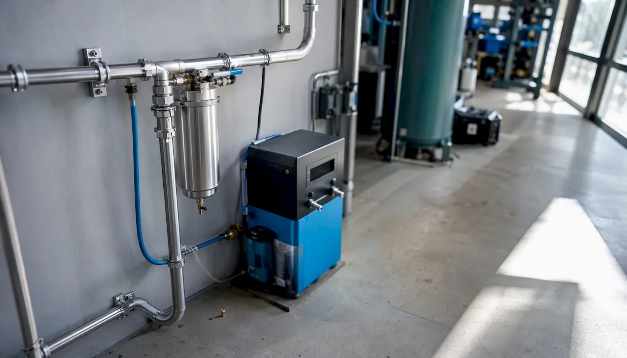
Condensate from oil-lubricated compressors must not be discharged into the public sewerage system without treatment. This obligation is imposed by Act No. 254/2001 Coll. (Water Act) in conjunction with the sewerage regulations of the public sewerage operator and technical standards ČSN EN 12056-1 and ČSN 75 6760. The condensate contains trace amounts of mineral oil, which qualify it as contaminated wastewater, and therefore direct discharge is prohibited.
What you must ensure:
- Install an oil–water separator or another approved method of condensate treatment before discharging it into the sewerage system.
- Neutralize condensate with a pH below 6.5 (typically condensate from condensing boilers or certain types of compressors) before discharging it into sewers sensitive to acidic water.
- Keep records of the amount of condensate, measurement results, and service interventions on the separator.
- Ensure the removal of separated oil by an authorized hazardous waste processor.
The first step is to verify the sewerage regulations of your public sewerage operator and include the remedy in the nearest operational audit.
Key findings
The compressor operator must ensure condensate treatment by means of a separator or neutralization, keep records, and hand over the separated oil to an authorized hazardous waste processor.
| Point | Details |
|---|---|
| Prohibition of direct discharge | Untreated condensate from oil-lubricated compressors must not be discharged into the sewer system; this obligation is imposed by Water Act No. 254/2001 Coll. |
| pH limit and neutralization | Condensate with a pH lower than 6.5 requires neutralization before discharge into sewers without acid-resistant protection. |
| Separator as the main solution | Physical separation (adsorption, filtration) achieves a residual oil content below the operational target of ~15 mg/l and is the preferred method. |
| Records and hazardous waste | The oil fraction is hazardous waste; keep records of handover to the processor for at least 5 years. |
| Kompresory-vzduchotechnika | Offers audit, supply of separators, installation, and service contracts to ensure compliance with Czech legislation. |
Contents
- What Czech laws and standards apply to compressor condensate?
- What specific limits must treated condensate meet?
- What technical solutions are available for condensate treatment?
- What are the installation and operational requirements for condensate piping?
- How to proceed step by step when ensuring compliance with regulations?
- How to monitor condensate quality and handle separated oil?
- When will the investment in a separator pay off?
- Editorial perspective: where operators most often make mistakes
- Kompresory-vzduchotechnika will help you with the whole process
- Frequently Asked Questions
What Czech laws and standards apply to condensate from a compressor?
The legal framework consists of three layers: the law, implementing regulations, and technical standards.
Act No. 254/2001 Coll. (the Water Act) establishes the basic rules for the discharge of wastewater. On its basis, the water authority issues discharge permits and may impose conditions or sanctions. Condensate from oil-lubricated compressors contains mineral oils, and therefore falls into the category of contaminated wastewater, the discharge of which without prior treatment is prohibited by law.
Act No. 274/2001 Coll. on Water Supply and Sewerage Systems introduces the institute of the sewerage regulations. Every operator of a public sewerage system issues its own sewerage regulations, which specifically define the permissible pollution limits, permitted substances, and technical conditions for connection. The sewerage regulations are binding for you as a producer of wastewater. Without studying them, you do not know what specific limits apply to your connection.
ČSN 75 6760 governs internal drainage systems and the technical requirements for condensate discharge, including the requirement for neutralization when pH is below 6.5. ČSN EN 12056-1 then sets out the principles of gravity drainage inside buildings. Both standards are mandatory when designing and installing condensate piping.
Key fact: Condensate from oil-lubricated compressors is technically classified as waste containing mineral oils. Without a separator or other treatment, this constitutes a direct violation of the Water Act, not merely a technical shortcoming.
Government Regulation No. 401/2015 Coll. supplements the Water Act and sets emission standards for the discharge of wastewater. For industrial operations, the limits for non-polar extractable substances (NEL) are particularly relevant, and treated condensate must fall below these limits.
What specific limits must treated condensate meet?
Three parameters determine whether you may discharge condensate directly into the sewer system after treatment.
| Parameter | Typical value for untreated condensate | Requirement for discharge |
|---|---|---|
| Oil content (NEL) | Trace amounts up to units of mg/l | Usually ≤ 15 mg/l (according to the sewerage regulations) |
| pH | Condensing boilers, some compressors | ≥ 6.5 for sewers without acid-resistant protection |
| Temperature | Depending on operation | According to sewerage regulations (usually ≤ 40 °C) |
The value of 15 mg/l for residual oil content is an operational reference target stated by separator manufacturers, which corresponds to common sewerage regulation requirements. Your specific limit may be stricter, so always check the sewerage regulations.
Condensate from condensing boilers and some types of compressors usually has an acidic pH lower than 6.5. The standard ČSN 75 6760 states that if the pH is lower than 6.5, neutralization must be carried out unless the sewers are made of acid-resistant material. Concrete and stoneware sewers are damaged by acidic condensate, while plastic ones (PVC, PP) are more resistant, but here too the sewerage regulations are decisive.
The minimum dimension of the condensate piping depends on the flow rate and the length of the route. DN 32 or DN 40 is commonly used for condensate drainage from compressors; the specific value is determined by the project or by ČSN EN 12056-1 based on flow rate calculation.
What technical solutions are available for condensate treatment?
Four main technologies cover most operational situations.
Oil–water separators are the most widespread solution for oil-lubricated compressors. They work on the principle of physical separation: the condensate first passes through a sedimentation chamber, where coarse oil droplets are separated, and then through a filtration layer made of adsorption media (activated carbon or special polypropylene fibers). The result is water with an oil content below the operational limit and a concentrated oil fraction, which is drained into a collection container. Physical separation is the preferred method because it does not introduce chemical substances into the process and provides stable results.
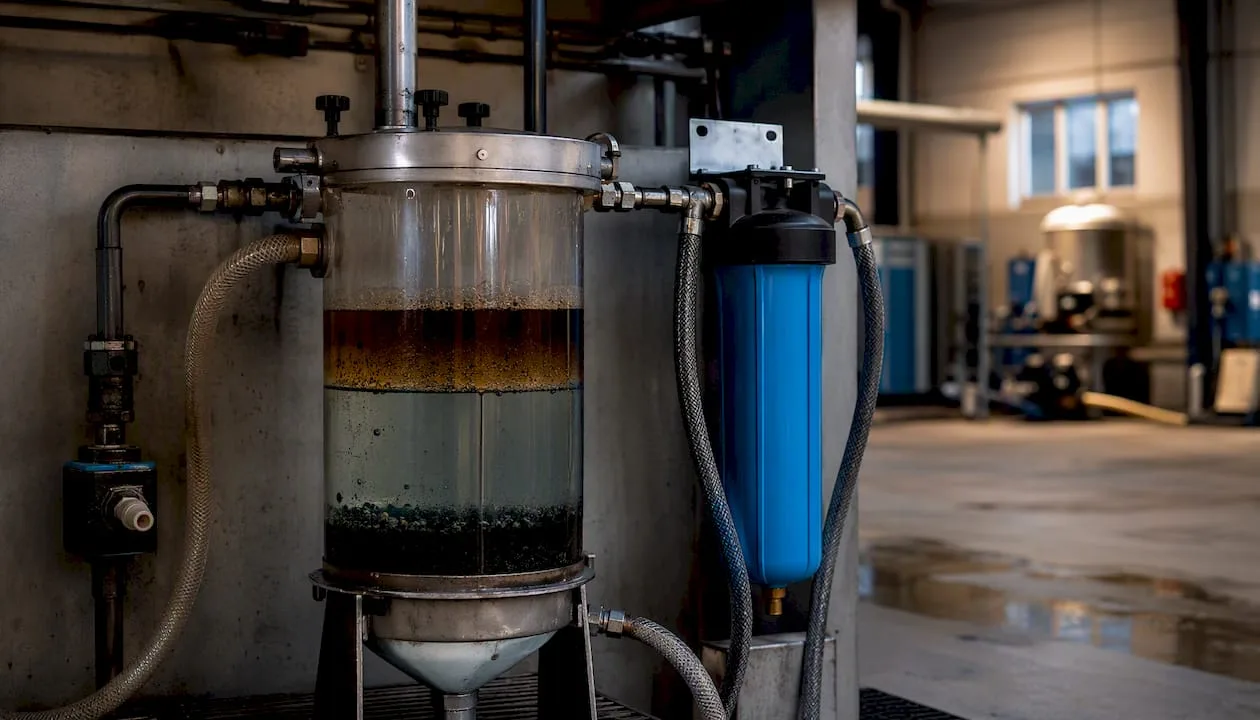
Neutralization boxes address the problem of acidic pH. The condensate flows through a layer of neutralization granulate (usually calcium or magnesium carbonate), which raises the pH to an acceptable value. They are used independently with condensing boilers or in combination with a separator where the condensate is both acidic and oily.
Combined systems integrate a separator and neutralization into a single device. For facilities with multiple condensate sources (compressor, condensing boiler, compressed air dryer), this is the most practical choice.
Automatic condensate drains are not a treatment technology but a key operational component. They ensure regular and controlled discharge of condensate from the pressure vessel, air tank or separator into the separator. Without a functioning drain, condensate overflows or accumulates, leading to leaks outside the system. Drains require regular checks of flow capacity and cleanliness of the float or electronic mechanism.
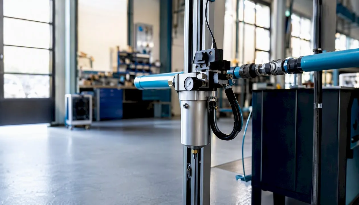
Professional tip: When selecting a separator, always base your choice on the maximum hourly condensate volume, not the average. A compressor operating in summer with high air humidity produces significantly more condensate than in winter. An undersized separator cannot filter the entire flow and allows oil to pass into the sewage system.
What are the installation and operational requirements for condensate piping?
Proper installation is a prerequisite for the functionality of the entire system. Piping errors cause leaks, odors, or backflow of sewer gases.
-
Pipe sizing: For condensate discharge from compressors, a minimum of DN 32 is used, and DN 40 or more for larger facilities. The piping must be sized for the maximum condensate flow with a safety margin.
-
Pipe slope: A minimum slope of 1% (1 cm per 1 m of length) ensures gravity drainage without condensate accumulation. For longer runs or insufficient slope, a pumping station must be used.
-
Water trap seal (siphon): Every connection to the sewage system must be fitted with a siphon with a water seal. With intermittent condensate discharge, there is a risk of the siphon drying out and sewer gases entering the facility. The solution is regular refilling with water or installing a siphon with anti-drying protection (glycerine filling or mechanical flap).
-
Funnel (open rim): Connection of the condensate piping to the sewage system is made via a funnel, not by direct connection. The funnel allows visual inspection of the flow and prevents backflow.
-
Pipe material: For acidic condensate (pH < 6.5), piping made of PP or HDPE is used. Steel or cast iron piping is corroded by acidic condensate.
-
Cleaning fittings: A cleaning fitting must be installed on every longer section of piping and before every change of direction, for access in case of blockage or inspection.
-
Regular separator maintenance: The separator's filter medium is replaced according to the manufacturer's instructions, usually once a year or upon reaching maximum capacity. The oil collection container is emptied as needed, but at least once a quarter. Every service intervention is recorded in the operating log.
How to proceed step by step when ensuring compliance with regulations?
A systematic approach minimises the risk of omissions and unnecessary costs.
-
Audit of condensate sources: Map all equipment producing condensate (compressors, dryers, condensing boilers). For each source, determine the estimated hourly volume of condensate and the current method of its discharge.
-
Sampling and measurement: Have a laboratory analysis of the condensate carried out: oil content (NEL), pH and temperature. Compare the results with the limits set out in the sewerage regulations of your public sewerage operator.
-
Studying the sewerage regulations: Request the sewerage regulations from the public sewerage operator or find them on their website. Focus on the limits for NEL, pH, temperature, and the conditions for connecting industrial wastewater.
-
Technology selection: Based on the measurements and limits, decide whether an oil–water separator is sufficient, or whether neutralisation is also necessary. For small operations with a low volume of condensate, consider disposing of the entire condensate as hazardous waste without installing a separator.
-
Installation and commissioning: Ensure installation in accordance with ČSN EN 12056-1 and ČSN 75 6760. After commissioning, carry out a control measurement of the outlet water and document the results.
-
Communication with the sewerage operator: If your operation exceeds the limits or it is a new connection, consult the conditions with the sewerage operator in advance. In some cases, notification or approval by the water management authority is required.
-
Setting up regular monitoring and record-keeping: Determine the measurement intervals, the responsible person, and the method of record archiving.
How to monitor condensate quality and handle the separated oil?
Ongoing monitoring and proper record-keeping are just as important as the treatment technology itself.
What and how often to measure:
- Oil content (NEL) in the output water from the separator: at least once a year, immediately in case of a change in operation or after replacement of the filtration medium.
- pH of the output water: at every replacement of the neutralization granulate and once a year as a check.
- Condensate volume: monitor continuously via an automatic drain or flow meter.
Records and documentation:
- Separator operating log: date of service intervention, condition of the filtration medium, volume of oil removed, name of the responsible person.
- Records of oil fraction handover: date, quantity, name of the authorized processor, number of the hazardous waste handover document.
- Results of laboratory analyses: archive for at least 5 years in case of inspection.
Handling of separated oil:
The oil fraction from the separator's collection tank is hazardous waste (waste catalogue number 13 05 07 or 13 05 08 according to the waste catalogue). You must store it in labeled, leak-resistant containers, hand it over exclusively to an authorized processor, and keep records in accordance with Act No. 541/2020 Coll., on Waste.
Sanctions and emergency procedure:
Discharging untreated condensate may result in a fine from the water authority or the sewerage operator. In the event of an incident (condensate leak outside the system), immediately stop the source, contain the leaked liquid, inform the sewerage operator and the water authority, and document the entire event including the measures taken.
When will the investment in a separator pay off?
The decision between in-house treatment and external disposal of condensate is primarily economic.
Most of the volume of condensate from a compressor is water. Hauling away the entire volume as hazardous waste is therefore costly and unnecessary. A separator splits off the oil fraction, which makes up only a small part of the total volume, and the clean water can be discharged into the sewer system. This radically reduces the volume of hazardous waste requiring disposal.
The figures in the table are indicative and depend on your waste processor's price list, the type of oil, and local conditions. The key variables are the annual condensate volume and the price of external disposal per litre. The higher the volume and the disposal price, the faster the separator pays for itself.
For very small operations with a condensate volume below 200 l per year, hauling away the entire volume as hazardous waste may be more economical than purchasing and operating a separator. For medium and larger operations, decentralized on-site treatment is almost always the cheaper option.
Professional tip: Before purchasing a separator, request the current price per litre of condensate from your waste processor. This single value determines the payback period more than the price of the equipment itself.
Editorial view: where operators most often go wrong
The biggest legal risk doesn't stem from ignorance of the law, but from inaction. Operators who know about the obligation but postpone remediation until "next year" are in the same position during an inspection as those who never heard of it.
The second typical mistake is the absence of records. A separator installed without an operating log, without a record of filter media replacement, and without documentation of the handover of the oil fraction provides no protection during an inspection. The authority doesn't see a functioning system; it sees equipment with no documentable history.
The third problem is underestimating seasonal variability. In summer, when air humidity is high, a compressor produces significantly more condensate than in winter. A separator sized for average flow may overflow in summer and release oil. Proper sizing based on peak flow is a technical, not a legislative, issue, but neglecting it has a direct legal impact.
Operators who have an oil-lubricated compressor for a workshop or industrial operation should take the type and amount of oil into account when choosing a separator. The composition of the condensate depends on the type of compressor and the oil used, as described in detail in the guide to choosing compressor oil.
Simple measures that minimize risk: a regular annual audit of the separator's condition and records, a contractual arrangement for collection of the oil fraction with an authorized processor, and basic training for operating staff on what must not go into the sewer system. Technical support and consultation on the selection and installation of separators is provided by Kompresory-vzduchotechnika through its service department.
Kompresory-vzduchotechnika will help you with the entire process
Meeting legal requirements for compressor condensate requires proper equipment, professional installation, and ongoing service. Kompresory-vzduchotechnika offers a complete turnkey solution: assessment of operation and condensate volume, supply and installation of oil-water separators and neutralization boxes, configuration of automatic drains, and service contracts including regular measurement of outlet water quality.
The order proceeds in three steps: an operational audit and condensate measurement, design of a specific solution with payback calculation, and installation and commissioning including handover of operational documentation. For the installation of condensate piping, pipes for compressed air distribution are also available in various dimensions and materials suitable for acidic condensate. Contact Kompresory-vzduchotechnika for a free consultation and find out which solution fits your operation and sewer regulations.
Frequently Asked Questions
Is it permitted to discharge compressor condensate directly into the sewer?
No. Condensate from oil-lubricated compressors contains mineral oils and must not be discharged into the public sewer system without treatment. It requires prior treatment using an oil-water separator.
What is the permitted limit for oil content in discharged condensate?
The specific limit is set by the sewer regulations of the public sewer operator. Separator manufacturers state a target operational value of ~15 mg/l (NEL); your sewer regulations may be stricter.
What happens if I don't treat the compressor condensate?
There is a risk of a fine from the water authority or the sewer operator for violating Water Act No. 254/2001 Coll. and the sewer regulations. In the event of an accident, it must be reported immediately and the measures taken must be documented.
How should the oil separated in the separator be handled?
The oil fraction is hazardous waste. Store it in labeled containers and hand it over exclusively to an authorized processor. Keep records of the handover for at least 5 years.
Do I need a permit from the water authority to discharge treated condensate?
It depends on the volume and conditions of the sewer system. Consult any new connection or exceeding of limits with the sewer system operator and the locally competent water authority in advance.
Recommended
- Basic requirements for a compressor room: guide 2026 - Kompresory-Vzduchotechnika.cz
- Why compressor cooling is essential for operation - Kompresory-Vzduchotechnika.cz
- A list of safety rules for working with a compressor in automotive 2026 - Kompresory-Vzduchotechnika.cz
- What to check when buying a compressor: a checklist for workshop and company - Kompresory-Vzduchotechnika.cz


Overview of important standards for compressors in the Czech Republic
Six key standards apply to the operation of a compressor in the Czech Republic: ČSN EN 1012-1 (air compressors with a pressure above 0.5 bar), ČSN EN 1012-2 (vacuum pumps), ČSN EN 1012-3 (process compressors and gases), ČSN 10 5004 (stationary and portable air compressors, safety regulations), ČSN EN ISO 10439-1 (axial and centrifugal compressors in petrochemistry and the gas industry) and EN ISO 12100 (general principles of machinery safety). The Czech versions are published by the Czech Office for Standards, Metrology and Testing (ÚNMZ).
A brief overview of the scope of each standard:
- ČSN EN 1012-1 covers the design, installation, operation, maintenance and dismantling of air compressors; it also applies to nitrogen and inert gases.
- ČSN EN 1012-2 lays down the safety requirements for vacuum pumps.
- ČSN EN 1012-3 relates exclusively to process compressors; it has applied since July 2014 and is a type C standard under EN ISO 12100. Separating it from part 1 makes it possible to change the requirements for process gases without interfering with the rules for air compressors.
- ČSN 10 5004 covers installation, operation, maintenance, work organization and noise protection criteria; approved in July 1988, effective from 1 August 1989.
- ČSN EN ISO 10439-1 and parts 2–4 apply to heavy industrial applications (petrochemicals, gas industry); effective from 1 September 2015.
- EN ISO 12100 forms the basis of machinery safety and the other standards refer to it as the superior type A standard.
Professional tip: Before applying a standard, always verify its current validity in the ÚNMZ catalogue. The older version of ČSN EN 1012-1 from 1998 was cancelled and replaced by the version effective from 1 May 2011. Using a cancelled version during an audit is a direct reason for non-compliance.
Key findings
Conformity with the standards for compressors rests on three pillars: the right standard for the given type of equipment, up-to-date inspection records and demonstrable training of the operating staff.
| Point | Details |
|---|---|
| Choosing the right standard | ČSN EN 1012-1 for air above 0.5 bar; ČSN EN 1012-3 for process gases. |
| Validity of the standard | Always check the date of effect in the ÚNMZ catalogue; the older version from 1998 no longer applies. |
| Organizational requirements | Keeping operating records, training the operating staff and having inspection reports available are mandatory. |
| Heavy industry | For petrochemistry and the gas industry, ČSN EN ISO 10439-1 and parts 2–4 apply. |
| Compressors-fluid power | Supply of pressure vessels, distribution lines and service support for meeting the requirements of the standards. |
Contents
- Where the practical implementation of standards most often fails
- How Kompresory-vzduchotechnika helps you meet the requirements of the standards
- Useful sources for studying and checking the standards
- Frequently Asked Questions
Where the practical implementation of standards most often fails
The technical condition of the machine is usually in order. The problem arises with the organisational requirements: missing inspection records, insufficient training of the operating staff and unavailable operating documentation. The operator must demonstrably familiarise the staff with the operating manual and the local safety instructions; this is a standard checkpoint during inspections of pressure vessels.
During a conformity audit it proves useful to sort the checkpoints according to the life cycle of the equipment: design, installation, operation, maintenance, dismantling. Such sorting simplifies the writing of records and makes preparing for the inspection easier. Kompresory-vzduchotechnika offers technical consultations for assessing the conformity of the operation with the applicable standards.

How Kompresory-vzduchotechnika helps you meet the requirements of the standards
Meeting the requirements of the standards for air compressors calls for correctly designed distribution lines, certified pressure vessels and documented maintenance.
Kompresory-vzduchotechnika provides the concrete steps towards conformity: the design and installation of compressed air distribution lines, the supply of pressure vessels with a volume of 725 l and larger industrial capacities, the installation of air treatment units (filtration, water separation) and regular service contracts. To have the conformity of a particular operation assessed, contact the technical department via the website kompresory-vzduchotechnika.cz.
Useful sources for studying and checking the standards
Where to find the standards and check their validity in the Czech Republic:
- ÚNMZ / ČSN online — (csnonline.agentura-cas.cz): the official catalogue of valid ČSN standards, including dates of effect and replacements; here you can check whether a standard still applies.
- seznam.normy.biz — the ČSN classification index; class 10 covers compressors, vacuum technology and pneumatic equipment (groups 1050, 1051 and others).
- shop.normy.biz — purchase of the texts of ČSN EN 1012-1, ČSN EN 1012-3, ČSN 10 5004 and ČSN EN ISO 10439-1 in Czech.
- MZK catalogue — checking the publisher and the harmonisation of ČSN EN 1012-1 with the European standard EN 1012.
- Guide to caring for a compressor vessel: practical information on inspections of pressure vessels in compliance with the standards.
- Basic requirements for a compressor room: a guide to designing the space for a compressor according to the installation requirements of the standards.
Frequently Asked Questions
Which standards apply to an ordinary air compressor in a workshop?
For stationary and portable air compressors, ČSN EN 1012-1 (pressure above 0.5 bar) and ČSN 10 5004 apply. Both standards cover installation, operation and maintenance.
What are the main compressor parameters monitored during an inspection?
The inspection monitors the working pressure, the condition of the pressure vessel, the function of the safety valves and the availability of the operating documentation, including the record of the staff training.
What is the intake capacity of a compressor and how do the standards take it into account?
The intake capacity (the flow of intake air in m³/min) is a key parameter for sizing; the standards ČSN EN 1012-1 and ČSN EN ISO 10439-1 lay down how this parameter is measured and stated in the technical documentation.
When to use ČSN EN ISO 10439 instead of ČSN EN 1012?
ČSN EN ISO 10439-1 and its parts 2–4 apply to axial and centrifugal process compressors in the petrochemical and gas industries. For ordinary air compressors, ČSN EN 1012-1 is sufficient.
Recommended
- Basic requirements for a compressor room: guide 2026 - Kompresory-Vzduchotechnika.cz
- Checklist of accessories for compressors: a guide for technicians - Kompresory-Vzduchotechnika.cz
- What to check when buying a compressor: a checklist for workshop and company - Kompresory-Vzduchotechnika.cz
- A list of safety rules for working with a compressor in automotive 2026 - Kompresory-Vzduchotechnika.cz


List of dryers for compressors: a selection guide for operation in the Czech Republic
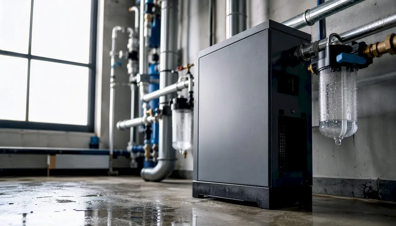
For most industrial operations in the Czech Republic, a condensation (refrigerated) dryer is the standard and most economical choice. Choose an adsorption dryer when the application requires a pressure dew point below 0 °C. Membrane dryers cover specific cases with low flow and a requirement for zero electrical energy consumption.
A brief overview of the three main technologies:
- Condensation dryer: cools the air, separates and discharges the condensate; achieves a pressure dew point of approximately +3 °C; low acquisition and operating costs.
- Adsorption dryer: air passes through an adsorbent (silica gel, activated alumina or molecular sieves); achieves a PDP of up to −40 °C or −70 °C; higher energy consumption.
- Membrane dryer: moisture passes through a membrane; does not require electrical power supply; the typical achievable PDP is between +3 °C and −40 °C depending on the specific design and operating conditions; limited to lower flow rates.
Basic rule for selection: first determine the required pressure dew point, then select the technology. Size the dryer's flow rate with a reserve of 10–20% above the compressor's nominal output, while always recalculating the nominal output using correction factors for pressure and temperature.
Contents
- What types of air dryers for compressors exist?
- What is pressure dew point and which values should you choose?
- How to size a dryer: procedure with correction factors
- Energy efficiency and life cycle costs of dryers
- How to properly maintain a dryer and integrate it into the air distribution system
- What to watch out for when choosing a dryer and how to prepare an inquiry
- How we choose solutions at Kompresory-vzduchotechnika
- Key takeaways
- Dryers and accessories for your compressor from Kompresory-vzduchotechnika
- Useful resources and technical data sheets
- Frequently asked questions
What types of air dryers for compressors are there?
Refrigerant (chilled) dryers
A refrigerant dryer cools the compressed air below the dew point temperature, forcing moisture to condense. The condensate collects in a separator and is automatically drained. A typical achievable pressure dew point is approximately +3 °C, which is sufficient for the vast majority of industrial applications.
Advantages: low purchase cost, simple operation, low energy consumption, minimal maintenance requirements.
Disadvantages: PDP cannot be reduced below 0 °C (risk of condensate freezing inside the dryer), unsuitable for applications with extreme air dryness requirements.
Refrigerant dryers are divided into non-cycling (the refrigeration circuit compressor runs continuously) and cycling types (the compressor switches on as needed). Cycling variants save energy under partial load.
Typical use: workshops, auto repair shops, production lines, pneumatic tools, general industrial production.
Membrane dryers
A membrane dryer uses a selectively permeable membrane: water molecules pass through the membrane wall outward, while dry air continues onward. It requires no electrical power or moving parts.
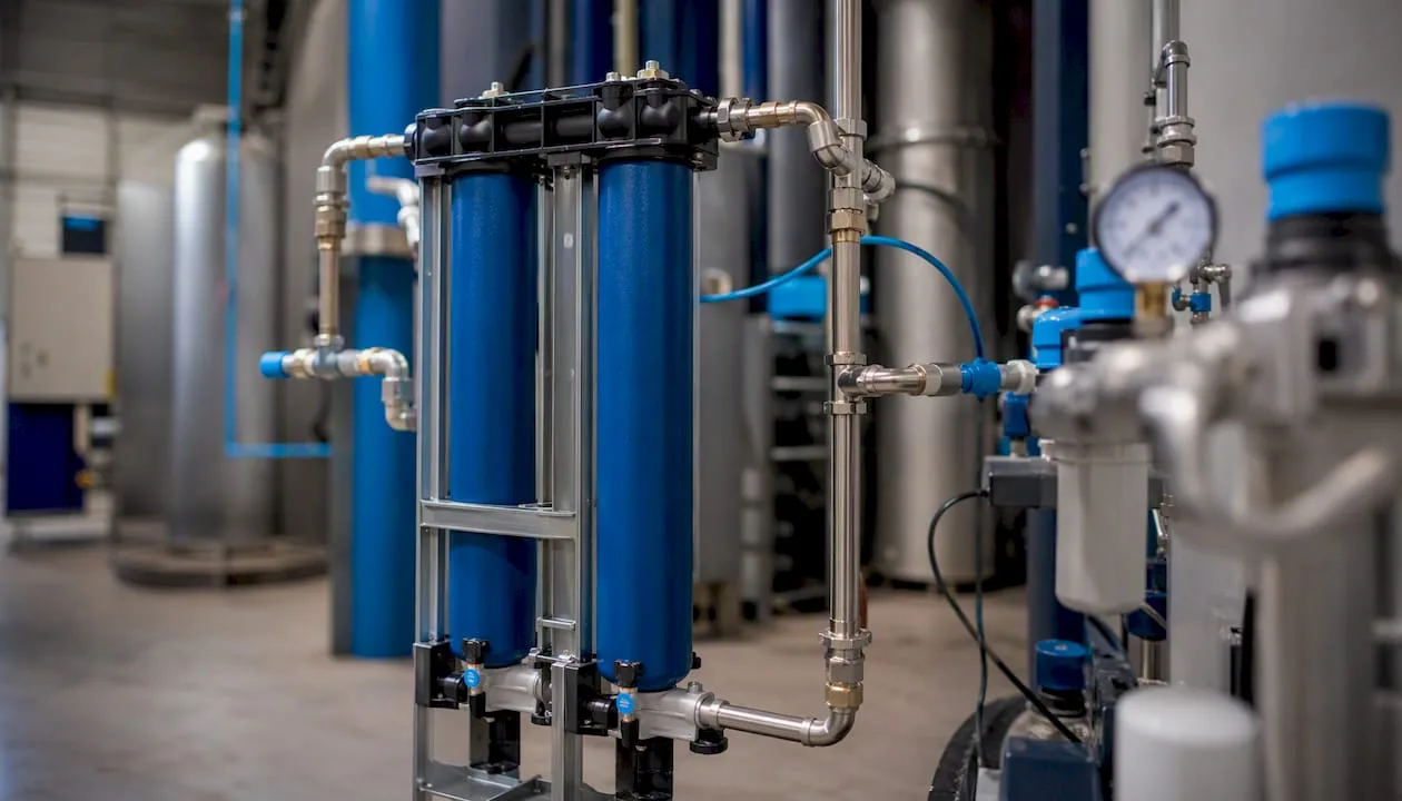
Advantages: no electricity consumption, compact dimensions, zero maintenance of moving parts, suitable for explosive environments.
Disadvantages: limited flow capacity, typically achieves PDP between condensation and adsorption values (usually in the range of +3 °C to −40 °C), the achievable PDP depends on flow and pressure, higher price per unit of flow.
Typical use: analytical instruments, small industrial applications, mobile equipment, environments with explosion risk.
Combined systems
Combining a refrigerant dryer and an adsorption dryer makes sense when the required PDP is very low but the operation generates large flow rates. The refrigerant stage removes most of the moisture and reduces the load on the adsorption stage, thereby extending the adsorbent's service life and reducing overall energy consumption.
Professional tip: When selecting an adsorption dryer, always verify whether the manufacturer states the PDP at rated flow and reference conditions. A PDP of −40 °C achieved at 50% flow does not mean the dryer will meet this parameter at full load.
What is the pressure dew point and which values should you choose?
Pressure dew point (PDP) is the temperature at which air begins to condense at a given operating pressure. If the PDP is +3 °C and the air in the piping cools to +2 °C, condensate will form. In unheated spaces or outdoor distribution systems, there is a risk of freezing when the PDP is above 0 °C.
The relationship to the ISO 8573-1 standard is direct: this standard defines compressed air quality classes based on the content of solid particles, water, and oil. Class 4 corresponds to a PDP of +3 °C (refrigerant dryer), class 2 corresponds to a PDP of −40 °C (adsorption dryer). When specifying a system, always state the required ISO 8573-1 class, not just a verbal description.
| Application | Recommended PDP | ISO 8573-1 Class (water) | Suitable dryer type |
|---|---|---|---|
| General workshop, pneumatic tools | +3 °C | Class 4 | Refrigerant |
| Car service, assembly line | +3 °C | Class 4 | Refrigerant |
| Paint shop (standard) | 0 to −10 °C | Class 3 | Refrigerant or adsorption |
| Paint shop (high requirements) | −20 °C | Class 2–3 | Adsorption |
| Food industry, beverage industry | −20 °C | Class 2 | Adsorption |
| Pharmaceuticals, laboratory equipment | −40 °C | Class 1–2 | Adsorption |
| Electronics manufacturing, clean rooms | −40 to −70 °C | Class 1 | Adsorption |
How to size a dryer: procedure with correction factors
Manufacturers state the nominal capacity of a dryer for reference conditions, usually 25 °C ambient temperature, 35 °C inlet air temperature and 7 bar operating pressure. Under different operating conditions, the nominal capacity must be recalculated, otherwise there is a risk of undersizing and failing to achieve the required PDP.
Correction factors: reference tables
Correction according to operating pressure:
| Operating pressure (bar) | Pressure correction factor |
|---|---|
| 8 bar | 1,08 |
Correction according to inlet air temperature:
| Inlet air temperature | Temperature correction factor |
|---|---|
| 40 °C | 0,84 |
Calculation example
The compressor delivers 80 m³/h at an operating pressure of 8 bar. The inlet air to the dryer has a temperature of 40 °C (typical summer in an unventilated compressor room). The correction factor for 8 bar is 1.08; the correction factor for 40 °C is 0.84.
The actual required dryer capacity = 80 ÷ (1.08 × 0.84) = 80 ÷ 0.907 = approximately 88 m³/h.
With a 15% reserve, the minimum nominal capacity of the dryer is 101 m³/h. The Remeza RFD81 model with a nominal capacity of 81 m³/h would not be sufficient in this case; a higher model needs to be selected. Detailed factors for selecting an industrial compressor are described in the guide on the Kompresory-vzduchotechnika website.
Energy efficiency and life cycle costs of dryers
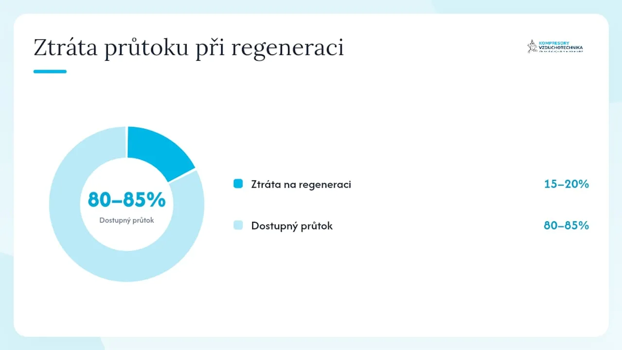
The purchase price of a dryer is only part of the total costs. For refrigerant dryers, the electricity consumption of the refrigeration compressor typically forms the largest operating cost item. For adsorption dryers with heatless regeneration, it is the loss of compressed air for regeneration, which can reach 15–20% of the total flow.
Key factors affecting the total cost of ownership (TCO):
- Availability of spare parts: — Atlas Copco and Kaeser maintain service networks in the Czech Republic with availability of original parts; when selecting a less known brand, verify the availability of service.
Practical estimate: a refrigerant dryer with a power input of 1 kW operating continuously (8,760 hours/year) will consume approximately 8,760 kWh per year. At the average price of industrial electricity in the Czech Republic, this represents a significant item that, over a 10-year service life, can exceed the purchase price of the dryer several times over. An adsorption dryer with heatless regeneration and a flow rate of 100 m³/h will lose 15–20 m³/h of compressed air for regeneration, which the compressor must supply additionally.
TCO summary: Always compare the total costs over 5–10 years, not just the purchase price. For adsorption dryers with high flow rates, the version with heating or heat recovery typically pays for itself within 2–3 years.
How to properly maintain a dryer and integrate it into the air distribution system
Recommended order of components in the air treatment station
Correct connection of the dryer into the distribution system is just as important as its selection. Recommended order: compressor, air tank (accumulation and pre-cooling), oil and condensate separator, dryer, fine filtration, consumers. An air tank placed before the dryer reduces temperature peaks and flow pulsations, thereby protecting the dryer from overload. Detailed requirements for the layout of the compressor room are described in the guide to basic compressor room requirements.
Service requirements by dryer type
Refrigerant dryers:
- Cleaning or replacing the inlet filter (typically every 3–6 months).
- Checking and cleaning the condenser (air-cooled or water-cooled).
- Checking the function of the automatic condensate drain.
Adsorption dryers:
- Replacing the adsorbent as recommended by the manufacturer (typically every 2–4 years, depending on inlet air quality).
- Replacing pre-filters and after-filters (every 3–12 months).
- Checking the tower switching valves.
Membrane dryers:
- Replacing the pre-filter (condensate reaching the membrane will damage it).
- Visual inspection of the membrane.
Condensate drainage
Automatic float or electronic condensate drains are more reliable than manual ones. Electronic timer drains are inexpensive, but they also discharge some compressed air. Float drains discharge condensate continuously without air loss, but require regular checks of patency.
Professional tip: When starting operation after a longer shutdown or in the morning in winter, water hammer can occur if condensate has accumulated in the piping. Before starting the appliances, let the compressor run for 5–10 minutes with the manual drain open at the lowest point of the distribution system.
What to watch out for when selecting a dryer and how to prepare an inquiry
Mapping applications to dryer type
Different industries have different requirements for PDP and flow. A workshop or car service can manage with a refrigerant dryer and a PDP of +3 °C. A paint shop with high demands on surface quality needs a PDP of −20 °C or lower. The food and pharmaceutical industries require an adsorption solution with a PDP of −40 °C and compliance with ISO 8573-1 class 1 or 2. Electronics manufacturing and clean rooms typically work with a PDP of −40 to −70 °C. The overview of examples of compressor use for workshops and production offers further mapping of technologies by field.
Checklist of parameters for an inquiry
Before sending an inquiry to a supplier, have the following values ready:
- Nominal compressor flow (m³/h or l/min) and actual operating pressure (bar).
- Inlet air temperature into the dryer (°C) and ambient temperature at the installation site.
- Required pressure dew point (PDP) and the corresponding ISO 8573-1 class.
- Available electrical power input (kW, phases) and space for installation (dimensions, orientation).
- Condensate drainage method (sewerage, collection tank, disposal regulations).
- Requirements for a service contract and availability of spare parts.
- Whether PDP measurement is required after installation.
Questions for the supplier
When selecting a supplier, ask specifically:
- Does it provide correction tables for pressure and temperature for the given model?
- What are the service intervals and prices of spare parts (adsorbent, filters)?
- Does it offer measurement of the actual PDP after installation?
- What is the availability of service intervention in the Czech Republic (response time, distance to service)?
How to submit an inquiry step by step
- Fill in the parameter checklist above.
- Recalculate the flow rate using correction factors (see the sizing section).
- Add a 10–20% margin to the resulting capacity.
- Specify the required ISO 8573-1 class (not just a verbal description).
- Attach a wiring diagram or a description of the compressor room.
- Request a technical data sheet with reference conditions and correction factors.
The practical compressor accessories checklist will help you check whether you have forgotten the air tank, filters, or oil separator.
How we choose solutions at Kompresory-vzduchotechnika
Kompresory-vzduchotechnika offers technical consultations, custom sizing, and service for the entire compressed air treatment system. The approach to selecting a dryer is based on the customer's specific operating data, not on catalog values.
The standard procedure for designing a solution includes:
- Determining the actual flow rate and pressure in operation (measurement or calculation from the compressor parameters).
- Verifying the inlet air temperature and ambient conditions in the compressor room.
- Calculating the actual required dryer capacity using correction factors.
- Recommendation of a specific model with a technical data sheet and reference conditions.
- Offer of installation, condensate drain connection, and verification PDP measurement after startup.
For applications requiring PDP below 0 °C, Kompresory-vzduchotechnika recommends an adsorption solution and will also assess whether a combination of a refrigeration dryer and an adsorption dryer could result in a lower TCO. Spare parts support and service are available to customers throughout the Czech Republic.
The internal guide compressed air drying and condensate removal contains practical recommendations, an overview of product ranges, and links to technical data sheets for the most commonly supplied models.
A technical consultation or inquiry can be submitted directly via the Kompresory-vzduchotechnika website.
Key takeaways
The correct selection of an air dryer depends on three parameters: the required pressure dew point, the actual flow rate converted using correction factors, and the total life cycle costs.
| Point | Details |
|---|---|
| Refrigeration dryer for standard operation | Achieves a PDP of approximately +3 °C; suitable for workshops, car repair shops, and general production. |
| Adsorption dryer for critical applications | Achieves PDP down to very low sub-zero values; necessary for paint shops with high demands, pharmaceuticals and electronics. |
| Correction factors are mandatory | The nominal output of the dryer applies to reference conditions (7 bar, 35°C inlet); recalculate for different conditions. |
| Reserve of 10–20% on capacity | Always size the dryer with a reserve above the recalculated compressor flow rate. |
| Kompresory-vzduchotechnika | Offers custom sizing, installation and PDP measurement after installation for facilities throughout the Czech Republic. |
Personal note on dryer selection
The most common mistake I see when selecting a dryer is not choosing the wrong technology. It's ignoring the correction factors. The customer selects a dryer based on the compressor's nominal flow rate, but forgets that in an unventilated compressor room in summer, the inlet air temperature can reach 45°C. At 45°C, the actual capacity of a refrigerant dryer drops to approximately 68% of the nominal value. The dryer then can't keep up, PDP rises, and condensate ends up in the distribution system exactly where you don't want it.
The second thing that's underestimated: the TCO of adsorption dryers with heatless regeneration. A loss of 15–20% of compressed air for regeneration means the compressor has to work permanently at a higher output. For larger flow rates, the heated or heat-recovery version pays for itself quickly. The figures from the technical data sheet are available; you just need to compare them.
Dryers and accessories for your compressor from Kompresory-vzduchotechnika
Kompresory-vzduchotechnika supplies refrigerant and adsorption air dryers, treatment units and condensate drainage accessories. The offering covers facilities from small workshops to industrial lines with high flow rates.
The product range includes compressed air treatment units for standard applications up to 10 bar, as well as metal treatment units up to 18 bar for more demanding operations. The range also includes pneumatic components and accessories for complete assembly of a treatment station.
Technical consultation is available for every order: capacity recalculation of the dryer according to correction factors, recommendation of a specific model, and support during installation. Please send your technical inquiry or sizing question via the contact form on the Kompresory-vzduchotechnika website.
Useful resources and technical data sheets
To verify specifications and prepare an inquiry, we recommend working directly with the manufacturers' technical data sheets. Look for the following information in the datasheet:
- Pressure dew point (PDP): under which reference conditions it is stated.
- Nominal flow rate (m³/h or l/min): and the corresponding reference pressure and temperatures.
- Correction tables: for inlet air pressure and temperature.
- Service intervals: replacement of filters, adsorbent, cooling medium.
- ISO 8573-1 class: which the model meets under rated conditions.
Relevant resources and internal guides:
- Compressed air drying and condensate removal — practical recommendations and a product overview from Kompresory-vzduchotechnika.
- Factors for selecting an industrial compressor: 2026 guide — sizing and correction factors for the entire system.
- Technical datasheets from Atlas Copco and Kaeser are available on their official websites; always verify that the datasheet corresponds to the specific model and series.
- Standard ČSN EN ISO 8573-1 defines compressed air quality classes; available through the Czech Agency for Standardization (ČAS).
Frequently Asked Questions
What type of dryer is suitable for a typical workshop or auto repair shop?
For a workshop or auto repair shop, a refrigerant dryer with a pressure dew point of approximately +3 °C is sufficient. Size it with a margin above the compressor's flow rate and recalculate the capacity using correction factors for operating pressure and temperature.
What is the difference between a refrigeration and a desiccant dryer?
A refrigerant dryer cools the air and separates condensate; it achieves a PDP of approximately +3 °C and has low energy consumption. An adsorption dryer passes air through an adsorbent and achieves very low sub-zero PDP values; it is more energy-intensive but necessary for applications with critical dryness requirements.
What should you watch out for when selecting a dryer for a compressor?
The most important thing is to recalculate the dryer's nominal capacity using correction factors for the actual operating pressure and inlet air temperature. Nominal values apply to reference conditions; at different temperatures or pressures, the actual capacity differs.
What is compressor intake capacity and how does it affect dryer selection?
Compressor intake capacity (flow rate) indicates the amount of air the compressor draws in and compresses per unit of time, usually in m³/h or l/min. The dryer must have a capacity equal to or greater than this flow rate after recalculation using correction factors; an undersized dryer will not achieve the required PDP.
How often does air dryer maintenance need to be performed?
For refrigerant dryers, the inlet filter is cleaned or replaced every 3–6 months, and the function of the automatic condensate drain is checked regularly. For adsorption dryers, the adsorbent is typically replaced every 2–4 years depending on the quality of the inlet air, and pre-filters every 3–12 months.
Recommended
- Checklist of accessories for compressors: a guide for technicians - Kompresory-Vzduchotechnika.cz
- List of the best compressors 2026: a buying guide - Kompresory-Vzduchotechnika.cz
- Comparison of screw and piston compressors: a selection guide - Kompresory-Vzduchotechnika.cz
- Factors for selecting an industrial compressor: a 2026 guide - Kompresory-Vzduchotechnika.cz

Overview of Compressor Noise Reduction Methods for Technicians

In brief:
- The fastest way to reduce compressor noise is by replacing the intake filter, adding anti-vibration pads, and installing an intake silencer.
- Correctly identifying the source of noise is key to effective reduction, with the main sources being intake, exhaust, mechanics, and vibration.
The fastest and most reliable way to reduce compressor noise is through three steps: immediately replacing the intake filter, installing anti-vibration pads under the machine, and fitting an intake silencer. These measures can be carried out within a single shift, require no specialized tools, and deliver measurable results. Medium-term steps, such as acoustic enclosures and pipe silencers, should be planned over days to weeks. Investment decisions, such as switching to a screw compressor with VSD drive, should be considered when the existing machine no longer meets operational or safety requirements.
Quick steps for immediate effect:
- Check and replace the intake filter. A clogged filter increases intake vacuum, changes the frequency characteristics of the noise, and accelerates component wear.
- Top up or replace the lubricant in the bearings. Insufficient lubrication is one of the most common causes of mechanical noise.
- Tighten all mounting bolts and fasteners. Loose parts resonate and amplify transmitted noise.
- Place the compressor on rubber anti-vibration pads or silent blocks.
- Check the flexible couplings between the compressor and the piping.
When to call a specialist: If damaged bearings are suspected (metallic squealing, uneven running), in case of resonance affecting the entire structure or floor, and when a soundproof enclosure with controlled ventilation is required.
Professional tip: Before making any intervention, measure the baseline noise level with a sound level meter. Without a baseline value, it is not possible to objectively verify whether the measure is effective.
Contents
- What are the main sources of compressor noise and how to quickly identify them?
- How to measure noise levels in the workplace and what are the reference values for compressors?
- What immediate measures can be taken during a single shift?
- How to design an acoustic enclosure or cabin for a compressor?
- Which intake and exhaust silencers to choose and how do they affect back pressure?
- How to properly isolate vibrations and select silent blocks?
- How to choose compressor technology with regard to noise level?
- How to proceed with implementation: from diagnostics to result verification?
- Key takeaways
- Expert note from practice
- Frequently asked questions
What are the main sources of noise in a compressor and how can they be quickly identified?
Compressor noise originates from four basic sources: intake, exhaust, mechanical parts, and vibrations transmitted through the structure. Correct identification of the source determines which measure to apply first.
Overview of noise sources:
- Intake: Pulsating airflow into the compressor generates low-frequency noise. A clogged filter makes the situation worse.
- Exhaust and pulsation: The discharge side produces pressure pulses, especially in piston compressors.
- Mechanical parts: Bearings, gears, and the piston mechanism produce noise when worn or inadequately lubricated.
- Motor: The electric motor adds electromagnetic and ventilation noise.
- Piping and airflow: Sharp bends, constrictions, and unsuitable pipe lengths cause aerodynamic noise and resonance.
- Structure-borne vibration: The compressor transmits vibrations through the frame, floor, and fixed piping throughout the entire building.
Distinguishing between airborne noise and structure-borne noise is crucial, as each type requires a different measure. Use sound insulation (enclosures, panels) against airborne noise. Anti-vibration elements address structure-borne noise.
Quick identification procedure:
- Place your hand (or a vibration meter) on the frame and piping while running. Strong vibrations in the frame indicate structural transmission.
- Temporarily disconnect the intake filter and compare the noise. A significant change confirms intake as the dominant source.
- Check the exhaust side and the air tank. Metallic knocking or hissing indicates exhaust pulsations or leaks.
- Listen to the bearings while idling without load. Squeaking or an irregular sound indicates mechanical wear.
Professional tip: If the noise sounds different under loaded and unloaded operation, it is predominantly an aerodynamic or exhaust source. If the character does not change, look for a mechanical or vibration origin.
How to measure the noise level in the workplace and what are the approximate values for compressors?
Measuring noise before and after an intervention is a prerequisite for verifying the effect of the measures taken. Without documented values, it is not possible to prove improvement or compliance with occupational health and safety requirements.
Approximate noise levels by compressor type
| Compressor type | Approximate noise level |
|---|---|
| Piston compressor (standard) | 75–85 dB(A) |
| Screw compressor | 65–75 dB(A) |
| Quiet/oil-free model (scroll, special) | 60–70 dB(A) |
These values are indicative and depend on the output, age of the machine, and installation conditions. A more detailed overview of the impact of noise on the working environment is provided in the article on quiet compressor operation.
Step-by-step measurement procedure
- Use a calibrated class 2 sound level meter or higher. Mobile apps are indicative only, not sufficient for occupational health and safety documentation.
- Position the microphone at a height of 1.5 m above the floor, 1 m from the surface of the compressor.
- Perform the measurement at full load, at idle, and at startup.
- Record the values from four sides of the machine and calculate the average.
- Repeat the measurement after each intervention and document the results.
Safety notice: In case of continuous exposure above 80 dB(A), the use of personal hearing protection equipment is mandatory. Above 85 dB(A), the employer must implement a hearing protection program and record employee exposure in accordance with Government Regulation No. 272/2011 Coll. An overview of noise reduction methods in the context of occupational health and safety can also be found in the article on noise reduction in operation.
What immediate measures can be taken during a single shift?
Most low-cost measures do not require shutting down the machine for more than one hour. Below, the steps are ordered according to their typical impact on noise level.
Shift checklist:
- Check and replace the intake filter. A clogged filter changes the noise characteristics and increases component stress.
- Top up lubricant in bearings and gears according to the service schedule.
- Tighten all mounting bolts, clamps, and pipe fastenings.
- Check the condition of the rubber pads under the compressor. Hardened or cracked pads stop dampening vibrations.
- Install flexible couplings (compensators) between the compressor and the fixed piping.
- Remove or replace sharp elbows in the piping with large-radius bend fittings.
- Check the air tank and piping for leaks. Hissing indicates air is escaping and adding to the noise.
Proper compressed air filtration protects the compressor as well as the downstream equipment, while also contributing to more stable and quieter operation.
Order of interventions by priority
- Replacement of the intake filter (immediate effect, low cost).
- Checking the lubrication and topping up the oil.
- Tightening fasteners and removing loose parts.
- Installing anti-vibration pads or silent blocks.
- Fitting flexible couplings on the discharge piping.
Professional tip: After each intervention, measure the noise level and record the result. If a given step did not produce a measurable change, move on to the next one. This way you can quickly identify the dominant noise source and avoid wasting effort on secondary causes.
How to design an acoustic enclosure or cabin for a compressor?
An acoustic enclosure can reduce the noise level by 10–20 dB(A), but only if it is designed correctly. The most common mistake is neglecting ventilation, which leads to overheating and machine failures.
Principles of acoustic enclosure design:
- Combine sound absorption (mineral wool, acoustic foam) with a rigid insulating shell (steel sheet, sandwich panel).
- Provide access doors or removable panels for servicing. An enclosure without access makes maintenance impossible.
- Fit every cooling opening with flow silencers (baffle-type or absorption silencers) so they do not cancel out the acoustic effect of the enclosure.
- Size the ventilation openings so that the temperature inside the enclosure does not exceed the compressor's operating limit.
- Line the interior surfaces with absorbent material to reduce reflections.
- Seal pipe grommets acoustically, not just mechanically.
Detailed requirements for compressor room design, including ventilation and noise reduction, are summarized in the guide to basic compressor room requirements.
Checklist for the designer:
- Access doors with acoustic sealing
- Silencers on both the intake and exhaust openings of the enclosure
- Heat dissipation with controlled air flow
- Interior absorbent lining on all surfaces
- Acoustically sealed grommets for piping and cabling
- Temperature sensor with alarm in case of overheating
Professional tip: Integrate ventilation into the design from the start, not as an afterthought. Openings added later without silencers will cancel out most of the acoustic effect of the enclosure.
Which intake and exhaust silencers to choose and how do they affect back pressure?
Silencers are the most effective measure against medium- and high-frequency noise on intake and exhaust piping. Each type works on a different principle and is suitable for a different frequency range.
Types of silencers and their application:
- Resistive (absorption) silencers: Absorb sound using porous material. Effective for medium and high frequencies, low pressure drop.
- Reactive (impedance) silencers: Work on the principle of wave reflection and interference. Suitable for low frequencies and exhaust pulsations.
- Combined (impedance mix): Combine both principles, wider frequency coverage.
- Microperforated silencers: Thin perforated plates without absorption material. Suitable where fibrous material cannot be used (clean operations).
Comparison of silencer types
| Silencer type | Main advantage | Disadvantage |
|---|---|---|
| Absorption (resistive) | Low pressure drop, easy installation | Less effective for low frequencies |
| Reactive (impedance) | Effective for low frequencies and pulsations | Higher pressure loss, larger dimensions |
| Combined | Wider frequency coverage | Higher cost, more complex design |
| Microperforated | Suitable for clean operations | Lower overall efficiency |
Back pressure is a key trade-off: every silencer increases resistance in the piping. When sizing, select a silencer with pressure losses up to 0.5% of the compressor's operating pressure, otherwise output decreases and energy consumption increases.
Installation principles: Place the silencer as close as possible to the noise source. Avoid resonant pipe lengths (lengths corresponding to a quarter of the wavelength of the dominant frequency). Flexible couplings before and after the silencer prevent the transmission of vibrations into the piping.
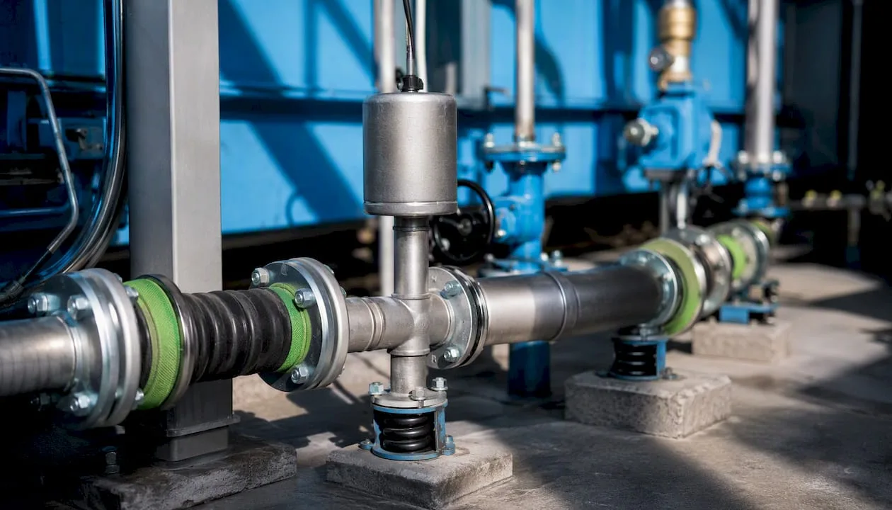
How to properly isolate vibrations and select silent blocks?
Vibrations transmitted through the structure are the second most common source of noise in compressor rooms. Rigidly connected piping and frames act as acoustic bridges and spread noise throughout the building.
Types of anti-vibration solutions:
- Rubber pads: The simplest and cheapest solution for smaller compressors. Suitable for frequencies above 20 Hz.
- Spring mounts: More effective for heavier machines and low vibration frequencies. Allow precise stiffness adjustment.
- Flexible couplings and corrugated hoses: Interrupt the transmission of vibrations from the compressor to the fixed piping. A mandatory part of every installation.
- Flexible pipe hangers: Prevent the transmission of vibrations from the piping to the ceiling or wall structure.
Sizing of the silent block depends on the weight of the machine and the frequency of the dominant vibrations. A silent block that is too stiff does not flex, while one that is too soft causes instability. Manufacturers state the load capacity and frequency range in the technical data sheet.
Diagnostic checklist for installation:
- Are all four (or more) pads evenly loaded? Check the alignment of the machine.
- Are flexible couplings fitted on both the discharge and suction piping?
- Is the piping suspended on flexible hangers, not rigidly bolted to the wall?
- Are thermal expansions of the piping compensated?
- Are there no rigid contacts between the compressor and the surrounding structure (bolts, pipes, cables routed without grommets)?
Professional tip: The most common acoustic bridge occurs where the installer firmly bolts the piping to the wall right after the flexible coupling. The flexible coupling then has no effect. The piping must be suspended on flexible hangers along its entire length, not just at the point of connection to the compressor.
How to choose a compressor technology with regard to noise level?
The choice of technology is the most important decision when planning a new installation or replacing an existing machine. Noise level is one of the key parameters alongside output, pressure, and operating costs.
Comparison of technologies by noise level:
- Piston compressors: Highest noise level, typically 75–85 dB(A). Suitable for intermittent operation and lower outputs. For continuous operation in enclosed spaces, noise insulation is required.
- Screw compressors: Medium noise level, 65–75 dB(A). Suitable for continuous operation. Lower exhaust pulsation compared to piston compressors.
- Scroll compressors and special quiet models: Lowest noise level, 60–70 dB(A). Suitable for sensitive environments (laboratories, healthcare, offices). Higher purchase price.
- VSD (variable speed drive): Reduces motor speed at lower air demand. The result is lower noise at partial load and lower energy consumption. In operations with variable load, a VSD compressor can eliminate the need for a separate soundproofed compressor room.
Practical parameters for selecting an industrial compressor, including noise level, are summarized in the guide to selecting an industrial compressor.
When to invest in new technology instead of soundproofing the existing machine:
- The existing compressor is older than 10 years and requires frequent repairs.
- The operating profile has changed to continuous or variable load.
- The noise level of the existing machine exceeds 80 dB(A) even after all measures have been implemented.
- The costs of noise reduction exceed 30–40% of the value of a new machine.
How to proceed with implementation: from diagnostics to verification of results?
A systematic approach shortens the implementation time and prevents wasting resources on measures that will not produce an effect.
Implementation phases
- Preparation and measurement (hours): Measure the baseline noise level from four sides of the machine under full load. Identify the dominant source (intake, exhaust, mechanics, vibration). Document the results.
- Quick interventions (hours to 1 day): Filter replacement, lubricant top-up, fastening tightening, installation of anti-vibration pads and flexible couplings. Estimated costs: low (hundreds to low thousands CZK).
- Medium-term measures (days to 2 weeks): Installation of intake and exhaust silencers, piping route adjustments, installation of flexible hangers. Estimated costs: medium (thousands to tens of thousands CZK).
- Long-term investments (weeks to months): Construction of an acoustic enclosure or cabin, transition to quieter technology (VSD, screw or scroll compressor). Estimated costs: higher (tens to hundreds of thousands CZK).
Checklist for verifying the effect:
- Measure the noise level after each phase, from the same locations as in the baseline measurement.
- Compare the values before and after. A successful measure will result in a measurable decrease.
- Document each intervention: date, description, measured values.
- If the noise does not decrease after quick interventions, proceed to medium-term measures without delay.
- An integrated solution in the compressor room design (absorption, isolation, pipe insulation) reduces overall costs and increases efficiency compared to gradual, separate interventions.
When to contact Kompresory-vzduchotechnika service: If damaged bearings or serious mechanical faults are suspected, when a design for an acoustic enclosure with controlled ventilation is needed, when selecting new technology, or when noise measurement and documentation for occupational health and safety purposes is required. The Kompresory-vzduchotechnika team provides technical consulting, service interventions, and turnkey solution designs.
Key findings
The fastest and most reliable reduction of compressor noise is achieved by combining immediate maintenance, anti-vibration mounting, and intake silencers, with each measure verified by measurement before and after the intervention.
| Item | Details |
|---|---|
| Immediate measures | Filter replacement, lubrication, and tightening of fasteners can be carried out during a single shift with minimal costs. |
| Anti-vibration mounting | Silent blocks and flexible couplings interrupt the transmission of vibrations into the structure and piping. |
| Intake and exhaust silencers | Absorption silencers reduce mid- and high-frequency noise with low pressure loss. |
| Acoustic enclosure | A properly designed enclosure with ventilation silencers will reduce the noise level by 10–20 dB(A). |
| Technology selection | VSD and screw compressors achieve 65–75 dB(A), quiet models and scroll compressors 60–70 dB(A). |
Expert note from practice
Technicians in operation most often focus on the acoustic enclosure as the first solution, because it is visible and appears comprehensive. However, practice shows that an enclosure built over a machine with loose bolts, hardened washers, and a clogged filter will deliver only a fraction of the expected effect. The noise simply travels further through the piping into the building.
The correct order is the opposite: first eliminate the causes of noise at the source, then isolate what remains. This approach is cheaper and the results are more lasting. Investing in an enclosure only makes sense once the machine is running in good technical condition and the remaining noise comes from the compressor's inherent design characteristics that cannot be eliminated.
One thing technicians regularly overlook: piping bolted firmly to the wall right after the flexible coupling. The coupling then serves no function and the vibrations continue to propagate further. Switching to flexible hangers along the entire length of the piping is enough, and the result is immediate.
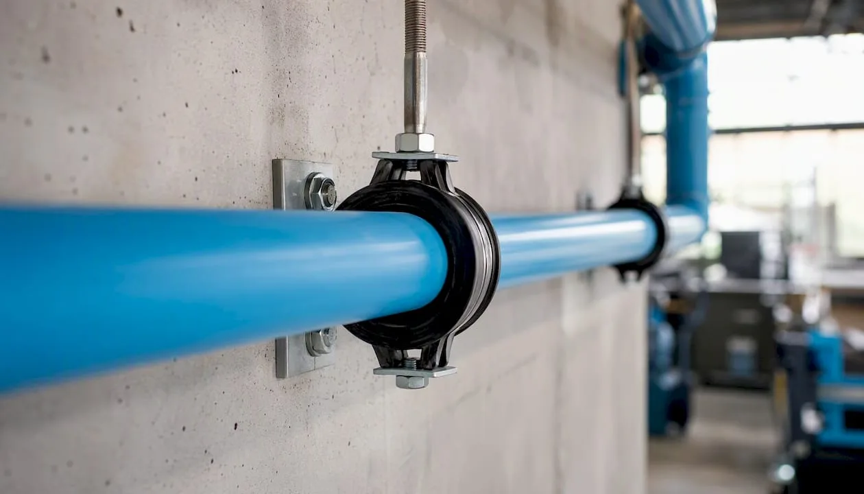
Frequently Asked Questions
How to soundproof a compressor yourself?
Start by replacing the intake filter, topping up lubricant, and installing rubber anti-vibration pads under the machine. Add flexible couplings to the discharge piping. These measures can be carried out during a single shift without specialized tools.
How many dB does 40 dB(A) correspond to in practice?
A level of 40 dB(A) corresponds to a quiet office or a calm living room. A standard piston compressor reaches 75–85 dB(A), a screw compressor 65–75 dB(A), and quiet models 60–70 dB(A).
How does a scroll compressor work and why is it quieter?
A scroll compressor compresses air using two spiral elements without pistons or valves. The result is smooth, pulsation-free compression with a noise level typically of 60–70 dB(A), which is significantly lower than with piston machines.
How to regulate compressor pressure to reduce noise?
A lower operating pressure means lower load on the machine and lower noise. Set the pressure to the lowest value that still meets the application requirements. VSD drive also automatically adjusts the speed to current demand, which reduces noise under partial load.
When is it necessary to call in a noise measurement specialist?
Professional measurement is necessary when employees are continuously exposed to levels above 80 dB(A), for occupational health and safety documentation, and when designing an acoustic enclosure or compressor room. Kompresory-vzduchotechnika provides technical consulting and measurement as part of its service offerings.
Recommended
- Compressor bleeding procedure: a guide for technicians - Kompresory-Vzduchotechnika.cz
- Noise Reduction in Operation: Methods, Standards and Health Protection - Kompresory-Vzduchotechnika.cz
- Definition of the compressor duty cycle: a guide for technicians - Kompresory-Vzduchotechnika.cz
- The importance of compressor diagnostics for efficient operation - Kompresory-Vzduchotechnika.cz


Oil-lubricated compressor for workshops and industrial use: how to choose
We have merged this article with a more detailed and more up-to-date guide on the same topic. Continue here: How to choose the right oil for a compressor: a guide 2026.


The Role of Air Receivers: A Guide for Technicians
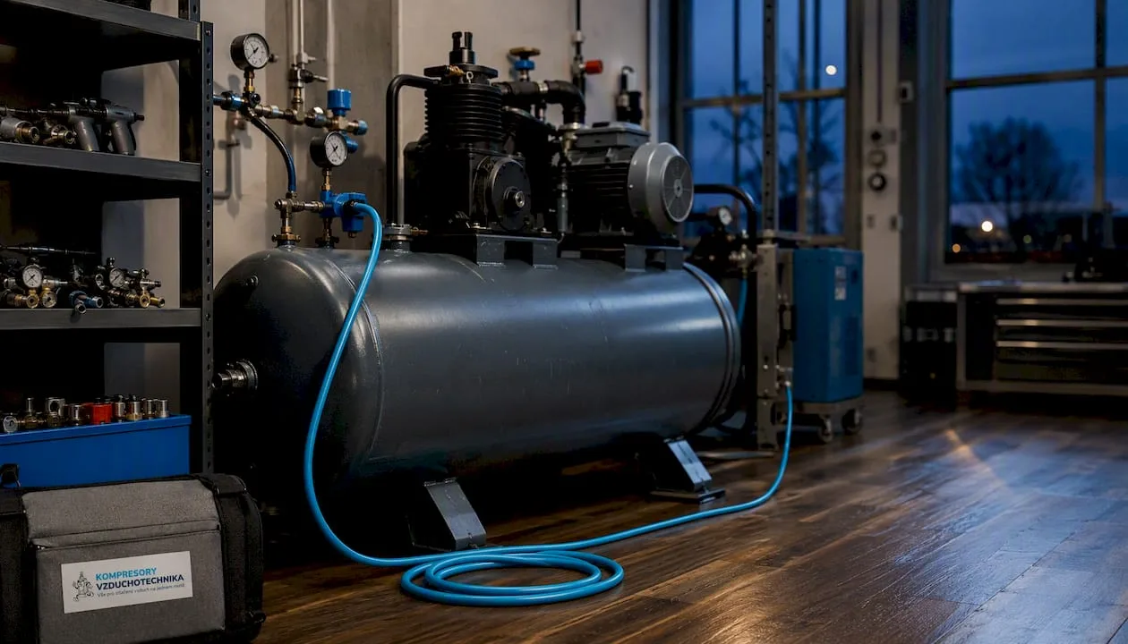
An air receiver is a buffering and accumulation element of the compressed air system that stabilizes the pressure in the distribution network, covers short-term consumption peaks, and reduces the number of compressor switching cycles. A properly sized air receiver protects the compressor from excessive wear, relieves the dryer, and improves the quality of the delivered air. The key parameters for the decision are the pressure range, the required flow rate, and the supply time in minutes. Before commissioning, check the sizing of the air receiver and its connection to the dryer.
- Main functions: pressure equalization, accumulation for peak consumption, reduction of switching cycles
- Key metrics: pressure range (bar), flow rate (l/s or m³/min), supply time (min)
- Recommendation: verify the sizing and the order of equipment in the piping (compressor → air receiver → dryer, or compressor → dryer → air receiver, depending on the type)
Contents
- How does the air receiver work within the compressor circuit?
- What are the main functions and benefits of an air receiver?
- How to size an air receiver?
- What types of air receivers are available?
- How to properly install and position the air receiver?
- How to maintain the air receiver and ensure its safe operation?
- How does the air receiver affect operating costs?
- Kompresory-vzduchotechnika will help you with the selection and servicing of the air receiver
- Key insights
- The air receiver that technicians underestimate
- Useful resources and further reading
- Frequently asked questions
How does the air receiver work within the compressor circuit?
Air enters the air receiver from the compressor's discharge piping under pressure. Inside the tank, the air settles, slows down and begins to cool. This way, the air receiver functions as a secondary heat exchanger: moisture contained in the air condenses on the tank walls and flows down to the bottom, where it is removed by the drain valve.

The output from the air receiver leads to the distribution system or directly to the dryer. The air receiver thus smooths out pressure pulses caused by the compressor's duty cycle and maintains a stable output pressure. The compressor's control system responds to the pressure in the air receiver via a pressure switch or regulator.
Main components of the air receiver and their functions:
- Inlet/outlet flange: connection to the compressor and distribution piping
- Drain valve (drain cock or automatic drain): removal of condensate from the bottom of the tank
- Pressure gauge: monitoring the current pressure in the tank
- Safety valve: protection against exceeding the maximum operating pressure
- Inspection opening (for larger tanks): access for internal inspection
The order of equipment in the piping depends on the type of air tank. A wet air tank is installed before the dryer and captures condensate from the compressor. A dry air tank is placed after the dryer and stores already treated air.
What are the main functions and benefits of an air tank?
The air tank fulfils four essential roles in a compressed air system, which complement each other.
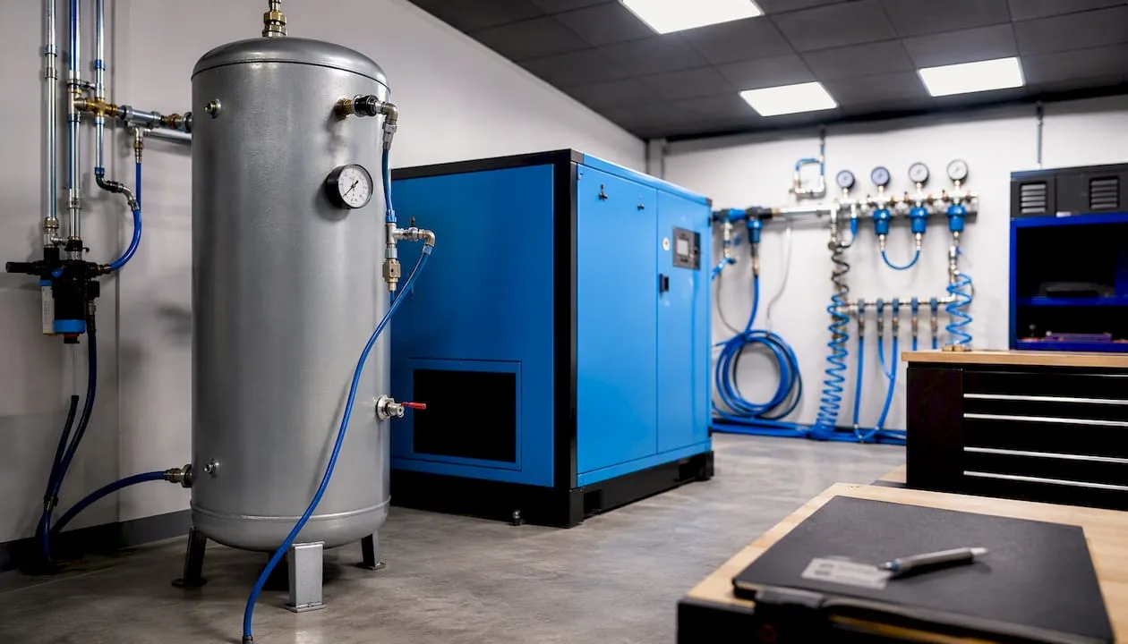
Pressure equalisation and peak coverage. During a short-term increase in demand, the air tank supplies air from its own reserve without the compressor having to start immediately. The pressure in the distribution system remains stable, which is critical for pneumatic tools, spray guns and automated lines, where pressure fluctuations cause defective products or malfunctions.
Reducing the number of compressor starts. Each compressor start puts a load on the motor, starter and valves. The air tank extends the intervals between starts by covering demand from the accumulated reserve. The result is lower wear and a longer service life of the machine. Properly sizing the air tank together with eliminating air leaks can bring significant energy savings, as shown by the energy savings guide on the Kompresory-vzduchotechnika blog.
Cooling and moisture condensation. Air cools down in the air tank and moisture condenses before entering the dryer. The dryer thus processes air with a lower water content, works more efficiently, and its sorption or cooling capacity is less burdened.
Safety reserve. In the event of a compressor failure, the air tank provides a reserve of air for the controlled shutdown of machines or completion of a safety sequence.
The air tank is not a passive vessel. A properly sized air tank reduces compressor starts and operating costs, while also relieving the dryer and stabilising air quality throughout the distribution system.
How to size an air tank?
Sizing an air tank is based on four input parameters: required flow rate, operating pressure, permissible pressure drop and supply time.
Input parameters:
- Compressor flow rate: Q (l/s or m³/min)
- Maximum operating pressure: P₁ (bar absolute)
- Minimum permissible pressure in the distribution system: P₂ (bar absolute)
- Required supply time without a compressor: t (min)
Basic formula for air receiver volume:
V = (Q × t × P₀) / (P₁ P₂)
where P₀ = 1 bar (atmospheric pressure as the reference value), Q is the flow rate in l/min, t is the time in minutes, P₁ and P₂ are absolute pressures in bar. The formula is based on an isothermal simplification; in practice, add a 10–20% margin for temperature deviations and leaks.
Example calculation for typical operation:
The compressor delivers Q = 300 l/min. Operating pressure P₁ = 8 bar abs., minimum permissible pressure P₂ = 6 bar abs. The air receiver must cover the peak for a period of t = 1 min.
V = (300 × 1 × 1) / (8 6) = 300 / 2 = 150 litres
With a 15% margin, the recommended volume comes out to approximately 170 litres. For more detailed setting of switching cycles, we also recommend the guide to the compressor duty cycle.
Reference table: compressor flow rate vs. recommended tank volume
| Compressor flow rate (l/min) | Recommended tank volume (l) |
|---|---|
| up to 100 | 24 |
| 100–300 | 150–170 |
| 300 | 150–170 |
| over 1000 | 1,000 and more |
The values are indicative for an operating pressure of 7–10 bar and a supply time of 1 min. Specific applications may require different sizing.
What types of air tanks are available?
Tanks differ in orientation, function within the piping system, pressure classes, and material.
Vertical vs. horizontal design. Vertical air receivers take up less floor space and condensate naturally flows to the bottom toward the drain valve. Horizontal air receivers are suitable for spaces with low ceilings or for mobile applications, but require careful placement of the drain valve at the lowest point.
Wet and dry tanks. A wet tank is installed directly after the compressor, before the dryer. It captures condensate and heat from the compressor and reduces the moisture load on the dryer. A dry tank is located after the dryer and stores already treated air without the risk of recondensation.
Pressure classes and material:
- Standard air tanks: up to 11 bar, suitable for most workshop and industrial applications
- High-pressure air tanks: 15–40 bar, for special industrial or filling applications
- Material: structural steel with epoxy or zinc coating (standard), stainless steel for food, pharmaceutical, or environments with aggressive media
- Connections: standard threaded (BSP or NPT), flanged for larger tanks
When selecting an air tank for connection to a dryer, verify the compatibility of connection diameters and the location of the inlet and outlet ports.
How to correctly install and position the air tank?
The installation of the air tank directly affects its reliability and accessibility for servicing.
Installation checklist:
- Solid concrete or steel foundation with sufficient load-bearing capacity
- Anchoring of the air tank according to the manufacturer's instructions (vertical air tanks especially when over 1 m in height)
- Minimum distance of 0.5 m from walls and machines for access to fittings
- Drain valve at the lowest point of the tank, accessible without dismantling the piping
- Pressure gauge positioned at a height readable by the operator
- Safety valve on the discharge port, uncovered and unblocked
Connection to the distribution system and dryer. The piping between the compressor and the air tank should be as short as possible to minimize pressure losses. After the air tank (or after the dryer in the case of a dry air tank), install a filter to capture remaining impurities. Automatic timer-controlled drain valves or float drains ensure regular condensate drainage without the need for manual intervention.
Professional tip: In environments with high air humidity (paint shop, food processing facility), install flexible compensators on the air tank's inlet piping. This will reduce the transmission of vibrations from the compressor and also reduce the risk of corrosion damage to flanges caused by mechanical stress.
Requirements for the compressor room, ventilation, and safety distances are summarized in the compressor room guide on the Kompresory-vzduchotechnika website.
How to maintain the air tank and ensure its safe operation?
Regular maintenance extends the air tank's service life and is a condition for the validity of inspections according to Czech regulations.
Recommended inspection intervals:
- Daily or before each shift: visual inspection of the pressure gauge, condition of the safety valve, and tightness of connections
- Monthly: visual inspection of the tank's external surface (corrosion, mechanical damage, coating), function of the drain valve
- Annually: internal inspection of the tank (corrosion, deposits, condition of welds), safety valve test, pressure gauge inspection, entry in the operating log
- According to Czech regulations: pressure vessels are subject to inspections according to applicable technical standards and government regulations; the interval and scope of the inspection are determined by the inspection technician based on the vessel category
Safety notice: If you suspect corrosion of the tank walls, deformation, or air leakage from the receiver body, immediately take the receiver out of operation, reduce the pressure to zero, and call a inspection technician. Never weld or drill into the air receiver without expert assessment.
Draining condensate is the most commonly neglected part of maintenance. Condensate contains oil, rust and microorganisms; its accumulation accelerates corrosion of the tank bottom and degrades air quality. An automatic float-type or electronic condensate drain eliminates the need for manual draining and ensures regular removal even during continuous operation.
How does the air receiver affect operating costs?
The air receiver reduces costs through three mechanisms: fewer compressor switching cycles, longer running under load, and lower component wear.
Savings mechanisms:
- Every unnecessary compressor start consumes several times more energy than operation in steady state; the air receiver eliminates these starts
- Stable pressure in the distribution system reduces air consumption of pneumatic tools and prevents overpressurization
- Fewer switching cycles mean less wear on valves, bearings and the starter, resulting in lower spare parts costs
Simple ROI example. A compressor with a power input of 7.5 kW starts on average 20 times per hour without an air receiver. After installing a properly sized air receiver, the number of starts drops to 4–6 per hour. At an electricity price of CZK 5/kWh and 2,000 operating hours per year, the savings from optimized switching and reduced losses show up both in the electricity bill and in service costs. Eliminating air leaks combined with correctly sizing the air receiver can bring energy savings in the order of tens of percent, as documented by an internal analysis by Kompresory-vzduchotechnika.
When deciding between a larger air receiver and an additional compressor or controlled switching, the overview of compressed air automation and consumption optimization can help.
Kompresory-vzduchotechnika will help you choose and service your air receiver
Kompresory-vzduchotechnika offers air receivers ranging from small service tanks (24–100 l) up to stationary industrial air receivers over 1,000 l, including stainless steel versions for demanding environments. Every delivery includes technical consultation: we help with volume calculation, pressure class selection, and designing the sequence of equipment in the piping.
Services include turnkey system design, installation, pressure vessel inspections, and energy audits of compressor rooms. The entire range of pneumatics and air technology is available in the e-shop. For a free sizing consultation, contact the technical department of Kompresory-vzduchotechnika directly via the website.
Key findings
An air tank is an active element of the compressed air system, whose correct sizing and maintenance directly affect energy consumption, compressor service life, and the quality of the supplied air.
| Point | Details |
|---|---|
| Role of the air tank | Equalizes pressure, covers demand peaks, and reduces the number of compressor cycles. |
| Sizing | The air tank volume is calculated from the flow rate, pressure band, and required supply time; add a reserve of 10–20%. |
| Types of air tanks | A wet air tank is placed before the dryer, a dry air tank after the dryer; choose a vertical or horizontal design depending on the available space. |
| Maintenance | Visual inspection monthly, internal inspection annually, revision according to Czech regulations depending on the vessel category. |
| Kompresory-vzduchotechnika | Offers air receivers, sizing design, installation and revisions; consultation available via the e-shop. |
The air receiver that technicians underestimate
The air receiver tends to be an overlooked item in compressed air projects. Technicians focus on compressor output, the type of dryer and filtration, but treat the air receiver as an "extra tank." Yet it is precisely the air receiver that determines how many times per hour the compressor starts, and thus directly determines how quickly the motor and valves wear out.
The most common mistake I see in operations is an undersized air receiver on compressors with a frequency inverter. Technicians assume that the inverter will handle switching on its own. However, without a sufficiently sized air receiver, the inverter oscillates within a narrow pressure band and the compressor never reaches its optimal operating point. The result is higher consumption than would occur with a correctly sized air receiver combined with a fixed-speed unit.
Before making any decision about the air receiver size, measure the actual flow and pressure band in operation. Compressor catalogue values and the actual consumption of the application differ, sometimes significantly. A compressed air consumption audit is the fastest way to obtain a figure that makes the calculation meaningful.
Useful resources and further reading
For further study of this topic, we recommend the following Kompresory-vzduchotechnika pages:
- Optimizing compressed air consumption — practical procedures for reducing the energy demands of operation
- Compressor duty cycle — a technical guide for setting switching strategies
- Basic requirements for a compressor room — installation and safety requirements including ventilation
- Selecting an industrial compressor — criteria for comparing output and capacity
Note on inspections and legislation: Pressure vessels (including air tanks) are subject to technical standards and relevant government regulations in the Czech Republic. Verify specific requirements for inspections, categorization, and documentation with a certified inspection technician or the relevant inspection authority. Regularly update equipment technical sheets and keep records of all service interventions.
Frequently Asked Questions
What is the main role of an air tank in the system?
The air tank balances pressure in the distribution system, covers short-term consumption peaks, and reduces the number of compressor cycles, thereby extending its service life.
What size air tank do I need for a 300 l/min compressor?
A typical application requires an air tank with a volume of 150–170 litres for a compressor with a flow rate of 300 l/min, a pressure range of 6–8 bar, and a supply time of 1 min, including a reserve for temperature variations and leaks.
Where in the piping should the air tank be installed, before or after the dryer?
A wet air tank belongs before the dryer (it collects condensate from the compressor), a dry air tank belongs after the dryer (it stores treated air).
How often should an air tank be inspected?
A visual inspection of the exterior is performed monthly, an internal inspection annually. Inspections according to Czech regulations depend on the pressure vessel category and are determined by an inspection technician.
Will Kompresory-vzduchotechnika help with selecting an air tank?
Yes. Kompresory-vzduchotechnika offers technical consultation, sizing calculations, supply of air tanks, and service support; a consultation can be arranged directly through the e-shop.
Recommended
- List of tasks for compressed air: a guide for technicians - Kompresory-Vzduchotechnika.cz
- Compressed air storage options: a guide for technicians - Kompresory-Vzduchotechnika.cz
- A guide to industrial air distribution: operating efficiency - Kompresory-Vzduchotechnika.cz
- How to store air hoses correctly: a guide for tradespeople - Kompresory-Vzduchotechnika.cz

The role of a flow meter in pneumatics: a technical guide
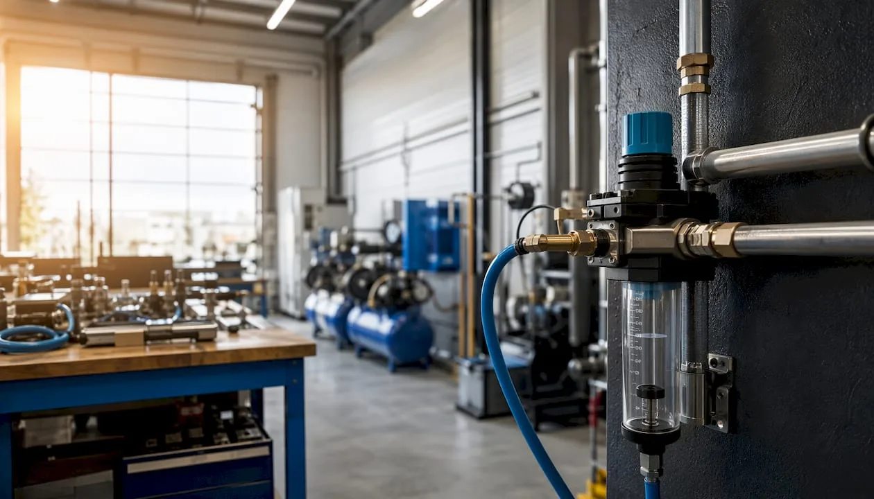
A flow meter in a pneumatic system performs one essential function: it verifies that the system is actually delivering the volume of compressed air that actuators and processes require. Without this measurement, you are operating the system blindly. Insufficient flow reduces pressure directly at the point of use, slows cylinder movement, and reduces their force. Conversely, excess flow without measurement means unnecessary energy costs. Install the flow meter first on the main supply line and on branches to production machines, where you will identify the largest losses.
- Consumption diagnostics: monitoring actual consumption per machine or line
- Leak detection: comparing flow in idle and operating modes reveals air leaks
- Verification of actuator performance: checking whether cylinders receive the required flow for correct speed and force
A flow meter is not just a measuring instrument. It is a diagnostic tool that determines whether your pneumatic system is operating as designed, or only approximately.
Professional tip: When first deploying a flow meter, measure consumption in idle state (without production). Any non-zero flow indicates leaks, which directly increase compressor costs.
Contents
- Why measure compressed air flow?
- What principles and types of flow meters are suitable for pneumatics?
- How to choose a flow meter for compressed air?
- How to correctly install a flow meter in a pneumatic distribution system?
- How to calibrate and maintain a flow meter?
- Practical applications and calculation examples
- Available technologies and support for the Czech market
- Key Takeaways
- Flow meter as the first step of an energy audit
- Kompresory-vzduchotechnika: measurement, design and service in one place
- Selected sources and further reading
- FAQ
Why measure compressed air flow?
Flow measurement delivers concrete operational and economic results. Without data on actual consumption, it is not possible to effectively manage compressed air energy use or plan compressor capacity.
- Energy savings: identifying losses and optimizing operating cycles reduces compressor power input; compressed air consumption optimization starts precisely with measurement
- Leak quantification: continuous measurement on main branches with comparative analysis of idle and operating flow reliably detects and quantifies leaks
- Verification of actuator performance: the correct speed and force of cylinders depends on the delivered flow, not just the set pressure
- Energy audits and reporting: the flow meter provides data for monitoring consumption by department, machine, or product, which is essential for both internal and external audits
- Return on investment calculation: measuring consumption before and after optimization gives an accurate figure for savings; a typical example is packaging lines, where isolated measurement of each station reveals which one consumes disproportionately
The relationship between flow and actuator performance is direct. If a cylinder does not receive sufficient flow, movement slows down or force drops below the required value. A pressure gauge will not detect this situation, because the pressure at the supply may be fine while the flow is restricted by a bottleneck in the piping.
What principles and types of flow meters are suitable for pneumatics?
Several measurement principles are applicable to compressed air. Each has different strengths and different limitations.
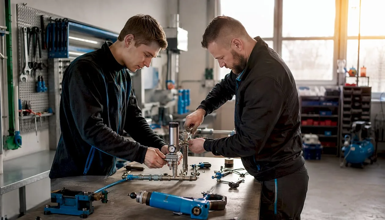
Thermal (calorimetric) mass flow meters operate on the principle of a heated sensor: the probe measures the heat loss from the heated element caused by the flowing gas. The result is directly in mass or normalized units (Nm³/h) without the need to convert to current pressure and temperature. For this reason, they are the most commonly preferred choice for compressed air, especially for low flows and applications with variable pressure.
Differential pressure flow meters (orifice plates, nozzles, Venturi tubes) are among the most widespread in industry. They are robust and proven, but require precise installation, since turbulence significantly affects accuracy. The result depends on pressure and temperature, so conversion to normalized conditions is necessary.
Turbine and vane flow meters are sensitive to the cleanliness of the medium. Condensate or oil in the piping quickly damages the rotating parts. They require straight sections of piping before and after the meter.
Ultrasonic flow meters enable non-invasive measurement from outside the pipe without interrupting operation. They minimize pressure losses and are suitable where intervention in the piping is not possible.
Coriolis flow meters measure mass flow and density with high accuracy, independent of pressure, temperature, and viscosity. However, they are more expensive and are used where accuracy directly affects the process or billing.
Electromagnetic (inductive) flow meters are intended exclusively for electrically conductive liquids, and are therefore not suitable for compressed air.
| Principle | Advantages | Disadvantages | Typical Application |
|---|---|---|---|
| Thermal Mass | Independence from PT, direct Nm³/h, low flow rates | Sensitivity to oil and condensate | Main distribution lines, leak detection |
| Differential Pressure | Robust, proven, low cost | Dependence on PT, need for recalculations | Industrial distribution lines, high flow rates |
| Turbine | Good accuracy, fast response | Sensitive to contaminants, straight pipe sections required | Clean air, medium flow rates |
| Ultrasonic | Non-invasive, no pressure loss | Higher cost, affected by flow profile | Retrofit, no need to cut into the piping |
| Coriolis | Highest accuracy, mass measurement | High cost, larger dimensions | Critical processes, billing |

Professional tip: If the distribution system contains condensate or traces of oil, prefer a thermal mass flow meter with an upstream oil and condensate separator. Turbine and vane types deteriorate quickly in such an environment.
How to choose a flow meter for compressed air?
Selecting a flow meter depends on a combination of operating parameters. No single criterion is sufficient.
Key selection criteria:
- Measurement range (rangeability): the ratio of maximum to minimum measurable flow; for systems with variable consumption, choose a flow meter with a rangeability of at least 10:1
- Accuracy and repeatability: ±2–3% is sufficient for energy audits, while ±0.5–1% is required for billing or critical processes
- Pressure drop: differential pressure types cause a higher pressure drop than ultrasonic or thermal types
- Resistance to contaminants: oil and condensate will damage turbine types; thermal sensors require clean air or upstream filtration
- Operating pressure and temperature: verify that the device covers the entire range of operating conditions
- Materials and connections: threaded or flanged connection, body and seal materials must match the operating medium
- Certification and calibration traceability: for audits and metrology requirements, require a calibration certificate traceable to a national standard
The effect of pressure and temperature on measurement is critical for volumetric flow meters. The flow measured at an operating pressure of 7 bar differs significantly from the value at atmospheric pressure. Thermal mass flow meters perform this conversion automatically. For other types, the measured value must be converted to normal conditions (Nm³/h at 0 °C and 101.325 kPa) or temperature and pressure compensation must be used.
Example flow calculation for a cylinder:
- Failure to observe these sections causes turbulence, which leads to non-linear measurement and percent-level errors.
- Add the volume for the return stroke (smaller piston area due to the rod)
- Multiply by the cycle frequency: 20 cycles/min × 0.624 l = 12.5 l/min at operating pressure
- Convert to normalized conditions: at 7 bar (abs) ≈ 87.5 Nl/min = 5.25 Nm³/h
This calculation determines the minimum flow rate that the flow meter must reliably measure. Add a reserve for other consumers on the branch.
The flow coefficient Cv of valves directly affects how much air can pass through the control valve. An undersized valve creates a bottleneck that cannot be compensated for by higher compressor pressure. Cv must be recalculated for compressible gas, not just for liquids. A flow meter placed downstream of the valve reveals whether the valve actually allows the required flow rate to pass. More about the relationship between valves and flow can be found in a separate article.
How to properly install a flow meter in a pneumatic distribution system?
Installation determines the accuracy of measurement just as much as the quality of the device itself. In practice, installation errors are a more common cause of deviations than sensor errors.
Requirements for straight sections:
- Turbine and vane flow meters: at least 10× the pipe diameter upstream of the meter and 5× downstream
- Thermal mass flow meters: typically 5–10× the diameter upstream, 3–5× downstream (depending on manufacturer)
- Differential pressure types: 20× the diameter upstream and 5× downstream for orifice plates; less for Venturi tubes
Failure to observe these sections causes turbulence, which leads to non-linear measurement and errors of a percentage order.
Installation procedure:
- Plan the piping route and verify the availability of the required straight sections
- Install a filter upstream, a condensate separator and an oil separator immediately before the meter
- Install the flow meter in the correct orientation (horizontally or vertically according to the manufacturer's specification)
- Check the seals and tightness of connections; use seals compatible with the pressure medium
- Install simultaneous pressure and temperature measurement if the flow meter does not perform compensation automatically
- Set up a bypass or shut-off valves to allow replacement without shutting down the line
- Verify zero flow with the system closed (zero point check)
Placement recommendations: the main supply line will capture total consumption, branching to individual machines will allow leak localization, measurement close to the consumer will verify the performance of a specific drive.
Professional tip: Design a bypass with shut-off valves on both sides of the flow meter. This way, you won't need to shut down the entire line during calibration or sensor replacement. This small investment in installation will save hours of downtime at every maintenance.
How to calibrate and maintain a flow meter?
Flow meter accuracy changes over time. Regular calibration and maintenance are a prerequisite for data usable in energy audits.
Recommended intervals and procedures:
- Initial check after installation: verify the zero point and compare with a reference meter or a known volume
- Annual calibration for critical applications: for flow meters used in energy reporting or billing; for less critical applications, calibration every two years is sufficient
- Drift monitoring: regular comparison with a portable reference meter or with pressure test results will reveal drift before it causes data errors
- Sensor cleaning: thermal sensors are sensitive to oil deposits; clean according to the manufacturer's recommendations, usually at each annual inspection
- Seal inspection: at each inspection, check the tightness of joints and the condition of seals
Flow meters in industrial facilities fulfil three main roles: consumption measurement, leak detection, and verification of actuator performance.
- OK Zbytek:
- Open to a control flow rate and compare with a reference instrument or a calculated value
- Record the result in the instrument's log card
A calibration audit trail is a mandatory document for energy audits under ČSN EN ISO 50001. Without it, the credibility of the measured data cannot be demonstrated.
Practical applications and calculation examples
Flow meters in industrial facilities fulfil three main roles: consumption measurement, leak detection, and verification of drive performance.
Measuring consumption of a machine line: a flow meter on the line's supply records total consumption in Nm³/cycle or Nm³/h. Comparison with the projected value reveals whether the line is operating efficiently or whether consumption has changed (seal wear, process change).
Leak detection on a branched distribution system: flow meters on the main branch and on the outputs to individual sections enable balance measurement. The difference between inflow and the sum of outflows corresponds to the leak. Measurement in idle state (without production) then directly quantifies leaks.
Sample calculation of savings from eliminating a leak:
- Measured flow in idle state: 15 Nm³/h
- Operating pressure: 7 bar, compressor power input: approximately 0.1 kWh/Nm³
- Annual loss: 15 Nm³/h × 8,000 h × 0.1 kWh/Nm³ = 12,000 kWh/year
- At an electricity price of CZK 4/kWh: CZK 48,000/year on leaks alone
Data interpretation: flow peaks during machine start-up are normal. An anomaly occurs if the idle-state flow does not drop to zero, or if the peaks exceed the projected value. Both indicate either leaks or an undersized distribution system.
Recommended reporting metrics: Nm³/h (instantaneous flow), Nm³/cycle (consumption per production cycle), specific consumption per product (Nm³/pc).
Warning: condensate or oil in the piping will cause incorrect results with both thermal sensors (deposits on the probe) and turbine types (mechanical damage). Diagnostics: if the flow meter shows nonzero flow with the system closed, or significantly fluctuating values with no apparent cause, check the upstream filtration and the sensor's condition.
Available technologies and support for the Czech market
All major flow meter technologies for compressed air are available on the Czech market: thermal mass, differential pressure, turbine, and ultrasonic. For industrial applications in the Czech Republic, thermal mass flow meters are most commonly deployed for distribution lines, and differential pressure types for larger pipe diameters.
- Thermal mass flow meters: available from a range of suppliers, suitable for the DN15–DN100 range, typical operating pressures up to 16 bar
- Ultrasonic types: suitable for retrofitting existing distribution systems without the need to intervene in the piping
- Differential pressure types: standard solution for larger diameters and high flow rates
Kompresory-vzduchotechnika offers complete support from flow meter selection through installation design to calibration and service. Services include consumption measurement and reporting, turnkey solution design, equipment supply, installation, calibration, and 24/7 service. For a pilot measurement, we recommend starting with a single flow meter on the main supply line or on the most problematic branch.
Professional tip: Before requesting a quote, prepare a distribution diagram with marked pipe diameters, operating pressures, and required measurement points. Add the required accuracy and goals (leak detection, energy audit, performance verification). With this documentation, you will receive a specific offer instead of a general catalog.
Key findings
A flow meter in a pneumatic system is an essential tool for diagnosing consumption, detecting leaks, and verifying actuator performance, with the correct choice of technology and installation directly determining the reliability of the measured data.
| Point | Details |
|---|---|
| Main role of the flow meter | Consumption diagnostics, leak detection, and flow verification for actuators are three key functions. |
| Technology selection | For compressed air, thermal mass flow meters are the most commonly preferred choice due to their independence from pressure and temperature. |
| Installation and straight sections | Turbine types require 10× diameter upstream and 5× downstream of the meter; failure to comply causes errors on the order of a few percent. |
| Calibration and audit | Annual calibration with an audit trail is a prerequisite for data usable in energy audits according to ČSN EN ISO 50001. |
| Compressors-air technology | It offers selection, supply, installation and calibration of flow meters, including energy audits and non-stop service. |
Flow meter as the first step of an energy audit
Flow meters tend to be underestimated in practice. Technicians address pressure, compressor output, and filter condition, but they only measure flow once the problem has fully manifested. This is a mistake that makes operation more expensive.
The most common mistake that recurs in operation: installing the flow meter in the wrong location without upstream filtration. The sensor becomes clogged with oil or condensate, the data becomes unreliable, and the technician concludes that the flow meter "doesn't work." However, the problem is not with the device, but with the installation. The correct order is always: filtration, condensate separator, oil separator, and only then the flow meter.
A second recurring problem is the failure to maintain straight pipe runs. Piping in industrial facilities is often routed with regard to available space, not metrology. An elbow positioned just before the meter causes turbulence that distorts the reading. Planning the pipe route with regard to the flow meter's installation requirements must take place at the design stage, not during installation.
Recommendation for technicians: start with a single flow meter on the main supply line, measure the baseline flow, and compare it to the designed value. The result of the first measurement will almost always reveal either leaks or an undersized distribution system. Only based on this data should you decide on further expansion of the measurement infrastructure.
Kompresory-vzduchotechnika: measurement, design, and service in one place
If you want to actually measure the flow of compressed air rather than just estimate it, Kompresory-vzduchotechnika offers a direct path from device selection to commissioning and calibration.
Services include consumption measurement and report processing, design of measurement points according to the distribution scheme, supply of flow meters for all common diameters and pressures, installation in compliance with installation requirements, calibration with certificate issuance, and 24/7 service. For energy audits, we provide a complete measurement campaign including documentation.
A pilot measurement can be ordered as a standalone service: we bring a portable flow meter, measure consumption at selected points, and provide a report with recommendations. The complete range of flow meters and accessories for pneumatic systems is available online. For consultation on selection or to order a pilot measurement, contact the technical department of Kompresory-vzduchotechnika directly via the website.
Selected sources and further reading
For deeper study and verification of technical parameters, we recommend the following sources:
- ČSN EN ISO 5167 (measurement of fluid flow by differential pressure devices): normative basis for orifice plates, nozzles, and Venturi tubes
- ČSN EN ISO 50001 (energy management systems): requirements for measuring and recording energy consumption, including compressed air
- TZB-info, Industrial Technology section: overview articles on flow meter principles and installation requirements
- How to choose an air flow meter on Kompresory-vzduchotechnika.cz: a technical comparison of technologies with practical recommendations
- Methods for Testing Air Flow: a guide to measurement techniques for technicians
- Procedure for Solving Air Leaks: step by step from detection to correction
When preparing an inquiry or a pilot measurement, we recommend first studying the normative requirements of ČSN EN ISO 50001 for measuring points and accuracy, and then consulting the choice of technology with the supplier based on the specific distribution scheme.
Frequently asked questions
How does a flow meter work in compressed air?
A flow meter measures the volume or mass of air passing through a pipe per unit of time. The principle depends on the technology: a thermal sensor measures the cooling of a heated element, a differential pressure type measures the pressure drop across a primary element, and a turbine type counts the rotor revolutions.
How does a mass flow meter work?
A thermal mass flow meter heats a sensor element and measures how much heat the flowing gas removes. A higher flow rate causes greater cooling. The result is given directly in mass or normalized units (Nm³/h) without dependence on the current pressure and temperature.
How does an inductive (electromagnetic) flow meter work?
An electromagnetic flow meter measures the flow of electrically conductive liquids based on Faraday's law of electromagnetic induction. It is not suitable for compressed air, because air is not electrically conductive.
Which type of flow meter is best for leak detection?
Thermal mass flow meters are the most suitable for leak detection: they measure directly in Nm³/h without conversions, have good sensitivity at low flow rates, and allow continuous monitoring with comparative analysis of idle and operating states.
How often does a flow meter need to be calibrated?
For flow meters used in energy reporting or audits, annual calibration with issuance of a certificate traceable to a national standard is recommended. For less critical applications, calibration every two years is sufficient, supplemented by ongoing drift monitoring using a portable reference meter.
Recommended
- Pneumatic systems explained: a guide for technicians - Kompresory-Vzduchotechnika.cz
- What is pneumatic lubrication: a guide for technicians - Kompresory-Vzduchotechnika.cz
- Why use pneumatics: efficiency, speed and safety - Kompresory-Vzduchotechnika.cz
- How pneumatics works: a complete guide for industry 2026


Spray gun maintenance guide: for professionals and DIY users
In brief:
- Regular maintenance and immediate cleaning after use extend the service life of the spray gun. Before disassembly, the gun must be disconnected from the air supply, the pressure released, and protective equipment used.
The best way to keep a spray gun functional and safe is to clean it immediately after each use, regularly check the seals, and ensure clean compressed air with 3-stage filtration. Proper maintenance can significantly extend the gun's service life and permanently ensure even spray patterns.
Three steps that must not be skipped after each job:
- Immediately empty the bowl and flush the system with water (water-based paints) or the appropriate thinner (synthetic and solvent-based paints).
- Disconnect the gun from the compressed air source and release the residual pressure before any disassembly.
- Ensure clean compressed air: a 3-stage filter with pressure regulator and a hose with an inner diameter of at least 9 mm.
Contents
- Safety first: what to do before disassembly
- What tools and cleaning agents will you need?
- Detailed guide to cleaning and maintaining the spray gun
- How often should you inspect the gun and what to look for?
- How to remove clogging and other common faults of a spray gun?
- Why does clean compressed air determine the quality of the spray finish?
- How to properly store the gun after maintenance?
- Which spare parts should you always have on hand?
- Key takeaways
- Gun maintenance: what really determines the result
- Where to get parts and accessories for a spray gun?
- Useful resources and manuals
- Frequently asked questions
Safety first: what to do before disassembly
Neglecting safety steps before cleaning is the most common cause of injuries when working with pneumatic tools. Pressure in the system can cause serious injury, so the order of the steps is mandatory, not just recommended.
Protective equipment for cleaning and maintenance:
- Respirator suitable for the solvent or paint used (minimum FFP2 for organic vapours).
- Safety glasses with side shields, not just regular work glasses.
- Nitrile gloves resistant to solvents; latex is not sufficient.
- Long sleeves or a work coverall to protect the skin from overspray.
Never immerse the entire gun in aggressive solvent. Prolonged immersion will permanently damage the internal seals and the surface finish of the gun body. Clean only the parts that come into direct contact with paint.
What tools and cleaning agents will you need?
Preparing everything in advance saves time and prevents improvisation, which leads to damage to parts.
Basic tools:
- Flathead and Phillips screwdriver (size depends on the gun model).
- Box wrenches or open-end wrenches for the nozzle and air cap nuts.
- A set of fine brushes for nozzles and channels (diameters 1–4 mm).
- Bristles or thin wires for checking the patency of nozzle openings.
- Clean rags or lint-free paper towels.
Cleaning agents by paint type:
- Water-based paints (acrylic, latex): clean water, possibly a mild washing agent.
- Synthetic and alkyd paints: thinner specified in the paint manufacturer's technical data sheet (most often white spirit or mineral spirit).
- Two-component and epoxy paints: special cleaner recommended by the manufacturer, work within the time limit before gelation.
Spare parts to keep in stock:
- Set of O-rings and gaskets for the given spray gun model.
- Spare needle and nozzle (at least one complete set).
- Filters for the bowl or the spray gun's inlet filter.
- Silicone grease or lubricant recommended by the manufacturer for lubricating the needle and moving parts.
Detailed instructions for cleaning and maintaining a spray gun
The entire procedure takes 15–25 minutes with routine practice. For the first cleaning, allow more time and have the manual for your model on hand.
1. Safety preparation Disconnect the hose from the gun. Pull the trigger aimed into a waste container until all air and pressure has escaped. Put on protective equipment.
2. Emptying the bowl and flushing the system Unscrew the bowl and pour the remaining paint back into the original container. Pour cleaning agent (water or thinner) into the bowl, screw it back on, and spray into a waste container until clear liquid comes out. Repeat once or twice depending on the level of contamination.
3. Disassembly and cleaning of the nozzle, needle, and air cap Unscrew the air cap and nozzle. Remove the needle after loosening the locking nut. Immerse all parts in cleaning agent in a small container (not the entire gun). Clean the nozzle channels with a brush and a thread; never use a metal wire, as it would widen the hole and permanently damage the nozzle geometry.
4. Checking O-rings, seals, and lubrication Inspect each O-ring and seal under good lighting. Cracks, flattening, or hardness indicate the need for replacement. Lightly coat the needle and moving parts with silicone grease. Wipe off excess grease to prevent it from getting into the paint.
5. Blowing out, checking, and assembling Briefly blow out the gun channels with compressed air (without paint). Assemble the gun in the reverse order of disassembly: needle, nozzle, air cap. Tighten the nuts firmly, but without excessive force that could damage the threads.
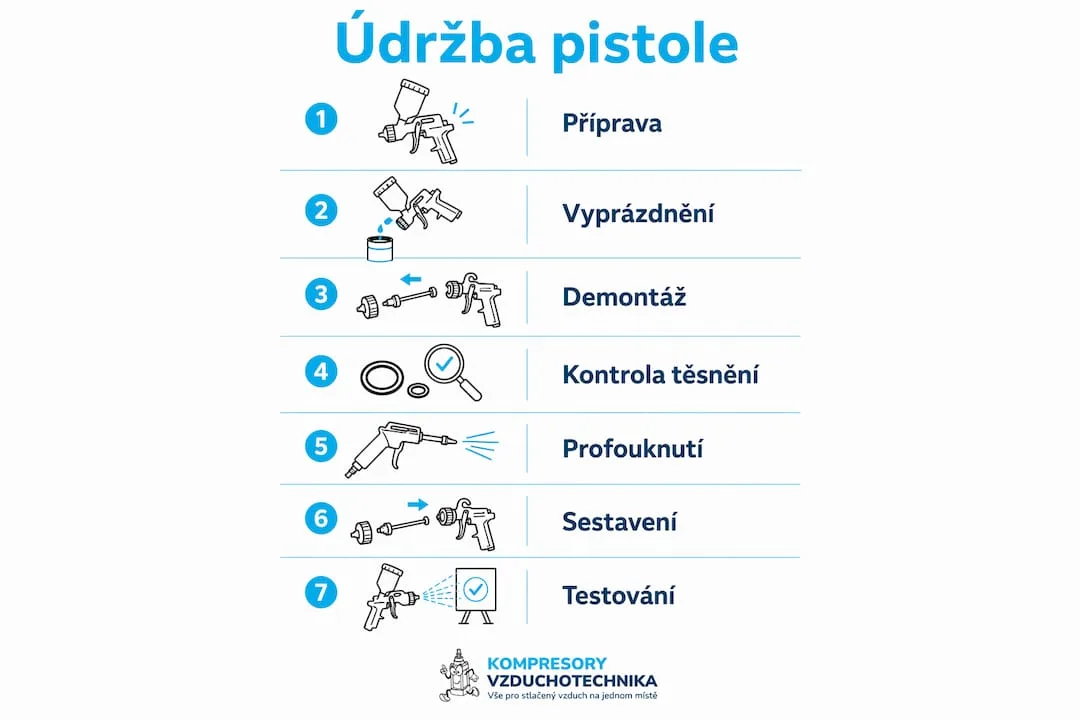
6. Checking the spray pattern Connect the hose, set the pressure, and spray a test sample onto a piece of cardboard. A correct pattern is a symmetrical ellipse without streaks, drips, or dry edges.
| Spray pattern | Probable cause | Solution |
|---|---|---|
| Symmetrical ellipse | Everything is fine | Continue working |
| Heavier on one side | Clogged air cap hole | Clean with a brush |
| Drops in the middle | Worn needle or nozzle | Replace the part |
| Dry, frayed edge | Low pressure or clogged filter | Increase pressure, check filter |
| Spray pattern too wide | Pressure too high | Reduce pressure in steps |
Professional tip: Always start with a lower pressure and increase it gradually in small increments until you achieve the correct pattern. Testing on cardboard before each job reveals nozzle wear before it shows up on the painted surface.
How often should the gun be inspected and what to check?
Regular preventive inspection is cheaper than repairs caused by neglected maintenance. The frequency depends on the intensity of use.
| Interval | What to check |
|---|---|
| After each use | Cleanliness of the nozzle, needle and bowl; system flushing |
| Daily / after each shift | Condition of seals, filter flow, joint tightness |
| Monthly | Complete disassembly, inspection of O-rings, lubrication, hose condition |
| Annually | Service inspection, pressure regulator calibration, replacement of preventive parts |
Specific inspection points for the monthly check:
- Nozzle: visual inspection of orifice edge wear; a change in the spray pattern is the first sign.
- Needle: straightness, surface free of scratches or corrosion.
- Seals and O-rings: elasticity, integrity, absence of cracks.
- Gun air filter: cleanliness of the element, absence of condensate.
- Pressure regulator: stability of the set value under flow.
- Hoses and fittings: no cracks, properly tightened, leak-free.
Keeping a simple maintenance log (date, tasks performed, parts replaced) will significantly speed up fault diagnosis and make it easier to order the correct spare parts. A table on your phone or a paper form kept with the gun is enough.
How to clear clogging and other common spray gun faults?
Most problems can be solved directly in the workshop. The key is correct diagnosis before replacing parts.
| Fault | Cause | Quick fix |
|---|---|---|
| Clogged nozzle | Dried paint in the hole | Soak in cleaning agent, clean with a cleaning needle |
| Irregular or striped spray pattern | Worn needle/nozzle, incorrect pressure | Check the parts, adjust distance and overlap — |
| Dripping from the gun | Damaged seal or loose nut | Replace the seal, tighten the material flow nut |
| Impurities in the paint | Condensate or impurities in the air | Check and replace filters, check the dryer |
| Uneven coverage | Movement too fast or pressure too low | Slow down the movement (approx. 1 m per 3 s), increase the pressure |
Signs that professional service is required:
- Cracks or deformation of the gun body.
- Damaged nozzle or air cap threads.
- The pressure regulator does not hold the set value.
- Recurring fault after replacing the seal and nozzle.
Airless spray guns have different requirements for pressure and nozzle settings. When servicing them, always follow the manual for the specific model, as the operating pressures are significantly higher than those of conventional pneumatic guns.
Why does clean compressed air determine the quality of the spray finish?
Condensate, oil and solid contaminants in compressed air directly affect paint quality: they cause craters, impurities and uneven coverage. Air filtration is not an optional extra, but a condition for reliable operation.
Recommended air treatment setup:
- Stage 1: coarse filter to capture solid particles and water droplets.
- Stage 2: fine filter for oil aerosols and fine contaminants.
- Stage 3: pressure regulator with precise pressure gauge for stable working pressure.
For industrial operations, the relevant standard is ISO 8573, which defines compressed air purity classes and determines the choice of filters and dryers. An overview of compressor filters for industry will help you select the right combination for your specific operation.
| Parameter | Minimum requirement | Note |
|---|---|---|
| Hose inner diameter | ≥ 9 mm | A smaller diameter causes a pressure drop |
| Hose design | Antistatic | Prevention of electrostatic discharge during spraying |
| Filtration | 3-stage | Filter + pressure regulator |
| Condensate drainage | Automatic or manual | Drain regularly |
Do not use a hose with an internal diameter smaller than 9 mm, even for hobby applications. A pressure drop at the end of the hose leads to an unstable spray pattern and increased paint consumption. Choosing the right hose for air distribution is therefore just as important as setting the regulator.
How to properly store the gun after maintenance?
Proper storage extends the life of the seals and protects precision parts from deformation or corrosion.
Principles of short-term and long-term storage:
- Store the gun clean, dry and at a moderate temperature (5–40 °C), away from direct sunlight and heat sources.
- Before long-term storage (more than 2–3 weeks), lightly lubricate the needle and moving parts with silicone grease.
- Remove sensitive seals and store them separately in a dry, airtight container, if recommended by the manufacturer.
- Cover the nozzle and air cap with a protective cover or wrap them in a clean cloth.
- Never store the gun with paint in the bowl; dried paint will damage the seals and clog the system.
During transport:
- Protect the nozzle and needle from mechanical damage (a rigid case or protective packaging).
- Secure moving parts to prevent unintended movement.
- Do not transport the gun with a pressurized hose connected.
Professional tip: If you don't plan to use the gun for a longer period, put a few drops of silicone oil into the bowl, briefly cycle it through and let it drain out. The internal surfaces stay protected and the seals won't dry out.
Which spare parts should you always keep on hand?
Wear parts wear out predictably. Keeping them in stock means a fault won't stop work for hours or days while waiting for a delivery.
Most frequently worn parts:
- Nozzle: wear on the edge of the opening results in a change in the spray pattern; replace at the first signs.
- Needle: grooves or corrosion on the surface cause dripping and irregular material flow.
- O-rings and seals: cracks or loss of elasticity lead to leaks and dripping.
- Gun inlet filter: clogging causes a drop in flow and unstable pressure.
How to choose the right part:
- Find the part number in the manual or on the gun's rating plate.
- Compare it with the manufacturer's or supplier's catalog.
- Prefer original kits or quality replacement parts with technical specifications (seal material, nozzle diameter).
Kompresory-vzduchotechnika offers pneumatic spray guns and accessories including technical support for selecting the right part. Before ordering, have the gun model and part number from the manual ready.
Key takeaways
Regular spray gun maintenance, immediate cleaning after use, and clean compressed air with 3-stage filtration are the three conditions that determine the reliability and service life of the gun.
| Point | Details |
|---|---|
| Immediate cleaning | Flush the system immediately after use; dried paint clogs nozzles and damages seals. |
| Safety before disassembly | Always disconnect from the air supply and release the pressure as the first step, without exception. |
| Compressed air quality | A 3-stage filter with regulator and a hose with an internal diameter of ≥ 9 mm are a prerequisite for an even spray pattern. |
| Preventive parts replacement | Keep a set of seals, a needle, and a nozzle in stock; replace at the first signs of wear. |
| Kompresory-vzduchotechnika | Offers filters, hoses, spare parts kits, and technical consultation for selecting the right solution. |
Spray gun maintenance: what really determines the result
Most spray gun problems don't arise from wear, but from neglected cleaning. A gun that is left standing with paint in the system after work will clog before any mechanical wear becomes apparent. This applies equally to hobby users and professional paint shops.
The second thing that is often underestimated is air quality. Even the best-adjusted gun with clean nozzles won't give a good result if air with condensate or oil enters it. Investment in 3-stage filtration pays off on the very first job where no re-sanding or re-painting is needed.
For professional operations, I recommend keeping records of every service intervention. In the case of a recurring fault, the record is the fastest route to diagnosis and also serves as documentation for a warranty claim or spare parts order. For hobby users, a simple date and note of the replaced part is sufficient.
When to entrust the gun to a specialist: if the fault recurs after replacing the seal and nozzle, or if the pressure regulator doesn't hold the set value, it's time for a service inspection. Fixing it at an early stage is always cheaper than replacing the entire gun.
Where to get parts and accessories for a spray gun?
Kompresory-vzduchotechnika covers the entire chain from the air source to the gun. For spraying applications, this specifically means: air treatment units, filters, hoses, and spare parts for pneumatic guns.
For hobby workshops and light professional use, compact air treatment units up to 10 bar are suitable, combining filtration and pressure regulation in one compact unit. Industrial operations will appreciate SCR screw compressors with integrated air treatment for stable and clean air throughout the shift.
Before contacting technical support, please prepare: the gun model, the part number from the manual, and a brief description of the fault or request. This shortens the consultation time and increases the accuracy of the recommendation. Kompresory-vzduchotechnika technical support is available both online and by phone.
Useful resources and manuals
Manufacturer documentation is irreplaceable in service work. General manuals can serve as orientation, but specific torque values, nozzle diameters, and seal types are always specific to the given model.
Recommended resources:
- Spray gun manufacturer's manual: download from the manufacturer's website or request at purchase; store with the device or in a digital record.
- Technical data sheet for paint or varnish: determines the correct thinner and cleaning agent; change with every new batch.
- ISO 8573 standard: reference document for industrial facilities when designing air filtration.
- Internal guide Kompresory-vzduchotechnika: step-by-step spray gun maintenance with disassembly photographs and practical tips.
| Source | Type | Use |
|---|---|---|
| Spray gun manufacturer's manual | PDF / printed | Torque values, disassembly diagram, part numbers |
| Paint technical data sheet | PDF from paint manufacturer | Correct thinner, cleaning agent, working pressure |
| ISO 8573 | Standard | Air purity classes for industrial facilities |
| Kompresory-vzduchotechnika Blog | Internal article | Practical procedures, recommended accessories |
Keep the manual for each spray gun in operation accessible directly at the equipment or in a digital record. When ordering spare parts, the part number from the manual is the fastest way to find the correct component.
Frequently Asked Questions
How to correctly set up a spray gun before use?
Start with low pressure and increase it gradually in small increments. Verify the correct setting with a test spray on cardboard: the pattern should be a symmetrical ellipse without drips or dry edges.
What should be used to clean the spray gun after work?
Clean water-based paints with water, and synthetic and alkyd paints with the thinner specified in the paint manufacturer's technical data sheet. Never immerse the entire gun in solvent; clean only the parts in contact with paint.
What pressure should be set for a spray gun?
The working pressure depends on the gun model and the paint viscosity; always follow the recommendations of both the gun manufacturer and the paint manufacturer. As a general rule, start lower and increase in steps until the spray pattern is even.
How is paint thinned for a spray gun?
Thin the paint with the thinner recommended by the paint manufacturer to the viscosity specified in the technical data sheet. The correct viscosity can be verified with a flow cup (most commonly Ford Cup No. 4); paint that is too thick clogs the nozzles, while paint that is too thin causes runs.
How to remove a clogged spray gun nozzle?
Remove the nozzle, soak it in the appropriate cleaning agent, and clean the channels with a soft brush or cleaning wire. Never use a metal wire, as it would widen the nozzle opening and permanently alter the spray pattern.
Recommended

Why the pressure hose is important: a guide for technicians
The pressure hose determines the safety, reliability and efficiency of the entire pneumatic system. An unsuitable or damaged hose causes pressure losses, damages tools and, in extreme cases, leads to bursting with a risk of injury to the operator. Before each use, check the label with the working pressure and select the hose according to the STAMP methodology.
The main reasons why hose selection matters:
- Safety: bursting or leakage of medium under pressure endangers the operator and the surroundings
- Pressure losses: an unsuitable diameter or length reduces the available pressure at the tool; incorrect length and diameter can cause pressure losses in the range of 5 to 10%
- Tool protection: stable flow extends the service life of pneumatic tools
- Operational reliability: a quality hose reduces downtime and service costs
Contents
- What is a pressure hose and what are the basic types for workshop and construction use?
- How does a pressure hose affect operational safety?
- How does a pressure hose affect the efficiency and performance of the system?
- What technical parameters determine the correct choice of hose?
- How to choose the right pressure hose step by step (the STAMP methodology)
- How to correctly install, use and maintain a pressure hose?
- How to correctly store pressure hoses?
- What standards and certifications apply to pressure hoses in the Czech Republic and the EU?
- Practical recommendations for three typical operational scenarios
- Key takeaways
- Expert opinion on the selection and maintenance of pressure hoses
- Where can you find the right pressure hose and expert support?
- What documents and technical datasheets should you request from the supplier?
- Frequently asked questions
What is a pressure hose and what are the basic types for workshop and construction use?
A pressure hose is structurally designed to transfer media under pressure, i.e. compressed air, liquids or technical gases. It differs from a suction (extraction) hose in its reinforcement and wall thickness: a suction hose is dimensioned for negative pressure, while a pressure hose is dimensioned for positive pressure. Confusing these two types is one of the most common causes of accidents.
Main types by material and reinforcement:
- Rubber hoses with textile or steel braiding: high abrasion resistance, resistant to oils, solvents and extreme temperatures; suitable for construction and industry
- Polyurethane (PU) hoses: lightweight, flexible, resistant to oils and abrasion; maintain flexibility even at low temperatures (roughly down to around −40 °C), popular in workshop operations
- PTFE hoses: chemical resistance and temperature stability; suitable for aggressive media and high temperatures
- PVC hoses: most affordable, lightweight, but lower resistance and stiffen in cold conditions; only for occasional and less demanding use
- Steel-braided hoses (multi-layer): maximum pressure resistance, maintained flexibility; for high-pressure industrial applications
| Material | Main advantages | Disadvantages | Typical use |
|---|---|---|---|
| Braided rubber | Resistance to abrasion, oils and solvents, flexibility | Higher weight | Construction, industry |
| Polyurethane (PU) | Lightness, flexibility even in cold conditions, resistance to oils and abrasion | Higher price, sensitivity to some chemicals | Workshop, car service |
| PVC | Low price, lightness | Lower resistance, stiffens in cold | Occasional use, lighter tools |
| PTFE | Chemical resistance, high temperatures | Higher price, stiffer | Chemical industry, food industry |
| Steel braid | Highest pressure resistance | Lower flexibility, weight | Industrial high-pressure systems |
Material compatibility with the conveyed medium is essential. Use the hose exclusively for the medium for which it is certified. PTFE, nitrile, or EPDM are chosen where contact with chemicals or high temperatures is likely. Always check the manufacturer's technical data sheet, as pressure resistance decreases with increasing temperature.

How does a pressure hose affect operational safety?
An unsuitable or damaged hose is a direct cause of operational accidents. A hose bursting under pressure releases energy comparable to a gunshot: spraying medium, hose whiplash, or fitting fragments can cause serious injury. Medium leaks also lead to an uncontrolled pressure drop in the system, which endangers the function of other equipment on the line.
Factors that increase the risk of failure:
- Aging and material degradation (UV radiation, ozone, chemicals)
- Abrasion and mechanical damage to the surface (forklifts driving over it, sharp edges)
- Kinking of the hose at a point with a small bend radius
- Exceeding the rated working pressure
- Pressure surges caused by sudden closing of valves or tools
Pressure surges are an underestimated factor in practice. Peak values can briefly exceed the rated pressure several times over and cause material fatigue or immediate hose rupture without sufficient safety margin. Mechanical stress often also leads to micro-damage that is not visible to the naked eye, and the hose may appear fine until it suddenly fails under full pressure.
Checklist for visual and functional inspection before use:
- Hose surface: cracks, cuts, abrasions, bulges, or blisters
- End fittings and fittings: corrosion, deformation, loosening
- Overall length: no unnecessary loops or kinks
- Label: legible working pressure and date of manufacture
- Tightness: no hissing or moisture around the joints
Professional tip: Hidden damage (internal delamination or reinforcement fatigue) is not visible from the outside. Subject hoses older than 5 years or operated under demanding conditions to a pressure test. Set inspection intervals according to the operating load: weekly visual inspection for single-shift operation, daily pre-shift inspection for three-shift operation.
How does a pressure hose affect the efficiency and performance of the system?
A proper hose is a precondition for the full performance of pneumatic tools. The internal diameter (DN) and length of the hose directly determine pressure losses: the smaller the diameter and the longer the hose, the greater the pressure drop between the compressor and the tool. Pneumatic tools designed for 6 bar may, with an unsuitable hose, operate at 4.5–5 bar, which reduces performance, increases wear, and shortens service life. An incorrect length or diameter can reduce the performance of a pneumatic tool by up to 10%.
Impact of parameters on performance:
- Internal diameter: smaller DN = higher flow velocity = greater pressure loss; DN 9–13 mm is sufficient for most workshop tools
- Length: every additional metre adds pressure loss; the ideal length for an auto repair shop is 10–15 m, for hoses over 15 m consider a larger DN
- Poor-quality joints and leaks: cause permanent leaks that the compressor must compensate for by running longer, which increases energy consumption
Approximate diameter selection according to tool:
| Tool type | Recommended internal diameter | Min. pressure | Note |
|---|---|---|---|
| Inflator, blow gun | 6 mm | 6 bar | Light tools, low flow |
| Impact driver, grinder, drill | 8–9 mm | 6.5 bar | Standard tools |
| Impact wrench, sandblasting | 10 mm | 6.5 bar | High-flow tools |
| Painting, heavy grinders | 13 mm | 7 bar | High-performance applications |
A simple example: a DN 6 mm hose with a length of 20 m causes a significantly greater pressure drop than a DN 10 mm hose with a length of 10 m at the same flow rate. The tool at the end of the longer and narrower hose receives less pressure, even though the compressor is operating at full capacity. You can perform a practical check with a pressure gauge at the hose outlet: if the difference between the pressure at the compressor and at the outlet is greater than 0.5 bar, consider a shorter hose or a larger diameter.
Key rule: when designing, allow for a reserve of at least 1–2 bar above the tool's nominal working pressure, so that pressure surges and losses in the line do not limit performance.
A quality hose with a sufficient diameter maintains consistent flow and prevents leaks that would otherwise prolong compressor operation and increase operating costs. If you need a longer reach, it is more advantageous to install a fixed compressed air piping system with outlets than to use a single extremely long hose. For more on selecting a compressor with regard to hose routing, see the guide to selecting an industrial compressor.
What technical parameters determine the correct choice of hose?
The hose label or technical data sheet contains several values that you must be able to read and interpret correctly.
Working pressure, burst pressure, and safety factor:
- WP (Working Pressure / nominal working pressure): the maximum permissible operating pressure at the rated temperature
- BP (Burst Pressure): the pressure at which the hose fails; always significantly higher than WP
- S.F. (Safety Factor): the ratio of BP to WP; typically 3:1 to 4:1 for industrial hoses, and even higher for high-pressure applications
Inner diameter (DN): determines flow rate and pressure losses. A larger DN means lower losses, but higher weight and cost. To select the correct DN, base it on the tool's flow requirements (l/min) and the length of the line.
Temperature range: as temperature increases, the hose's pressure resistance decreases. The WP value on the label applies to the rated temperature (usually 20 °C). When operating at higher temperatures, you must check the derating curve in the manufacturer's technical data sheet.
Bend radius and fittings:
| Parameter | What to monitor | Why it matters |
|---|---|---|
| Minimum bend radius | Value in mm on the label | Kinking below this radius will damage the reinforcement |
| Fitting type | BSP, NPT, metric thread | Compatibility with piping and quick couplers |
| Reinforcement type | Braid vs. spiral | Spiral withstands higher pressure and surges |
| Test pressure | Specified in the technical data sheet | Verification of manufacturing quality |
Quick couplings must match the nominal diameter of the hose as well as the working pressure of the system. Industrial and automotive quick coupling standards are not interchangeable; when building a system, choose one standard for the entire installation and adhere to it consistently. Cheap or incompatible couplings are a source of leaks and increased wear of the fittings. Cleanliness of quick couplings and their locking balls has a fundamental effect on the tightness of the whole system and is a common but often overlooked source of leaks.
How to choose the right pressure hose step by step (the STAMP method)
The STAMP method (Size, Temperature, Application, Material, Pressure) provides a systematic procedure that minimizes sizing errors. In practice, it eliminates the most common causes of failure: underestimating pressure surges, incorrect material selection, or an unsuitable diameter.
Selection procedure:
- Size: measure the required flow rate (l/min) and line length; select the DN so that the pressure drop does not exceed the permissible limit
- Temperature: determine the operating temperature range; check the derating in the technical data sheet
- Application: determine the type of medium (air, oil, chemicals, hot water) and mechanical stress (abrasion, bending, pressure surges)
- Material: select a material compatible with the medium and operating conditions (rubber, PU, PTFE, EPDM)
- Pressure: verify the hose's WP against the maximum operating pressure of the system, including a margin for surges
Order checklist:
- Hose length and connector type (BSP, NPT, metric thread)
- Inner diameter (DN) and outer diameter
- Nominal working pressure (WP) and safety factor (S.F.)
- Reinforcement type: braided (lower pressures, higher flexibility) or spiral (high pressure, surges)
- Certifications and manufacturer's test protocol
- Temperature range and media compatibility
Professional tip: Always choose a hose with a nominal working pressure higher than your current operating pressure. Pressure surges caused by sudden closing of valves or tools can briefly exceed the nominal pressure several times over. A safety margin of 30–50% above the operating pressure is standard practice in industrial operation.
For a complete overview of accessories that affect hose selection, see the checklist of accessories for compressors.
How to properly install, use, and maintain a pressure hose?
Proper installation extends the hose's service life and prevents failures. The most common installation mistake is twisting the hose or running it over sharp edges.
Installation procedure:
- Switch off the compressor and release the pressure in the system; never connect or disconnect the hose under pressure
- Check the cleanliness and condition of the fittings and quick couplings before assembly
- Route the hose without unnecessary loops, kinks, or contact with sharp edges; avoid a sharp bend immediately behind the fitting, where the stress is greatest
- Connect the fittings using a torque wrench according to the manufacturer's specification; do not overtighten the threads and use sealing tape on threaded joints
- Gradually increase the pressure and check the joints by listening (hissing) and by touch (moisture)
- Before putting into operation, carry out a pressure test at 1.5 times the operating pressure
- Label the hose with a tag showing the date of installation and the nominal pressure
Principles of correct operation:
- Never exceed the maximum operating pressure of the hose
- Do not drive vehicles or heavy machinery over the hose; in high-traffic areas, use hose protection covers
- Do not pull the hose by the fittings or by the connected tool
- Do not use the hose as a lifting device or rope
- Do not disconnect the hose under pressure without a safety shut-off valve
Professional tip: In workshops with multiple technicians, color-code hoses according to nominal bore or application (e.g., red for larger diameters, blue for smaller ones). This prevents mix-ups and incorrect connections.
Regular inspection intervals:
- Before each shift / use: visual inspection of the surface, end fittings, and connections
- Weekly: leak-tightness check at operating pressure, mounting check
- Monthly (or depending on operating load): pressure test, bend radius check
- Every 6 months: comprehensive check of elasticity, threads, and connection strength
When to replace the hose immediately:
- Visible cracks, bulges, or peeling of the outer cover
- Permanent cross-section deformation caused by improper coiling
- Deformation or corrosion of fittings
- Recurring leaks at connections even after retightening or replacing the connector
- Hoses without a legible label or older than 5 years in demanding service (or exposed to chemicals and UV)
No tape repair or improvised patch is an acceptable solution for pneumatic systems under pressure. The cost of a new hose is always lower than the cost of unplanned downtime or injury.
How to properly store pressure hoses?
The storage method has a fundamental impact on hose service life. Poorly maintained hoses typically have a service life of 1 to 2 years, while properly stored hoses made of the same material last 5 to 8 years. The difference is not in product quality, but in day-to-day handling.
Storage principles:
- Before storage, depressurize the hose, visually inspect it, clean off dirt and oils, and let it dry
- Coil hoses loosely on reels, without overlapping loops and without tension; never store on the ground
- Secure the free end with a hook-and-loop fastener or plastic clip, never with wire or a metal clamp
- Hang on hooks or store on a shelf out of reach of sharp edges; fit protective caps on connectors
- Store in a dry, dark place, away from direct UV radiation and heat sources, recommended temperature 5–25 °C
- Keep hoses separate from oils, lubricants, solvents, and aggressive chemicals
Recommended reel diameter according to hose diameter:
| Hose diameter (mm) | Recommended reel diameter (cm) | Max. length per reel (m) |
|---|---|---|
| 6 | 25 | 50 |
| 8 | 30 | 40 |
| 10 | 35 | 30 |
| 13 | 40 | 20 |
| 16 or more | 45 | 15 |
A reel that is too small causes permanent deformation of the internal cross-section, reduces flow, and weakens the material at bend points. In addition, hoses on reels or hooks do not obstruct walkways and reduce the risk of tripping. Besides extending service life, proper storage also saves the technician time that would otherwise be spent untangling hoses or searching for the correct length in the warehouse.
What standards and certifications apply to pressure hoses in the Czech Republic and the EU?
Pressure hoses placed on the market in the EU must meet the requirements of the relevant European standards and, where applicable, bear the CE marking. Operators in the Czech Republic are required to verify product conformity and retain documentation in case of inspection or an insurance claim.
Key standards for pressure hoses:
- EN ISO 6945: hoses for compressed air; requirements for construction, testing, and marking
- EN ISO 1307: dimensional requirements for rubber and plastic hoses
- EN 14423: hoses for fluid transfer; safety requirements
- CE marking: mandatory for hoses falling under the Pressure Equipment Directive (PED 2014/68/EU) when the specified pressure limits are exceeded
Professional tip: When reading a certificate, verify that the standard applies to the specific type of hose (material, reinforcement, diameter) and that the test pressure corresponds to your operating pressure. A general statement that it "complies with EN standards" without specifying the particular standard and test values is not sufficient.
The operator is responsible for the regular inspection and documentation of hose condition. In the event of an accident caused by neglected maintenance or the use of an unsuitable hose, the insurance company may refuse to pay out. Keep records of inspections and replacements for at least the service life of the equipment.
Practical recommendations for three typical operating scenarios
The specific choice of hose depends on the application. Below are three scenarios with recommended parameters.
Scenario 1: Workshop for pneumatic tools
- Material: polyurethane or rubber hose with textile braiding
- Nominal bore: 9–13 mm depending on the tool's flow requirements
- Working pressure: 8–12 bar; choose a hose with a rated working pressure of at least 15 bar for a safety margin
- Fittings: quick couplings compatible with the workshop standard (BSP 1/4")
- Length: up to 10 m; for longer runs, switch to a nominal bore of 13 mm or more
Scenario 2: Construction spraying work and high wear
- Material: rubber hose with steel braiding or multi-layer hose with a protective jacket
- Reinforcement: steel braiding increases resistance to abrasion when dragged along surfaces
- Working pressure: typically 10–15 bar; check resistance to UV radiation and weather effects
- End fitting protection: use protective sleeves or spiral guards
Scenario 3: Industrial line with frequent pressure surges
- Material: multi-layer hose with steel wire spiral reinforcement
- Spiral reinforcement significantly increases resistance to pressure surges compared to simple braiding
- Working pressure: 15–20 bar and above; safety factor S.F. at least 4:1
- Inspection intervals: daily visual inspection, monthly pressure test
Reference values: for workshop use, allow for a working pressure of 8–12 bar, for industrial applications 15–20 bar and above. A safety margin of 30–50% above the working pressure is standard in demanding operation.
Key takeaways
A properly selected pressure hose protects operators, maintains system performance, and reduces operating costs; an unsuitable or damaged hose is a direct cause of accidents and downtime.
| Point | Details |
|---|---|
| Selection according to STAMP | A systematic procedure eliminates errors in sizing and material mix-ups. |
| Safety factor S.F. | Industrial hoses have an S.F. of 3:1 to 4:1; always check the label or technical data sheet. |
| Pressure surges | Peak values can briefly exceed the rated pressure; choose a reserve of 30–50% above the operating pressure. |
| Storage | A coil with a diameter of 30–45 cm and storage off the ground extends service life from 1–2 years to 5–8 years. |
| Regular inspections | Visual inspection before each shift, pressure test monthly or according to operating load. |
Expert opinion on the selection and maintenance of pressure hoses
The most common mistake I see in operations is not a bad hose. It's the right hose in the wrong place. Technicians select a hose based on price or what they have in stock, instead of basing it on the system's parameters. The result is a hose with too small a diameter, which causes pressure losses, or a hose without a sufficient safety margin, which fails at the first significant pressure surge.
The second overlooked detail isn't the hoses themselves, but the quick couplers and fittings. Dust, metal shavings, or remnants of sealing tape inside the coupler cause leaks that technicians search for in vain on the hose itself. Quick couplers must be regularly cleaned and their retaining balls inspected.
The third underestimated problem is documentation. Operators replace hoses but don't record the date of replacement or the reason. In the event of an accident or insurance claim, they are then unable to prove that they fulfilled their regular maintenance obligations. A simple record sheet with the installation date, nominal pressure, and date of the next inspection takes a minute to complete and can determine the outcome of an insurance claim.
Investing in a hose with a higher nominal pressure, quality fittings, and a reel system pays off faster than it seems. Less downtime, fewer service interventions, lower compressor energy consumption. Hose quality isn't a cost, it's part of the system design.
Where can you find the right pressure hose and expert support?
Kompresory-vzduchotechnika offers a complete range of hoses for compressed air, accessories, and air treatment units for workshops as well as industrial facilities. Before purchase, we provide technical consultation: we help determine the correct DN, material, type of reinforcement, and compatible fittings based on your system's parameters.
For workshops and auto repair shops, we recommend starting with air treatment units, which ensure clean and dry air for both tools and hoses. Industrial facilities with higher pressure requirements will appreciate the range of SCR screw compressors designed for continuous operation. We also provide installation, parameter measurement, and inspections of the entire hose line on site. Contact us with your system's parameters and we will prepare a specific recommendation.
What documents and technical datasheets should you request from the supplier?
Proper documentation is a condition for safe operation and compliance with legal obligations. When ordering a hose, always request:
- Manufacturer's technical datasheet: WP, BP, S.F., temperature range, bend radius, compatible media
- Declaration of Conformity: reference to the specific EN standard and scope of validity
- Test protocol: results of the pressure test from production, test date
- Recommended operating limits and replacement interval: from the manufacturer, not just from the seller
| Document | What to check | How to use |
|---|---|---|
| Technical data sheet | WP, BP, S.F., temperature dependence | Comparison with operating conditions |
| Certificate of conformity | Specific EN standard, scope of validity | Conformity verification for internal audit |
| Test report | Test pressure, date, production batch | Quality documentation for claims or incidents |
| Recommended replacement interval | Years or operating hours | Preventive maintenance planning |
Use these documents when comparing offers from different suppliers: a hose without a technical data sheet or with a generic certificate that does not reference a specific standard does not provide sufficient safety assurance. For internal safety review, archive the documentation together with installation records and regular inspection records.
Frequently asked questions
Which hose should I choose for a workshop compressor?
For workshop use with pneumatic tools, choose a polyurethane or rubber hose with textile braiding, DN 9–13 mm and a nominal working pressure of at least 15 bar. Limit the length to 10 m; for longer runs, switch to a larger diameter.
How can I increase the pressure available at pneumatic tools?
The most effective way is to shorten the hose or increase its internal diameter. Pressure losses increase with length and decrease with diameter; switching from DN 6 mm to DN 10 mm at the same length will significantly reduce the pressure drop between the compressor and the tool.
What pressure can a standard compressor hose withstand?
Standard workshop hoses have a nominal working pressure of 8–12 bar; professional and industrial hoses 15–20 bar and more. The burst pressure (BP) is always significantly higher, typically 3–4 times the WP, but operation above the WP is not permitted.
What is the difference between PU and PVC hoses?
PU hoses feature high flexibility even at low temperatures and resistance to abrasion and oils, suitable for demanding operations. PVC hoses are less flexible and stiffen in cold conditions, but they are more cost-effective for my

What is modular pneumatics: industry and motorsport
Summary:
- Modular pneumatics in industry refers to interconnected FRL assemblies that can be easily expanded or repaired. In motorsport, it refers to inserts or tubeless systems that replace conventional tyres and reduce the risk of a puncture. Both approaches allow replacement of only the faulty segment instead of the entire assembly, saving time and costs.
Modular pneumatics refers to two different concepts. In industry, it is a configurable FRL system (filter, regulator, automatic lubricator) for compressed air treatment, where individual modules are interconnected without affecting the overall infrastructure. In motorsport and off-road, the same term refers to modular inserts or tubeless solutions that replace the conventional inner tube. The Mr. Wolf Mousse Balls system, for example, works with 24–30 segments for the rear tyre, with the number of segments directly affecting ride stiffness. Both approaches share the same logic: instead of replacing the whole unit, only the faulty part needs to be replaced.
- Industrial FRL system: filter, regulator, automatic lubricator connected into a modular assembly; pressure switches, soft-start valves or additional filters can be added.
- Motorsport inserts: segmented mousse or balloon inserts (24–30 segments for the rear tyre) replace the inner tube and eliminate the risk of a puncture.
- Shared principle: modularity allows servicing or modification without replacing the entire assembly.
Contents
- How exactly does a modular FRL system work and what does it consist of?
- Modular inserts in motorsport: how do they work and what do the numbers tell us?
- What are the real advantages and where are the limits?
- How to choose the right modular solution?
- What does maintenance look like and what affects operating costs?
- Where to get a modular solution in the Czech Republic?
- When to choose a modular solution and when not to?
- Key findings
- Modular solutions in practice: what technicians overlook
- Kompresory-vzduchotechnika will help you with the selection
- Recommended resources and further reading
- Frequently asked questions
How exactly does a modular FRL system work and what does it consist of?
A modular FRL assembly consists of three basic modules. The filter removes moisture, oil, and solid impurities from the compressed air. The regulator maintains a constant working pressure regardless of fluctuations in the network. The automatic lubricator dispenses oil into the air stream for pneumatic tools and actuators that require lubrication.
The modules are connected via a common interface, so-called push-together connectors or distribution modules. This method of connection eliminates unnecessary threaded joints, which would otherwise increase pressure losses. A properly designed modular assembly therefore shows a lower overall pressure loss than three separate units connected in series. In addition, a common distribution module reduces the number of seals, and thus the number of potential leak points.
- Filter: separation of condensate and solid particles, element replacement without disassembling the piping.
- Regulator: working pressure setting, optionally with a pressure gauge or digital display.
- Automatic lubricator: mist or drop lubrication; can be omitted for applications with an oil-free requirement.
- Expansion modules: pressure switches, soft-start valves, flow meters, additional filters.
Professional tip: Always choose a modular interface when you are planning to expand the line or operate multiple zones with different pressure requirements. A standalone unit is cheaper to purchase, but every configuration change requires replacing the entire block.
For more on integrating FRL into production lines, see the overview of pneumatic automation in industry.
Modular inserts in motorsport: how do they work and what do the numbers say?
Tubeless and insert systems replace the classic inner tube by having the tire bead seal directly on a special rim, or by filling the internal space with a solid insert. The result is the elimination of the classic puncture: when the tire is damaged, the vehicle does not immediately lose pressure and the driver maintains control.
Systems such as Mr. Wolf Mousse Balls work on the principle of balloon segments. A standard package contains a number of segments for the rear tire; by adding or removing segments, the rider tunes the stiffness according to the track surface. Fewer segments mean softer behavior suitable for mud, while more segments increase stiffness for hard terrain.
| Parameter | Typical value |
|---|---|
| Number of segments, rear tire | 24–30 segments |
| Mounting type | Special rim or tubeless rim |
| Main advantage | Puncture elimination, adjustable stiffness |
Key technical insight: Damaged inserts cannot be safely reused. Every time the tire is replaced, the condition of all segments must be checked. An overlooked damaged segment is the most common cause of system failure in the field.
Installation requires mounting paste on the rim bead seat. Dry installation significantly increases the risk of a slow leak at the bead seat and is one of the most common mistakes when installing tubeless systems.
What are the actual advantages and where are the limits?
Modular solutions bring specific operational advantages, but also have real limitations that should be known before purchase.
Advantages:
- Flexible configuration without replacing the entire assembly.
- Lower pressure losses thanks to optimized internal flow and fewer threaded connections.
- Shorter downtime: a faulty module is replaced in minutes, not hours.
- Space savings compared to three separate units in series.
- For motorsport inserts: puncture elimination and adjustable stiffness.
Disadvantages:
- Higher initial investment compared to a standalone unit.
- Servicing requires knowledge of the specific system; incorrect installation negates the benefits.
- Stocks of spare modules increase tied-up capital.
Tubeless and modular insert solutions increase resistance to failure, but in the most high-performance racing applications they still cannot fully replace classic pneumatic tyres. The limited ability to cooperate with the chassis at the edge of handling remains an engineering-unresolved compromise.
An overview of the advantages of pneumatic systems in industrial operation is discussed in the article on the efficiency of pneumatic systems.
How to choose the right modular solution?
The choice depends on specific operating parameters. Go through this checklist before contacting a supplier.
- Determine the required flow rate (l/min or m³/h) and working pressure (bar).
- Calculate the number of zones with different pressure requirements.
- Estimate the service frequency and technician availability.
- Verify the line expansion plan over a horizon of 2–3 years.
- Find out the availability of replacement modules and parts from a supplier in the Czech Republic.
Questions for the supplier:
- Are the modules compatible with other manufacturers, or is it a closed system?
- How long does it take to replace a single module during operation?
- What is the warranty period and service conditions in the Czech Republic?
Additionally for motorsport:
- Compatibility of the insert with the rim diameter and width.
- Recommended number of segments for a specific type of track.
- Availability of mounting paste and service tools.
Professional tip: Calculate the total cost of ownership (TCO) as the sum of the acquisition price, annual service costs, and estimated downtime costs. For applications with more than two service interventions per year, a modular FRL unit is typically cheaper within three years of operation.
What does maintenance look like and what affects operating costs?
Modular FRL systems require regular replacement of filter cartridges, checking the oil level in the automatic lubricator, and calibration of the regulator. The frequency depends on the quality of the inlet air and the intensity of operation. The key advantage over a single unit: in the event of a regulator failure, it is sufficient to replace only the regulator module, not the entire assembly.
Main cost factors:
- Purchase price of the assembly and individual modules.
- Price of filter cartridges and oil for the automatic lubricator.
- Cost of service intervention and technician travel within the Czech Republic.
- Losses from downtime due to unplanned failure.
For motorsport inserts, different logic applies. Segments are inspected at every tire change; damaged pieces are disposed of. Regular inspection extends the system's service life and prevents failure in the field.
Practical recommendation: Keep in stock at least one spare module of each type in operation. Replacing a module on site takes minutes; waiting for delivery of a spare part can mean hours or days of downtime.
Where to purchase a modular solution in the Czech Republic?
Industrial modular FRL assemblies are available in the Czech Republic through specialized e-shops and technical wholesalers. Kompresory-vzduchotechnika offers compressed air treatment units including expert consultation, assembly design, and service support.
- Industrial FRL: check the manufacturer's catalog, the technical data sheet with flow characteristics, and the availability of spare modules in the Czech Republic.
- Motorsport inserts: enduro and motorcycle equipment dealers; verify compatibility with the rim before ordering.
- Service and installation: Kompresory-vzduchotechnika provides turnkey design, installation, inspections, and nonstop service for compressor and pneumatic systems in the Czech Republic.
When purchasing, always request the technical datasheet with flow characteristics, pressure range and connection dimensions. Compatibility of modules from different manufacturers is not guaranteed.
When to choose a modular solution and when not to?
A modular FRL makes sense where operation involves multiple zones with different pressure requirements, where service frequency exceeds twice a year, or where line expansion is planned. A standalone unit is more suitable for single-zone applications with low flow and minimal service requirements.
- Industry, modular FRL: multiple zones, high service frequency, expansion plan.
- Industry, standalone unit: simple application, low flow, limited budget.
- Motorsport, modular inserts: hobby enduro, off-road, trail racing.
- Motorsport, classic pneumatics: extreme racing use with the highest demands on handling characteristics.
Compare expected service intervals and the price of spare parts before making a final decision.
Key takeaways
Modular pneumatics, in its two main meanings, offers flexibility and lower TCO in intensive operation, but requires higher initial investment and a correctly designed configuration.
| Point | Details |
|---|---|
| Two main meanings | FRL systems in industry and segmented inserts in motorsport are distinct concepts sharing a common modularity logic. |
| Number of insert segments | A standard package for a rear tyre contains 24–30 segments; the number of segments determines stiffness. |
| TCO vs. initial cost | A modular FRL has a higher purchase price, but with more service interventions per year it reduces overall costs by allowing replacement of only the faulty module. |
| Performance limits | Tubeless and insert-based systems do not replace conventional tyres in racing applications with extreme handling requirements. |
| Kompresory-vzduchotechnika | Offers design, supply and service of modular FRL assemblies in the Czech Republic, including expert consultation. |
Modular solutions in practice: what technicians overlook
The most common mistake when specifying a modular FRL is not in the selection of the modules themselves, but in underestimated flow rate. The designer sizes the assembly for the current need, and a year later, when another machine is added, the system is no longer sufficient. Modular architecture solves this problem more easily than a standalone unit, but only if expansion is planned for from the start and a sufficiently sized interface is chosen.
With motorsport inserts, technicians most often skip checking the segments when replacing the tyre casing. A damaged bladder looks harmless, but out in the field it causes the whole system to fail. Equally underestimated is the mounting paste: dry-fitting the bead onto the rim is a direct route to a slow leak.
The recommendation is simple: before finalising the specification, consult the assembly with a specialist who knows the specific operating conditions.
Kompresory-vzduchotechnika will help you with the selection
A correctly designed modular assembly saves both time and money, but only if it matches the actual operating parameters. Kompresory-vzduchotechnika offers turnkey FRL assembly design, module supply, installation, inspections and nonstop service in the Czech Republic.
The technical department will assess your existing compressed air distribution, recommend a suitable configuration and ensure module compatibility. The entire range of pneumatics and hydraulics is available online with the option of expert consultation. Send us the technical parameters of your operation and get a specific recommendation with no obligation.
Recommended sources and further reading
- Technical data sheets for FRL assembly manufacturers: request them directly from the supplier; they contain flow characteristics, pressure range and connection dimensions.
- ETRTO and UNECE R30 standards set out the technical requirements for tubeless systems; available on the websites of the relevant standardisation bodies.
- Pneumatic system installation step by step on Kompresory-vzduchotechnika: a practical guide for installing FRL units and piping.
- How pneumatics works in industry: a more in-depth technical explanation for readers who want to understand the wider context.
- Mousse insert manufacturers (Mr. Wolf, Tannus): their product pages contain compatibility tables with tyre and rim dimensions.
Frequently asked questions
What is modular pneumatics in industry?
Modular pneumatics in industry refers to a configurable FRL assembly (filter, regulator, automatic lubricator), where individual modules are connected via a common interface and can be replaced or expanded without affecting the entire installation.
How many segments do modular inserts for rear tyres have?
Standard packaging of Mousse Balls type modular inserts contains 24–30 segments for rear tyres; the number of segments directly affects stiffness and handling.
Are tubeless inserts suitable for racing use?
They are suitable for hobby enduro and off-road use, but in racing applications with extreme demands on handling, they cannot fully replace classic tyres due to limited interaction with the chassis at the limit of performance.
How to reduce operating costs of a modular FRL system?
Keep a stock of spare modules and adhere to service intervals for replacing filter elements. On-site replacement of a faulty module eliminates downtime costs, which are usually higher than the price of the module itself.
Where to purchase modular FRL assemblies in the Czech Republic?
Kompresory-vzduchotechnika offers modular compressed air treatment units, including assembly design, installation, and service support in the Czech Republic.
Recommended
- How pneumatics works: a complete guide for industry 2026
- What is pneumatic logic: a guide for industry - Kompresory-Vzduchotechnika.cz
- The Role of Automation in Pneumatics in Manufacturing Processes - Kompresory-Vzduchotechnika.cz
- What is pneumatic automation: a guide for industry - Kompresory-Vzduchotechnika.cz

What is a pressure vessel and how to choose the right one
In brief:
- An air receiver is a closed pressure vessel designed for the safe storage of liquids or gases at a pressure higher than atmospheric. It is used to accumulate compressed air, even out pressure pulsations and reduce the number of compressor start-ups, thereby extending its service life. Legislation stipulates that vessels exceeding 0.5 bar are designated pressure equipment subject to strict inspection.
What is an air receiver and what is it used for
An air receiver is a closed pressure vessel designed for the safe storage of liquids or gases at a pressure higher than atmospheric. According to § 2 of Government Regulation No. 192/2022 Coll., this refers to a pressure vessel including components attached directly to it up to the point of connection with the pressure equipment.
In compressed air systems, an air receiver performs several key functions:
- Accumulation of compressed air to cover short-term demand peaks without the need to start the compressor immediately
- Evening out pressure pulsations arising during compression, thereby protecting connected tools and equipment
- Separating condensate from the compressed air before it is further distributed
- Reducing the frequency of compressor start-ups, which extends its service life
The working pressure (PS) indicates the maximum permissible operating overpressure of the vessel. Safety equipment, in particular the safety valve, ensures that the pressure never exceeds this limit. According to NV 192/2022 Coll., air receivers with a maximum working pressure above 0.5 bar are classified as designated pressure equipment and are subject to strict legislative inspection.
Kompresory-vzduchotechnika offers certified air receivers for industrial and domestic compressed air systems, including expert advice on selection.

Contents
- What types of pressure vessels are most commonly used?
- What legislation and standards apply to pressure vessels in the Czech Republic?
- How to choose a pressure vessel for your compressed air system?
- How to properly maintain pressure vessels and when to inspect them?
- Pressure vessels and air tanks from Kompresory-vzduchotechnika
- Key takeaways
- FAQ
What types of pressure vessels are most commonly used?
Pressure vessels are classified according to their design, method of use, and legislative categorization. Each type has specific properties that determine its suitability for a particular application.
- Stationary pressure vessels are permanently fixed at the installation site. The ČSN 69 0010-1-1 standard sets technical rules for them, defining the working overpressure and the maximum working overpressure. Typically, these are industrial air tanks with volumes ranging from tens of liters to several thousand liters.
- Portable pressure vessels are designed for mobile use. Their smaller volume and lower weight allow them to be moved around construction sites or workshops.
- Simple pressure vessels are series-produced vessels manufactured according to NV 175/1997 Sb., intended for storing air or nitrogen up to 30 bar. Their production is subject to a simplified conformity assessment procedure.
Materials of pressure vessels affect working temperatures, maximum pressure, and resistance to the environment:
- Unalloyed steel: the most widespread material, suitable for standard industrial applications
- Unalloyed aluminium and its alloys: lower weight, suitable for portable vessels and the food industry
- Stainless steel: resistance to corrosion, suitable for aggressive environments or group 1 fluids
Typical capacities and their use:
| Tank volume | Typical applications |
|---|---|
| smaller volumes suitable for home workshops and hobby compressors | |
| medium volumes used in car repair shops and smaller production facilities | |
| — | Light industry, air tanks — |
| larger volumes common for medium industrial systems | |
| large volumes suitable for extensive production halls and industrial compressors |
What legislation and standards apply to pressure vessels in the Czech Republic?
The operation of pressure vessels in the Czech Republic is governed by several binding regulations. Knowledge of these is essential for both manufacturers and operators.
- Government Regulation No. 192/2022 Coll. is the basic regulation for pressure equipment. It defines designated pressure equipment, the conditions for its safety, and the requirements for safety accessories. Vessels with PS above 0.5 bar are classified into Category I or II according to the combination of working pressure and volume.
- Government Regulation No. 175/1997 Coll. governs simple pressure vessels and sets technical limits for their series production.
- ČSN 69 0010-1-1 defines technical terms and rules for stationary pressure vessels, including working overpressure and maximum working overpressure.
- Decree No. 18/1979 Coll. and ČSN 69 0012 set the deadlines and procedures for inspections and pressure tests of vessels in operation.
Requirements for safety accessories include safety valves, pressure gauges, and shut-off valves. Each vessel must be marked with a nameplate stating technical parameters, year of manufacture, and manufacturer identification.
More detailed information on safety principles for working with pressure equipment can be found in the article on pneumatic safety in industry.
How to choose a pressure vessel for your compressed air system?
The correct choice of pressure vessel depends on the compressor parameters, the requirements of the outlet points, and the operating conditions. An incorrect choice leads to insufficient system performance or unnecessarily high costs.
- The volume of the vessel is selected according to the compressor's output and the nature of the demand. Generally, a larger air tank reduces the number of compressor switching cycles and extends its service life.
- The working pressure must match the maximum pressure of the compressor and the requirements of the connected tools. The ČSN EN 286-1 standards specify air tanks according to the European standard with precisely defined parameters.
- Material and design depend on the installation environment. Outdoor or damp environments require surface protection or stainless steel design.
- Certification and compliance with Government Regulation No. 192/2022 Coll. are a prerequisite for legal operation. When purchasing, always verify the presence of CE marking and accompanying documentation.
- Accessories: safety valve, pressure gauge, condensate drain valve, and suitable mounting are part of a complete solution.
Professional tip: The volume of the air tank in litres should be approximately equal to ten times the compressor's output in litres per minute, to ensure efficient operation during intermittent draw-off.
Kompresory-vzduchotechnika offers air tanks in a wide range of volumes, from compact tanks for home workshops to air tanks with a volume of 725 l for medium-sized industrial systems.

How to properly maintain air receivers and when to have them inspected?
Regular maintenance extends the service life of the air receiver and prevents accidents. Legislation sets specific deadlines that cannot be ignored.
- Regular visual inspections should be carried out at least once a year. Monitor the condition of the surface, welds, flanges, and seals. Corrosion, deformation, or leaks are a signal for immediate decommissioning of the tank.
- Inspections are carried out within the periods specified by Decree No. 18/1979 Coll. and ČSN 69 0012. The standard inspection interval is one year.
- Pressure testing is generally carried out after nine years of operation. The test verifies the strength and tightness of the tank at a pressure higher than the working pressure.
- Condensate draining should be carried out regularly, ideally daily during intensive operation. Accumulated water accelerates corrosion of the inner wall of the tank.
- Cleaning and protection: protect the outer surface with paint or an anti-corrosion treatment, especially in environments with increased humidity.
- Signs of damage: hissing or air leakage around flanges, visible corrosion, deformation of the shell, or a malfunctioning safety valve require immediate service intervention.
Kompresory-vzduchotechnika provides technical support, service interventions, and advice for pressure vessel inspections.
Pressure vessels and air tanks from Kompresory-vzduchotechnika
Kompresory-vzduchotechnika offers certified pressure vessels for industrial and domestic compressed air systems with working pressures and volumes covering the full range of common applications. The range includes stationary air tanks from small volumes for hobby use up to large-capacity vessels for industrial operations, including vessels for fluid group 1 and vessels according to ČSN EN 286-1.
Each product is supplied with the relevant documentation and meets the requirements of Government Regulation No. 192/2022 Coll. Expert advice is available for selecting the correct volume, pressure, and material according to the specific application. For a complete compressed air system, Kompresory-vzduchotechnika also offers air treatment units and all accessories for distribution and filtration.
Check out the current offer of 720 l air tanks or contact the technical department for an individual solution design.
Key takeaways
A pressure vessel is a designated pressure device subject to NV 192/2022 Sb., with the correct selection of volume, material, and certification being essential for the safe and long-term operation of a compressed air system.
| Point | Details |
|---|---|
| Definition and legislation | A pressure vessel is a pressure body according to NV 192/2022 Sb.; vessels above 0.5 bar are designated pressure equipment. |
| Types and materials | Stationary, portable and simple air receivers; materials include steel, aluminium and their alloys. |
| Selection by parameters | Choose the volume as approximately ten times the compressor's minute output; the pressure must correspond to both the compressor and the tools. |
| Inspections and tests | Inspections take place annually, the pressure test is carried out after nine years of operation. |
| Compressors-fluid power | Offers certified pressure vessels in the full range of volumes with expert advice and service support. |
FAQ
What is a pressure vessel according to Czech legislation?
A pressure vessel is a closed pressure body designed to store liquids or gases under pressure, defined in § 2 of Government Regulation No. 192/2022 Coll. Vessels with a working pressure above 0.5 bar are classified as designated pressure equipment.
How does an air receiver work in a compressed air system?
The tank accumulates compressed air, evens out pressure pulsations, and reduces the number of compressor cycles. This protects both the compressor and connected tools and ensures stable pressure in the distribution system.
How often must a pressure vessel be inspected?
Inspections are generally carried out once a year, with a pressure test after nine years of operation, in accordance with Decree No. 18/1979 Coll. and ČSN 69 0012.
What volume of air receiver do I need for my compressor?
The volume of the air tank in liters should correspond approximately to ten times the compressor's per-minute output in liters per minute. Kompresory-vzduchotechnika offers air tanks ranging from small volumes for hobby use up to industrial air tanks with large volumes.
What certifications must a pressure vessel have?
The vessel must bear the CE marking and meet the requirements of Government Regulation No. 192/2022 Coll. or Government Regulation No. 175/1997 Coll. for simple pressure vessels. The delivery must include accompanying documentation with technical parameters and manufacturer identification.
Recommended

Effect of Pressure on Tools: Performance, Service Life and Settings
How pressure affects the performance and service life of pneumatic tools
Pneumatic tools work correctly at the dynamic working pressure usual for the given type. A drop in pressure reduces performance considerably, whereas excessive pressure accelerates the wear of the internal components. The influence of pressure on the tool therefore shows itself in both directions.
The key factors that determine the actual pressure at the point of use:
- The working pressure of the compressor must cover the pressure losses of the whole network, not just the nominal pressure of the tool.
- Pipework, hoses and couplings cause losses; modern quick couplings considerably reduce pressure losses.
- FRL service units (filter, regulator, automatic lubricator) installed directly at the tool stabilise the pressure, clean the air and provide lubrication.
- Pressure fluctuation reduces efficiency and increases wear; regular measurement directly at the tool is a necessity.
- Safety: pressure above the recommended value causes noise harmful to hearing and increases the risk of injury.
Every bar above the necessary value considerably increases the energy consumption of the compressor. Setting the pressure higher than the tool requires therefore does not pay off in energy terms either.
Contents
- How to set and maintain the pressure correctly throughout the system
- Kompresory-vzduchotechnika will help you set the system up correctly
- Key findings
- Frequently asked questions
How to set and maintain the pressure correctly throughout the system
Working pressure is not just a number on the compressor's pressure gauge. It is the result of the whole network from the compressor all the way to the tool itself.
The impact of insufficient pressure on productivity
Reducing the pressure by 0.5 bar extends the drilling time by approximately 60 %, which translates directly into higher labour costs. This extension of working time can increase costs by more than 240 euros a month. With a longer working time for the same operation, the wear of the tool also grows. The correct working pressure is therefore a basic condition of efficient operation.
Sizing of hoses and couplings
The diameter and length of the hose directly determine the pressure losses along the route. A short hose of large diameter loses less pressure than a long hose of small diameter. Replace old couplings with high resistance with modern quick couplings, which keep the pressure loss below 0.2 bar.
FRL service units at the point of use
An FRL unit placed immediately upstream of the tool performs three functions at once: it removes moisture and contaminants, regulates the pressure to the value the tool actually needs, and adds lubricant to the air stream. Without an FRL unit the tool works with poor-quality air and fluctuating pressure, which shortens its service life.
Professional tip: Install a pressure gauge directly at the tool inlet and measure the pressure under full load. The difference between the pressure at the compressor and the pressure at the tool will reveal the real losses in the network and show where action is needed.
Measuring and monitoring the pressure
Measure the pressure directly at the tool, not just at the compressor outlet. Pressure fluctuation during operation signals either an undersized compressor or losses in the distribution lines. Regular leak testing and cleaning of the filters keep pressure losses to a minimum and extend the service life of the whole system.

Safety aspects
Pressure above the recommended value generates noise which damages hearing on long-term exposure. Incorrectly routed or worn hoses under high pressure present a risk of sudden release. Hose reels and regular visual inspection of the supply lines are basic safety measures in every workshop.
Kompresory-vzduchotechnika will help you set the system up correctly
Kompresory-vzduchotechnika offers a complete range for industrial and workshop compressed air systems: compressors, pneumatic tools and accessories, FRL service units, pressure gauges, hoses and quick couplings. The technical specialists at Kompresory-vzduchotechnika will advise on the correct sizing of the whole network, the choice of FRL unit and the setting of the working pressure. The services include system design, installation, inspections and energy audits. Take a look at the range in the online shop and contact the expert advisory service directly at kompresory-vzduchotechnika.cz.
Key findings
The correct working pressure of around 6.3 bar, stabilised by an FRL service unit directly at the tool, is the basic condition of the performance, service life and safety of pneumatic tools. If the pressure drops by 0.5 bar, the working time is extended by up to 60 %.
| Point | Details |
|---|---|
| Optimum working pressure | Pneumatic tools work correctly at the recommended dynamic pressure typical for the tool. |
| Impact of a pressure drop | A pressure drop reduces performance and extends the working time, which affects efficiency. |
| Energy saving | Needlessly raising the pressure increases the energy consumption of the compressor. |
| FRL service unit | An FRL installed at the tool stabilises the pressure, filters the air and protects the internal components by lubrication. |
| Kompresory-vzduchotechnika | Offers a complete range, expert advice and the design of pressure systems for industry and workshops. |
Frequently asked questions
What pressure is correct for pneumatic tools?
Most pneumatic tools work at a dynamic pressure of around 6.3 bar. Always check the specific value in the technical documentation of the particular tool.
What causes pressure fluctuation in the system?
Pressure fluctuation is caused by pressure losses in the pipework, worn couplings, clogged filters or an undersized compressor. Measuring directly at the tool will reveal the source of the problem.
Why install the FRL unit directly at the tool?
An FRL unit at the point of use regulates the pressure to the exact value, removes moisture and contaminants and adds lubricant. Without it the tool works with poor-quality air and wears out faster.
Is high pressure dangerous for the operator?
Pressure above the recommended value raises the noise of the tool to a level harmful to hearing and increases the risk of hose or coupling failure. Correct pressure regulation protects both the tool and the operator.
Recommended
- How variable pressure affects the efficiency of pneumatic systems - Kompresory-Vzduchotechnika.cz
- Stepless pressure regulation: precise control in pneumatics - Kompresory-Vzduchotechnika.cz
- Air pressure measurement options: a guide for technicians - Kompresory-Vzduchotechnika.cz
- Air pressure regulators for compressors

Why Use Compressed Air Technology in Industry and Manufacturing
Ventilation technology is a necessity for modern industrial and manufacturing operations, not an optional extra. Controlled ventilation with heat recovery ensures a constant supply of fresh air, significantly reduces heating costs, and removes moisture, CO2, dust, and allergens from the working environment. The result is healthier air, lower employee sickness rates, and demonstrably higher work performance. Kompresory-vzduchotechnika offers technical consulting as well as specific product solutions in this area for industrial and commercial premises.
Main benefits of ventilation technology at a glance:
- Controlled ventilation ensures constant air exchange without relying on open windows
- Heat recovery returns up to 90% of energy from exhaust air back into the building
- Filtration removes dust, pollen, allergens, and harmful particles
- Mould prevention through active removal of excess moisture
- Noise insulation with closed windows in noisy industrial locations
- Integration with heat pumps and CO2 sensors for automated control
Contents
- How does heat recovery save energy and reduce heating costs?
- How does ventilation technology improve workers' health?
- Closed windows, clean air: how does ventilation technology increase comfort?
- Why is regular maintenance of ventilation systems essential?
- Why do modern buildings not function properly without ventilation systems?
- How do ventilation systems work together with heat pumps and sensors?
- What types of ventilation systems exist?
- What are the consequences of poor ventilation for health and performance?
- What standards and regulations govern ventilation systems in buildings?
- Compressors-Ventilation: technical solutions for air systems
- Key takeaways
- Frequently asked questions
How does heat recovery save energy and reduce heating costs?
Heat recovery is a principle in which the ventilation unit transfers heat from the exhaust air to the incoming fresh air via a heat exchanger. The efficiency of modern heat recovery units is high, with heating savings being significant compared to buildings without controlled ventilation.
Heat recovery can utilize up to 90% of the heat from the exhaust air, which significantly reduces heat losses and heating costs by up to 85%.
Systems are divided into central and decentralized types. Central units serve the entire building through air distribution ductwork, while decentralized units operate independently in each room without the need for ducting. Automatic two-zone control distinguishes between day and night operation, reducing both energy consumption and system noise. Sensor-based control also adjusts output to actual demand, so the system does not run needlessly at full power in empty spaces.
- Central systems: suitable for new industrial halls and larger commercial buildings
- Decentralized units: ideal for renovations or spaces where ductwork is not possible
- Two-zone control: separate control of production and administrative areas within one building
How does ventilation improve workers' health?
The quality of indoor air directly affects employees' health and performance. Ventilation systems actively remove excess moisture, CO2, dust, and allergens, reducing the risk of mold growth and contributing to a healthy indoor environment.
High CO2 concentration causes fatigue, headaches, and reduced concentration. In production halls where many people work in a small space, CO2 levels rise quickly without controlled ventilation. Air quality in production has a direct impact on productivity and the number of sick days.
Key insight: Properly designed ventilation reduces the occurrence of respiratory diseases and allergies among workers in enclosed facilities.
Mold prevention is especially important in insulated, airtight buildings, where natural air exchange is not sufficient to remove moisture from production, showers, or kitchens. Without controlled ventilation, moisture accumulates in building structures, causing permanent damage to the building as well as health problems.
Closed windows, clean air: how does ventilation increase comfort?
Closed windows in noisy locations minimize the penetration of noise, while ventilation systems ensure a continuous supply of fresh, filtered air. For production facilities in industrial zones or near busy roads, this is a practical solution that combines two otherwise conflicting needs.
Air filtration captures dust, pollen, and fine particles before they enter the work area. Industrial air filtration is especially important in facilities involving machining, welding, or painting, where the air contains harmful substances. This allows workers to breathe clean air without the constant need to open windows, which would disrupt thermal comfort or operational safety.
Why is regular maintenance of ventilation systems essential?
A ventilation system only works reliably if the operator maintains it regularly. Neglected maintenance leads to deteriorated air quality, higher energy consumption, and system noise.
Basic maintenance tasks:
- Filter replacement according to the manufacturer's recommendations, typically every 3–6 months
- Cleaning the heat exchanger to maintain heat recovery efficiency
- Disinfection of ductwork in case of mold or bacteria occurrence
- Checking the tightness of ducting and joints to prevent air leaks
- Inspection of control electronics and CO2 or humidity sensors
Professional tip: Create a service plan right when installing the system. Write down the filter replacement intervals directly in the building's operating log. A system without a maintenance plan loses efficiency and can become a source of contamination instead of a solution to it.
Tomáš Sysel from the Institute of Healthy Living points out that ventilation systems require regular care, especially filter replacement, otherwise they stop fulfilling their purpose. Heat recovery is not a cure-all. A poorly maintained system can spread pollutants instead of removing them.
Why don't modern buildings function properly without ventilation systems?
Due to energy standards, modern buildings are tighter than older construction. Natural air infiltration through gaps in windows and doors, which used to ensure basic air exchange, practically does not exist in new buildings. Without controlled ventilation, moisture, CO2, and pollutants accumulate with no way to escape.
Legislation and expert recommendations therefore require the installation of controlled ventilation in low-energy and passive buildings. For industrial facilities, hygienic standards apply, setting minimum amounts of supplied fresh air per person and per type of operation. These requirements are met by air handling systems automatically and measurably, whereas ventilation through windows depends on user behaviour and weather conditions.
How does air handling cooperate with heat pumps and sensors?
The integration of air handling systems with heat pumps and CO2 sensors enables automated ventilation control, optimisation of energy consumption and increased comfort for workers. A CO2 sensor measures the current concentration of carbon dioxide and regulates the fan output accordingly. The result is ventilation exactly where it is needed, without unnecessary overheating or overcooling.
Connection with heat pump systems reduces the ecological footprint of operation, because waste heat from ventilation is returned back into the heating circuit. Two-zone control separates the operation of the production hall from the administrative part, with each zone responding to its own sensors. Automation of compressed air in industry shows how similar control logic also works in pneumatic systems.
What types of air handling systems exist?
The choice of system depends on the type of building, the size of the operation and the installation options.
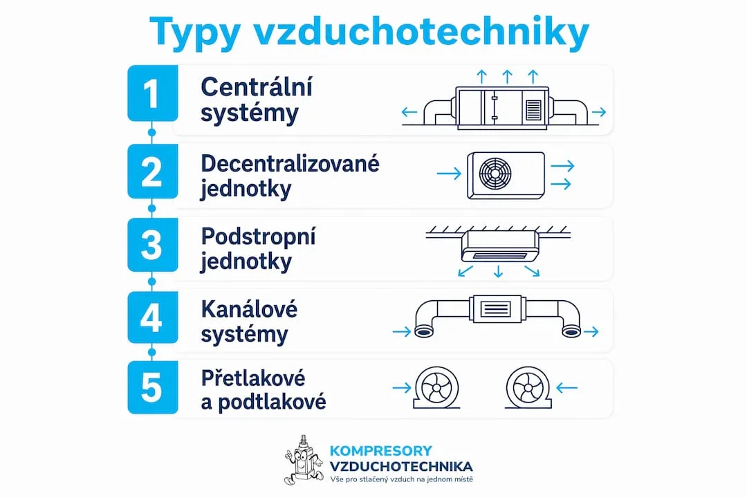
Central air handling systems serve the entire building with a single unit connected to a network of ductwork. They are suitable for new industrial halls, production plants and larger commercial buildings, where the ductwork can be integrated into the building structure.
Decentralised units operate without ductwork and are installed directly into the perimeter wall or window. Decentralised air handling systems allow installation even in spaces without ductwork options, making them suitable for renovations or apartments. For industrial operations, they are suitable where a central solution is not technically or economically feasible.
Ceiling-mounted and duct units combine ventilation with air conditioning or heating and are common in commercial spaces, server rooms and clean operations.
Pressurised and depressurised systems are used in special operations, for example in paint shops or the food industry, where it is necessary to control the direction of air flow and prevent contamination.
What are the consequences of poor ventilation for health and performance?
Insufficient ventilation causes measurable problems. High CO2 concentration reduces the cognitive performance of workers, increases the number of errors and slows down decision-making. Humid air promotes the growth of mould and bacteria on surfaces as well as in building structures.
Workers in poorly ventilated spaces suffer more often from headaches, fatigue, and respiratory problems. Long-term exposure to dust or chemical fumes without adequate ventilation leads to occupational diseases. Besides health impacts, employee turnover and sick leave costs also increase. Investment in ventilation technology therefore pays off not only in energy savings but also in the reduction of these indirect costs.
What standards and regulations govern ventilation technology in buildings?
Czech legislation and European standards set specific requirements for ventilation depending on the type of building and operation. Government Regulation No. 361/2007 Coll. determines the minimum amount of supply air at the workplace. The standard ČSN EN 16798 addresses the energy performance of buildings and requirements for the indoor environment, including ventilation.
For industrial operations, hygienic limits apply for concentrations of pollutants, dust, and temperature of the working environment. These limits are monitored by the Regional Public Health Authority, and failure to comply can lead to fines or closure of the operation. Properly designed and operated ventilation technology meets these requirements automatically and provides the operator with measurable evidence of indoor environment quality.
Kompresory-vzduchotechnika: technical solutions for air systems
Kompresory-vzduchotechnika supplies components and systems for industrial air distribution, from air treatment units through SCR screw compressors to air receivers and accessories. For operations dealing with both ventilation technology and compressed air for pneumatic tools, it is a single supplier with a complete offering.
The technical team at Kompresory-vzduchotechnika will advise on the correct selection of compressors, filters, and distribution components for a specific type of operation. Whether it is a new installation or the modernization of an existing system, the offering includes products for small workshops as well as large industrial plants. Browse the current range at kompresory-vzduchotechnika.cz and find out which components match your operational requirements.
Key findings
Ventilation technology with heat recovery is, for industrial and commercial operations, the most effective way to simultaneously ensure air quality, energy savings, and compliance with legislative requirements.
| Point | Details |
|---|---|
| Energy savings | Recuperation recovers up to 90% of heat from exhaust air. |
| Worker health | Controlled ventilation removes CO2, moisture and dust, reducing sick leave and increasing performance. |
| Regular maintenance | Replacing filters every 3–6 months is a condition for maintaining the system's efficiency. |
| Legislative compliance | Standards ČSN EN 16798 and Government Regulation No. 361/2007 Sb. set binding ventilation limits. |
| Compressors-ventilation systems | Supplies compressors, air treatment units and accessories for industrial air systems. |
Frequently asked questions
Why use ventilation systems instead of opening windows?
Ventilation systems ensure a controlled, filtered air supply independent of weather or user behaviour. At the same time, recuperation recovers heat that would otherwise escape through open windows.
How effective is heat recovery?
Modern heat recovery units achieve efficiencies of up to 90% and allow heating cost savings of up to 85% compared to buildings without controlled ventilation.
How often do filters in ventilation systems need to be replaced?
Filters are generally replaced every 3–6 months depending on operating intensity and manufacturer recommendations. Neglected replacement reduces system efficiency and worsens air quality.
Is ventilation mandatory in industrial buildings?
Yes, Government Regulation No. 361/2007 Coll. and hygiene standards set minimum requirements for workplace ventilation. Failure to comply can lead to sanctions from the Regional Public Health Authority.
Can ventilation be connected to a heat pump?
Yes, integrating ventilation with a heat pump and CO2 sensors enables automated ventilation control and reduces the overall energy consumption of operation.
Recommended
- The importance of compressed air automation in industry - Kompresory-Vzduchotechnika.cz
- How air quality affects performance in industry - Kompresory-Vzduchotechnika.cz
- How to install air handling equipment correctly: a practical procedure - Kompresory-Vzduchotechnika.cz
- List of tasks for compressed air: a guide for technicians - Kompresory-Vzduchotechnika.cz

Air flow meter: what it is and how to choose one
An air flow meter is a measuring instrument that determines the amount or mass of air passing through a pipe or air handling system. In industrial practice, it is a basic tool for monitoring compressed air consumption, detecting leaks, and meeting energy management requirements under ISO 50001. Without accurate flow measurement, it is not possible to reliably control compressor room operation or demonstrate energy savings.
Air flow meters are divided into several main categories:
- Thermal mass (calorimetric) flow meters
- Differential pressure flow meters
- Vortex flow meters
- Turbine flow meters
- Ultrasonic flow meters
- Electromagnetic (inductive) flow meters
- Coriolis flow meters
What physical principles underlie air flow measurement?
Each type of flow meter uses a different physical phenomenon. Understanding these principles makes it easier to select the right device for a specific application.
Heat transfer is the basis of calorimetric flow meters. The device heats one sensor and monitors how the flowing air carries heat away from the heated sensor to the reference sensor. The faster the air flows, the greater the heat transfer. This method directly measures mass flow, so the result does not depend on the temperature or pressure of the air.
Bernoulli's equation is the basis for differential pressure flowmeters. A pressure difference arises before and after the restriction element (orifice, nozzle, or Venturi tube), the magnitude of which corresponds to the flow velocity. This method is widespread and reliable in industry, but requires precise installation and regular inspection.
Vortex frequency drives vortex flowmeters. Vortices form behind a triangular bluff body placed in the pipe, and their frequency is directly proportional to the flow velocity. The accuracy of vortex flowmeters is typically within a low single-digit percentage range, and their service life is good even under demanding conditions.
Key technical parameters of every flowmeter are measurement accuracy, pressure drop, measuring range, and response to flow changes. A lower pressure drop of the flowmeter reduces the energy consumption of the whole system and extends the service life of the compressor.
What types of air flowmeters are available?
| Flowmeter type | Principle | Advantages | Limitations |
|---|---|---|---|
| Thermal mass | Heat transfer | Low pressure drop, measures mass flow | Sensitive to moisture and contaminants |
| Differential pressure | Bernoulli's equation | Robust, industrially proven | Higher pressure loss, precise installation required |
| Vortex | Vortex frequency | Low unit percentage accuracy, good service life | Not suitable for very low flow rates |
| Turbine | Mechanical rotation | Simple design | Higher pressure loss, wear of moving parts |
| Ultrasonic | Acoustic transmission | Non-contact, no pressure loss | Higher purchase price |
| Electromagnetic | Electromagnetic induction | Suitable for conductive media | Not suitable for pure air |
| Coriolis | Coriolis force | Very high accuracy | High price, large dimensions |

Testo 6454 is a compact thermal mass flow meter designed for measuring compressed air directly in the pipeline. It measures flow, pressure, and temperature in a single device and enables data transfer to higher-level systems. It is suitable for industrial facilities where continuous consumption monitoring is required.
CS Instruments GmbH offers compact flow meters for compressed air with a digital display and outputs for remote monitoring. Devices in this series are designed for direct installation in pipelines and meet the requirements for energy audits.
Professional tip: Before purchasing, verify whether the flow meter measures volumetric or mass flow. For energy audits and consumption calculations, mass flow is more accurate because it does not depend on operating pressure or temperature.
How to choose the right air flow meter for industry?
The choice of flow meter depends on several specific application parameters. It does not pay to underestimate any of them.
- Operating pressure and temperature: The device must be rated for the maximum operating pressure of the system. Thermal flow meters operate reliably at pressures common in industrial compressor stations.
- Air cleanliness and humidity: Thermal sensors are sensitive to condensate and oil aerosols. If the air is not sufficiently dry and clean, a differential or vortex flow meter is more suitable. Ignoring humidity and contaminants is one of the most common mistakes when selecting a flow meter.
- Measuring range: The flow meter must cover the entire expected flow range, including peak values. A range that is too small causes sensor overload, while a range that is too large reduces accuracy at low flow rates.
- Pressure drop: Older turbine models have higher pressure drops than modern thermal or vortex sensors. A lower pressure drop means lower energy costs and less load on the compressor.
- Calibration and certification: To meet the requirements of ISO 50001 and energy audits, verifiable calibration of the device is required. Flow meters should have a valid calibration certificate from an accredited laboratory.
- Integration into control systems: Modern flow meters offer digital outputs (4–20 mA, Modbus, M-Bus) for connection to remote monitoring systems and industrial automation.
Investing in a higher-quality flow meter with a lower pressure drop and more accurate measurement pays off through energy savings and more reliable operation. The detailed criteria for selecting an industrial compressor apply similarly to the choice of measuring instruments in the system.
Professional tip: Check the sensor's compatibility with the pipe diameter and the required length of straight pipe section before and after the flow meter. Failure to observe installation distances is the most common cause of inaccurate measurement.
How do air flow meters work in practice?
Air flow meters are used in a wide range of industrial applications. The most common areas include:
- Real-time monitoring of compressed air consumption makes it possible to track how much air each operating node actually consumes. This data forms the basis for energy audits and savings planning.
- Leak detection is one of the most valuable functions of a flow meter. By comparing the flow at the inlet and outlet of the system, leaks that would otherwise remain hidden can be quickly identified. The deployment of flow meters in compressed air systems directly contributes to reducing operating costs. More about eliminating air leaks can be found in a separate guide.
- Energy management according to ISO 50001 requires measurable consumption data. A flow meter with a data output allows automatic logging and reporting without manual readings.
- Production and quality: In processes where product quality depends on precise air dosing (painting, blow molding, pneumatic conveying), a flow meter ensures process repeatability.
Proper installation is a prerequisite for accurate measurement. The flow meter must be positioned on a straight section of pipe, sufficiently far from elbows, valves, and other elements causing turbulence. Regular calibration of the devices is essential to maintain accuracy over time. Without it, measured values may gradually drift and affect operational decisions. The recommended calibration interval depends on the manufacturer and operating conditions, and is usually around one year.
Common mistakes include mounting the flow meter too close behind a pipe elbow, neglecting air conditioning before the sensor, or using the device outside its measuring range. All these situations lead to systematic measurement errors, which only become apparent when compared against billed energy consumption.
Kompresory-vzduchotechnika offers air treatment units suitable for preparing compressed air before measuring sensors. Properly treated air extends the flow meter's service life and ensures accurate results.
Key takeaways
An air flow meter is an essential tool for any industrial compressed air system where energy consumption, process quality, or audit compliance requirements matter.
| Point | Details |
|---|---|
| Measurement type | Thermal flow meters measure mass flow independently of pressure and temperature. |
| Pressure drop | A lower pressure drop of the flow meter reduces energy costs and the load on the compressor. |
| Technology selection | Humidity and contaminants in the air determine the suitable sensor type. |
| Accuracy of vortex devices | Vortex flow meters achieve an accuracy of 0.5–2% with good service life. |
| Calibration | Regular calibration is a prerequisite for reliable data for energy management. |
Frequently asked questions
What is an air flow meter and what is it used for?
An air flow meter is a measuring device that determines the quantity or mass of air passing through a pipeline. It is used for monitoring compressed air consumption, detecting leaks, and meeting energy audit requirements.
How does a thermal air flow meter work?
A thermal flow meter heats one sensor and measures how much heat the flowing air carries away to a reference sensor. The intensity of heat transfer corresponds to the mass flow rate of air, with the result being independent of operating pressure or temperature.
How is air flow measured by a differential flow meter?
A differential flow meter measures the pressure difference before and after a restriction element. According to Bernoulli's equation, there is a direct relationship between the pressure difference and the flow velocity, from which the flow rate is calculated.
How does an inductive flow meter work and is it suitable for air?
An inductive flow meter uses electromagnetic induction and requires an electrically conductive medium. It is not suitable for clean air; its typical applications are liquids, such as water or cooling media.
How to choose an air flow meter for an industrial system?
The choice depends on operating pressure, temperature, air cleanliness, required measuring range, and the method of data integration. Thermal flow meters are suitable for dry and clean air, while differential or vortex devices better tolerate moisture and impurities.
Recommended
- Air flow testing methods: a guide for technicians - Kompresory-Vzduchotechnika.cz
- Why monitor air humidity: a guide to a healthy home - Kompresory-Vzduchotechnika.cz
- Air pressure measurement options: a guide for technicians - Kompresory-Vzduchotechnika.cz
- How a cyclone separator works: a practical guide - Kompresory-Vzduchotechnika.cz

What Does Automatic Air Management Mean: A Guide to Systems
How automatic air control works and why it matters
Automatic air control is a technology that independently regulates the flow, pressure, temperature and quality of air in an enclosed space without the need for manual intervention. The system continuously collects data from sensors, evaluates it according to pre-set control logic and automatically adjusts the operating parameters of ventilation or air-conditioning units. The result is a stable microclimate, lower energy consumption and the elimination of errors caused by the human factor.
Key functions and areas of application of automatic air control:
- Air flow regulation in residential heat recovery units as well as industrial ventilation systems
- Maintaining pressure balance between supply and exhaust air, thereby minimizing heat losses
- Air quality control by measuring CO2, humidity and temperature with automatic switching of operating modes
- Integration with building control systems for coordinating ventilation, heating and fire protection
- Industrial applications ranging from production halls to compressor stations
Expert Libor Štorec from the TZB-info website emphasizes that a correctly set automatic system regulates flows quickly and precisely, which saves technicians time during commissioning. The company Brink Climate Systems has demonstrated that automatic constant flow control maintains pressure balance and maximizes the efficiency of the heat exchanger. Kompresory-vzduchotechnika offers components and expert advice for these systems.
What sensors and data drive automatic air control?
The whole system is based on precise measurement. Without reliable sensors, the control logic has nothing to work with, and the results are then inaccurate or misleading.
The most commonly used types of sensors:
- Temperature sensors monitor the temperature of both supply and exhaust air and respond to fluctuations in real time
- Humidity sensors prevent condensation and mould growth by triggering a dehumidification or ventilation cycle
- CO2 sensors measure carbon dioxide concentration and signal the need for more intensive ventilation
- Pressure sensors monitor differential pressure in the ductwork and detect clogged filters or blocked ducts
- Built-in anemometers measure precise volumetric air flow and allow the system to maintain set values
Data transmission takes place either via analogue signals (0–10 V, 4–20 mA) or digital buses such as Modbus or KNX. The control centre processes the data in real time and activates the corresponding ventilation or shutdown modules. Sensor accuracy directly affects how quickly and reliably the system responds to changes in the space.
Professional tip: Place CO2 sensors at a height of 1.5 m above the floor, as far as possible from the air supply opening. Measurement near the supply opening underestimates the actual concentration in the occupied zone, causing the system to ventilate less than necessary.
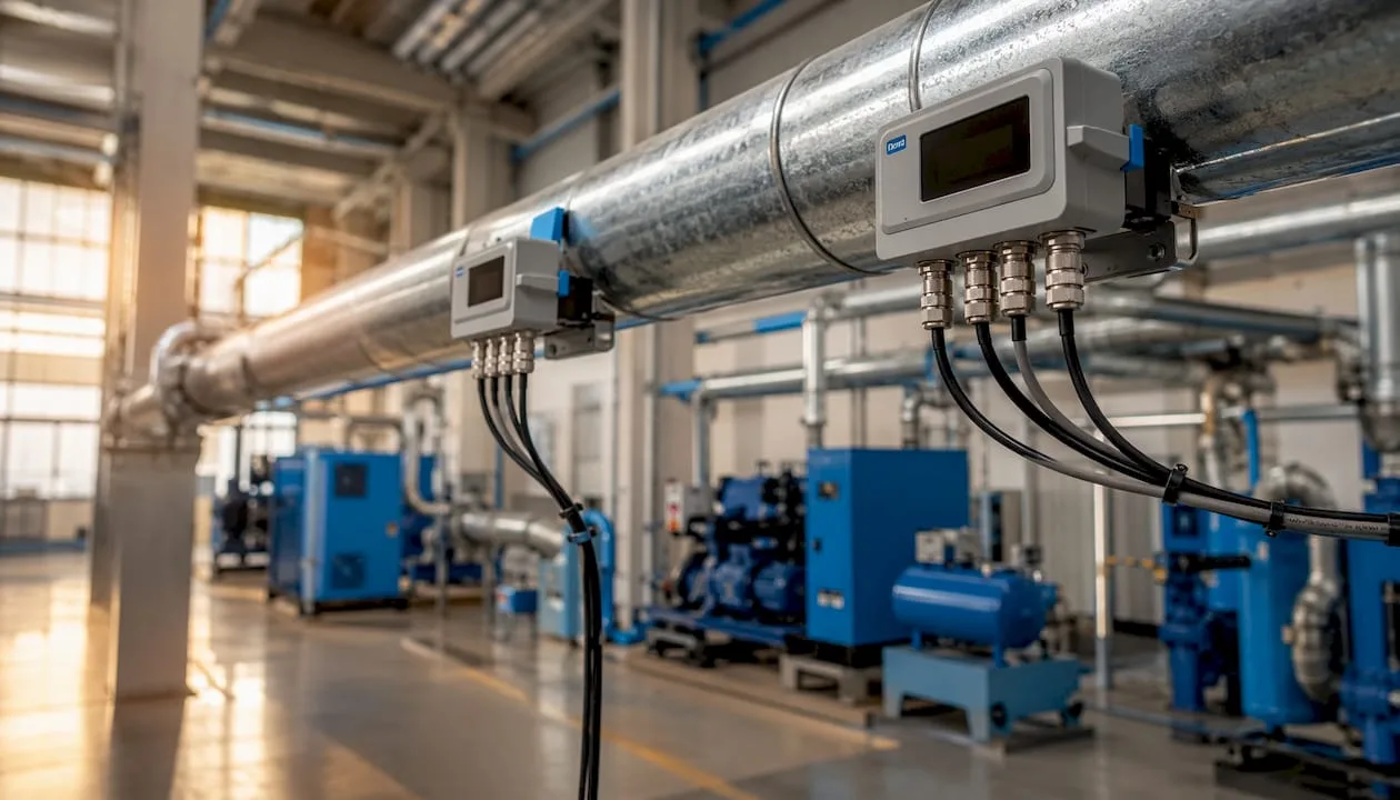
The heat recovery system also prioritizes data from the constant flow sensor over user settings. If the filters are clogged or the ducts are blocked, the system automatically reduces the flow or signals a fault, even if the user has set a higher output.
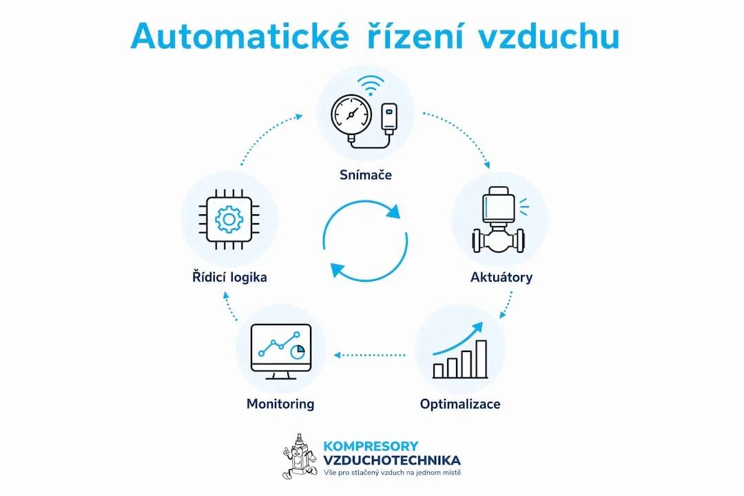
How does control logic automate ventilation systems?
Sensors supply the data, but the control algorithm decides what happens with it. Modern ventilation systems use programmable logic controllers (PLCs) or built-in microcontrollers, which compare the measured values with the set setpoints and issue commands to inverters, dampers or fans.
| Control type | Principle | Typical application |
|---|---|---|
| Constant flow control | Maintains the set air flow regardless of duct resistance | Residential heat recovery units |
| Pressure control | Maintains constant pressure in the duct network | Industrial compressor stations |
| Trim control | Changes the setpoint according to room occupancy | Office buildings, production halls |
| Temperature control | Controls heating or cooling of the supply air | AHU air handling units |
| Humidity control | Activates the humidifier or dehumidifier | Hospitals, sensitive goods warehouses |
Trim control is particularly effective in industrial systems. The system dynamically adjusts the setpoint parameter according to the current occupancy of the space, so it ventilates at a minimum in an empty production hall and switches to maximum output during full operation. The result is demonstrable energy savings without compromising air quality.
System security includes emergency shutdown when temperature limits are exceeded, fire detection, or power failure. The control system then switches to a safe state and blocks restart without technician authorization.
Professional tip: When programming the PLC, set the controller hysteresis to at least 5% of the measured variable's range. Too narrow a hysteresis causes rapid switching of actuators, so-called hunting, which shortens their service life.
What advantages does automatic air control bring in practice?
Automatic air control brings measurable advantages over manual control, both in households and in industrial operations.
Precise flow measurement with a built-in anemometer maintains the set airflow while minimizing electricity consumption. Balanced ventilation, where supply and exhaust air are equalized, prevents condensation on cold surfaces and the formation of mold. Comparative measurements of CO2 and heat losses confirm that apartments with controlled ventilation achieve better air quality and lower energy consumption than spaces ventilated only through windows.
Main benefits of automatic air control:
- Energy savings thanks to optimizing fan speed and airflow according to current need
- Prevention of condensation and mold through balanced ventilation with precise humidity control
- Elimination of the human factor: the system ventilates correctly even when the user forgets to ventilate
- Healthier indoor environment by keeping CO2 concentration below critical levels
- Lower operating costs in irregularly used spaces thanks to demand-controlled regulation
Systems with automatic control provide comfortable microclimate and ecological benefits in modern homes. Automatic ventilation differs from air conditioning: its primary goal is continuous air exchange and humidity control, not cooling the space.
Where is automatic air control actually used?
Automatic air control finds application in a wide range of environments, from family homes to large industrial halls. The specific deployment varies according to the requirements for flow rate, pressure, and air quality.
- Residential heat recovery units (e.g. Brink systems) automatically maintain pressure balance and maximize the efficiency of the heat exchanger, thereby reducing heat losses during ventilation
- Production halls and warehouses use demand-controlled regulation, which adapts ventilation intensity to space occupancy and reduces operating demands in unoccupied zones
- Compressor stations regulate pressure in the pipe network and protect connected tools from pressure surges; pressure regulation in pneumatics is a key element of reliable operation
- Office buildings and schools combine CO2 sensors with a building management system (BMS) to ventilate according to actual occupancy
- Hospitals and clean rooms require precise regulation of overpressure or underpressure to prevent contamination between departments
- Automobiles control not only temperature but also air distribution according to the season, preventing window fogging and increasing driving safety
| Environment | Control type | Main benefit |
|---|---|---|
| Residential heat recovery ventilation | Constant flow | Pressure balance, minimal heat losses |
| Production hall | Trim control | Energy savings at low occupancy |
| Compressor station | Pressure control | Tool protection, stable performance |
| Hospital | Overpressure/vacuum control | Contamination prevention |
| Office | CO2 control | Air quality, worker comfort |
Integration with smart homes takes place via KNX, Modbus protocols or manufacturers' proprietary gateways. The system then coordinates ventilation with heating, shading and fire protection as a single unit. A more detailed look at industrial ventilation shows how these principles are applied in production operations.
How to correctly set up and maintain an automatic air control system?
Correct system setup determines whether it will operate reliably for years, or cause problems from the first month of operation. Sensor calibration, setpoint configuration and regular maintenance are the three pillars of long-term stability.
Recommended procedure for commissioning the system:
- Measure the actual flow rates at all outlets and compare them with the design values before starting up the automation
- Calibrate the sensors against a reference instrument, not just according to the factory calibration
- Set the setpoints for flow rate, temperature and humidity according to the actual use of the space, not according to general recommendations
- Verify the function of the emergency shutdown by simulating a fault condition before handover to operation
- Document the settings in the operating log so that a service technician later knows what to deviate from
Typical setup errors include a controller hysteresis that is too narrow, poor sensor placement, or neglecting calibration after a filter change. Regular filter checks, sensor calibration, and evaluation of operating data extend the system's lifespan and prevent failures before they occur.
Professional tip: After every filter change, check whether the system has correctly re-regulated the flow rates. A new filter has lower resistance than a clogged one, so the flow rates change and the automation must set new operating points.
The role of a professional technician is irreplaceable during initial setup. Automation eliminates errors caused by the human factor during operation, but the setup itself requires expert knowledge of sensor calibration, correct wiring of control elements, and an understanding of the piping network's hydraulics.
What standards and legislation apply to automatic air control in the Czech Republic?
Automatic air control in the Czech Republic is subject to several technical standards and legal regulations that set minimum requirements for air exchange, energy performance, and system safety.
The basic normative framework is formed by ČSN EN 16798 (energy performance of buildings, ventilation of non-residential buildings) and ČSN EN 15251 (input parameters of the indoor environment for the design and assessment of the energy performance of buildings). These standards define the minimum air flow rates per person and per area, and the categories of indoor environment quality, from which the settings of control systems are derived.
Industrial ventilation is governed by Government Regulation No. 361/2007 Coll., which sets out the conditions for health protection at work, including requirements for workplace microclimate. The minimum air exchange rate, permissible CO2 concentrations, and temperature ranges are binding here, not merely recommended.
The energy performance of buildings is governed by Act No. 406/2000 Coll. on Energy Management and implementing Decree No. 264/2020 Coll. Automatic air control is one of the tools by which designers achieve the required building energy performance classes (ENB). Recovery units with automatic flow control contribute to reducing the specific heating demand, which is a monitored parameter in building certification.
The installation of ventilation systems must also comply with ČSN 73 0872 (fire safety of buildings, ventilation equipment) and be coordinated with the building's fire safety design. Automatic dampers and control systems must respond according to a predefined scenario in the event of a fire alarm.
Key takeaways
Automatic air control combines precise measurement, control algorithms, and actuators into a system that ensures optimal air quality, pressure balance, and energy efficiency without manual intervention.
| Point | Details |
|---|---|
| Sensors as the foundation of the system | Temperature, humidity, CO2, pressure and flow are input data for every decision made by the control logic. |
| Pressure balance prevents mold | Balancing supply and exhaust airflow eliminates condensation and the formation of mold on perimeter structures. |
| Trailing control saves energy | Dynamic setpoint adjustment based on room occupancy reduces operational demands in unoccupied zones. |
| Standards are binding | ČSN EN 16798, Government Regulation No. 361/2007 Coll. and Act No. 406/2000 Coll. set the minimum requirements for both design and operation. |
| Calibration determines reliability | Regular sensor calibration and filter inspection are prerequisites for the accurate operation of the automation system. |
Frequently Asked Questions
What exactly does automatic air control mean?
Automatic air control is a system that uses sensors and control algorithms to independently regulate the airflow, pressure, temperature, and humidity in a space without manual user intervention.
How is airflow measured in automatic systems?
Airflow is measured by a built-in anemometer or differential pressure sensor located in the ducting. The measured value is compared with the setpoint, and the fan's inverter automatically adjusts the airflow.
How much air per person do Czech standards require?
ČSN EN 16798 and Government Regulation No. 361/2007 Sb. set minimum airflow rates per person and per room area depending on the category of the space and its use; specific values vary according to the type of building and occupancy.
What does air humidity express and why does the system monitor it?
Relative humidity indicates what percentage of the maximum possible amount of water vapor the air contains at a given temperature. The automatic system monitors it because excessively high humidity promotes mold growth, while low humidity causes the mucous membranes to dry out.
How does air-to-air air conditioning work together with automatic control?
Air-to-air air conditioning transfers heat between the outdoor and indoor air; automatic control coordinates its operation with ventilation to minimize heat losses and maintain the required temperature and humidity in the space.
Recommended
- The importance of compressed air automation in industry - Kompresory-Vzduchotechnika.cz
- List of tasks for compressed air: a guide for technicians - Kompresory-Vzduchotechnika.cz
- Pneumatic systems explained: a guide for technicians - Kompresory-Vzduchotechnika.cz
- The Role of Automation in Pneumatics in Manufacturing Processes - Kompresory-Vzduchotechnika.cz

Noise Reduction in Operation: Methods, Standards and Health Protection
This article is no longer up to date. Please go to the home page or look into our advice centre.

Trends in Pneumatic Systems 2026: An Overview of Innovations
In brief:
- Pneumatic Systems Trends 2026 are linked to the integration of intelligent control, magnetic levitation and the ISO 8573-1 standard. The implementation of these technologies increases efficiency, reduces energy consumption and improves the reliability of production lines. A proper foundation in the form of air quality control and energy-efficient compressors is key to successful modernization.
Trends in pneumatic systems 2026 are defined by three forces: the integration of intelligent control with the IO-Link protocol, magnetic levitation in rodless cylinders, and stricter requirements of the ISO 8573-1 standard for compressed air quality. 35% of new pneumatic products already include built-in condition monitoring. These figures show that intelligent features are ceasing to be an optional extra and becoming an industry standard. Production facilities that ignore these pneumatic innovations in 2026 face a growing disadvantage in both cost and reliability.
How are intelligent control and IoT transforming pneumatic systems?
Pneumatic systems have long been perceived as "black boxes" with no data output. The transition to intelligent nodes with IO-Link fundamentally changes this architecture. Every valve, pressure sensor or flow meter becomes a source of data available to the higher-level control system in real time.

IO-Link is a standardized communication protocol according to the IEC 61131-9 standard. It operates over a standard three-wire cable and does not require a special bus. As a result, its deployment into existing infrastructure is significantly cheaper than switching to industrial Ethernet.
Edge computing complements IO-Link by processing data directly at the source, rather than in a central cloud. Latency drops to milliseconds, enabling an immediate response to pressure or flow deviations. Predictive maintenance thus ceases to be a theory and becomes operational practice.

Intelligent pneumatic systems reduce unplanned downtime by up to 45% and increase overall equipment effectiveness (OEE) by 12%. These figures correspond to experience from production lines, where sensor data detects an air leak or seal wear before it causes a failure.
Specific benefits of intelligent control include:
- Continuous pressure monitoring at every node with automatic alerts when a deviation exceeds the set limit
- Automatic flow correction according to the current demand of the production line without operator intervention
- Digital consumption records for accurate energy billing per individual machine or workstation
- Remote diagnostics via standard industrial interface without the need for a technician's physical presence
Professional tip: When deploying IO-Link, start with pressure monitoring at the most heavily loaded node. Data from one month of operation will show where the biggest losses are and justify the investment in further expansion.
Integration of piezo technology and software goes even further. A single programmable terminal replaces up to 50 individual components, significantly simplifying and reducing the cost of setting up the entire system. This level of consolidation reduces the number of potential failure points and shortens the time needed to reconfigure the line when the production program changes. More on the role of automation in practice is described in the fluid power automation guide.
How does magnetic levitation change rodless cylinders?
Magnetic levitation in rodless cylinders eliminates mechanical contact between the moving member and the cylinder body. The result is zero friction, no seal wear, and significantly higher positioning accuracy. Accuracy reaches ±1 µm, a parameter previously reserved only for electric linear actuators.
The energy aspect is equally convincing. Magnetically levitated cylinders achieve 40% higher energy efficiency compared to conventional pneumatic cylinders. This saving comes from the elimination of friction losses and from the recovery of kinetic energy via supercapacitors integrated into the actuator.
Service life exceeds 100 million cycles, which is 5 to 10 times more than conventional designs. This service life fundamentally changes the economics of component replacement and reduces planned maintenance costs.
| Parameter | Conventional cylinder | Magnetically levitated cylinder |
|---|---|---|
| Positioning accuracy | ±50–100 µm | ±1 µm |
| Energy efficiency | basic level | +40 % |
| Service life (cycles) | 10–20 million | over 100 million |
| Friction | mechanical | zero |
| Energy recovery | no | yes (supercapacitor) |
Implementation of magnetically levitated cylinders requires expertise in both motion control and supercapacitor integration. This is not a simple replacement of a mechanical cylinder. The system integrator must design a control loop capable of handling levitation dynamics while also ensuring safe stopping in the event of a power failure.
Professional tip: Before deploying magnetic levitation, verify the compatibility of the control system with the required dynamics. A standard PLC with a 10 ms cycle time may not be sufficient for applications requiring ±1 µm accuracy at high speeds.
Special designs for demanding environments, for example operation with hydrogen, achieve reliability of 99.999% and a service life 300–400% longer than standard designs. These parameters show where the future of pneumatic systems in energy-intensive industries is heading.
Why is compressed air quality critical in 2026?
ISO 8573-1 defines purity classes for compressed air based on solid particle content, moisture, and oil content. Quality class ISO 8573-1:2010 [1:2:1] is becoming the standard for production facilities with high reliability requirements. Failure to meet these classes causes premature valve wear, nozzle clogging, and product contamination.
The correct selection and installation of FRL units (filter, regulator, lubricator) directly determines whether the system will meet this standard. An incorrect component sequence or undersized components increases pressure losses above 10%, which directly translates into higher compressor energy consumption. Optimal sizing is based on actual flow rates in l/min, not on the nominal values shown on the equipment nameplate.
Correct procedure for selecting and installing FRL units:
- Measure the actual flow rate at the given point in l/min at maximum line load, not just an estimated value.
- Select a filter with a flow coefficient at least 20% higher than the measured value, so that the pressure drop does not exceed 0.1 bar at full flow.
- Install the components in the correct order: filter first, followed by the regulator, with the lubricator last before the consumer.
- Set the regulator to the lowest pressure at which the consumer operates reliably. Every extra bar unnecessarily loads the compressor.
- Monitor the pressure differential across the filter. Exceeding 0.5 bar indicates that the filter element is clogged and needs to be replaced.
The correct order of FRL units significantly affects the service life of the entire system. Many operating technicians underestimate this order and install the automatic lubricator before the regulator, causing oil contamination of the control valve and shortening its service life. Filtration of compressed air according to international standards is described in detail by the ISO 8573 filtration program.
How do modern compressors reduce energy costs?
Screw compressors with permanent magnet motors and variable speed drive (VSD) save 15–20% energy compared to compressors with fixed-speed motors. This saving comes from dynamic adaptation of compressor output according to current demand for compressed air. The compressor does not run at full output when the line only needs 60% of capacity.
Permanent magnet motors have higher efficiency across the entire speed range, not just at a single operating point. This feature is key for operations with variable demand, where a traditional fixed-speed motor works outside the optimal point for most of its operating time.
Benefits of modern compressors with VSD and permanent magnets include:
- Reduction of heat losses in the motor compartment, which reduces demands on plant room air conditioning
- Quieter operation under partial load due to lower speeds of the screw block
- Longer service life of the screw block due to lower peak temperatures under variable load
- Direct integration with intelligent pneumatic systems via IO-Link or industrial Ethernet for central consumption control
Integration of the compressor with an intelligent pneumatic system closes the control loop from the consumer to the source. The control system knows the current demand of each node and passes this information to the compressor, which adjusts output before the pressure in the network drops below the set limit. The result is a more stable network pressure and a lower energy peak at startup. Technical parameters of screw compressors for continuous operation are available directly in the Kompresory-vzduchotechnika catalog.
Key insights
Trends in industrial pneumatics for 2026 require the simultaneous implementation of intelligent control, proper filtration according to ISO 8573-1, and energy-efficient compressors with VSD, so that operations achieve measurable savings as well as higher reliability.
| Point | Details |
|---|---|
| Intelligent control with IO-Link | Reduces unplanned downtime by 45% and increases OEE by 12% thanks to real-time data. |
| Magnetic levitation | Accuracy of ±1 µm and a lifespan of over 100 million cycles are changing the maintenance economics of rodless cylinders. |
| ISO 8573-1 standard | The correct air purity class and the correct order of FRL units prevent pressure losses exceeding 10%. |
| Compressors with VSD | Permanent magnet motors with variable speed save 15–20% energy compared to fixed-speed motors. |
| Condition monitoring | 35% of new pneumatic products feature built-in monitoring, which reduces energy consumption by 25–35%. |
Practical experience: what really works and what doesn't
I have been working with pneumatic systems long enough to see how promising technologies turn into operational reality. Magnetic levitation and IO-Link are genuine shifts, not marketing terms. But deployment without preparation brings problems that manufacturers don't mention in their brochures.
The biggest mistake I see repeatedly is underestimating the quality of compressed air. An operation invests in smart valves with IO-Link and then files a complaint six months later, because nobody changed the filters or checked the humidity class. The ISO 8573-1 standard is not a bureaucratic formality. It is protection for the investment in the entire system.
The second thing that surprises me: compressors with VSD are deployed, but the control system does not communicate with them. The compressor runs autonomously and the smart pneumatic system runs autonomously too. The energy savings, which could be 30%, remain at 10%, because the data connection is missing. Integration is not optional, it is a condition for achieving the declared parameters.
Digital twins of pneumatic systems are another topic where expectations are ahead of reality. The model must be specified with the accuracy required for its use: ±2% for control, ±5% for energy optimization, and ±10% for predictive maintenance. An operation that wants a "digital twin" but does not specify the accuracy will get a tool that does not fulfill any of these purposes well.
The recommendation for 2026 is simple: start from the basics. Measure actual air consumption, check quality according to ISO 8573-1, and only then add the smart layer. The technology works. But only on a solid foundation.
— Zdeněk
Pneumatic components and consultation from Kompresory-vzduchotechnika
Kompresory-vzduchotechnika offers a complete range for modernizing pneumatic distribution systems as well as compressed air treatment. For new distribution systems, push-in system pipes are available in diameters of 15–28 mm, suitable for industrial installations requiring low pressure drops and easy assembly. For air quality treatment according to the ISO 8573-1 standard, Kompresory-vzduchotechnika offers air treatment units up to 10 bar with various filtration levels.
The expert team at Kompresory-vzduchotechnika provides technical consultation when selecting components as well as when designing the entire system. The consultation includes an assessment of the current state of the distribution system, recommendations for filtration class, and sizing of FRL units according to actual flow rates. Contact and technical support are available directly on the Kompresory-vzduchotechnika.cz website.
Frequently asked questions
What are the trends in pneumatic systems 2026?
Key trends include smart control with IO-Link, magnetic levitation in rodless cylinders, stricter requirements of the ISO 8573-1 standard, and compressors with VSD drives. Together, these technologies reduce energy consumption and increase the reliability of production lines.
How does IO-Link reduce pneumatic operating costs?
IO-Link enables continuous real-time monitoring of every node and predictive maintenance. Smart systems with IO-Link reduce unplanned downtime by up to 45% and increase overall equipment effectiveness by 12%.
What is the service life of magnetically levitated cylinders?
Magnetically levitated rodless cylinders achieve a service life of over 100 million cycles, which is 5 to 10 times more than conventional designs. Eliminating friction removes the main cause of wear in standard pneumatic cylinders.
Why is the ISO 8573-1 standard important for selecting FRL units?
ISO 8573-1 defines compressed air purity classes that a system must meet for reliable operation. Properly sized and sequenced FRL units prevent pressure losses exceeding 10% and protect valves and consumers from contamination.
How much energy does a compressor with VSD save compared to a standard one?
Screw compressors with permanent magnet motors and VSD drive save 15–20% energy compared to compressors with fixed-speed motors. The savings are highest in operations with variable compressed air demand.
Recommended
- Pneumatic tools in 2025: trends and innovations - Kompresory-Vzduchotechnika.cz
- How pneumatics works: a complete guide for industry 2026
- Overview of pneumatic valve applications in industry 2026 - Kompresory-Vzduchotechnika.cz
- Why use pneumatics: efficiency, speed and safety - Kompresory-Vzduchotechnika.cz

How to properly ventilate a compressor room: a guide for technicians
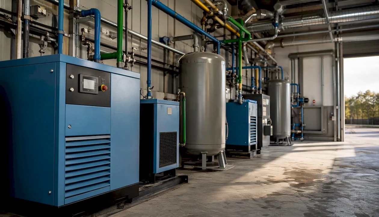
In brief:
- Proper ventilation of the compressor room maintains a temperature of 18–27 °C and humidity of 40–60%, which is key for the long service life of the equipment. Inadequate climate control leads to overheating, corrosion and higher energy consumption. Correct placement of openings, fan selection and regular maintenance are essential for efficient operation.
Proper ventilation of the compressor room is defined as the controlled supply of fresh air and removal of heat so that the room temperature stays within the range of 18–27 °C and the relative humidity at a level of 40–60%. These parameters directly determine how efficiently the compressor works and how long it lasts without a serious failure. Overheated or humid air shortens the service life of filters, oils and mechanical components. Technicians who underestimate ventilation end up dealing with costly repairs where it would have been enough to properly design the air paths from the start. This guide describes specific technical measures that ensure stable and reliable operation of the compressor room.
How to properly ventilate a compressor room: optimal climatic conditions
The temperature in the compressor room must stay within the range of 18–27 °C and the humidity at 40–60%. These values are not indicative recommendations; they are operating limits whose exceeding has a direct impact on the performance and wear of the equipment.
Exceeding the upper temperature limit increases the compressor's power consumption, because the machine has to compress warmer and less dense air. The result is higher energy consumption at lower output. Conversely, too low a temperature, especially during the winter months, causes moisture condensation inside the air tank and piping, which accelerates corrosion.
Humidity above 60% accelerates the degradation of compressor oil and shortens the service life of air filters. Cleanliness and climate stability significantly affect the service life of filters and components. A filter clogged with moisture and impurities increases the pressure drop, which directly translates into higher energy consumption.
A stable environment in the compressor room is not a luxury. It is a basic condition for the equipment to work according to the manufacturer's specifications and for service intervals to correspond to the planned schedule.
Impacts of an unstable environment on operation
- Temperature above 27 °C: higher power consumption, risk of compressor thermal protection, shortened oil service life
- Temperature below 18 °C: moisture condensation, corrosion of the air tank and piping, starting problems in frost
- Humidity above 60%: faster filter clogging, oil degradation, corrosion of internal components
- Humidity below 40%: increased risk of electrostatic discharge for sensitive control units
How to ensure proper air flow in the compressor room?
Proper air flow in the compressor room depends on the placement of the intake and exhaust openings. Intake openings positioned low draw in cooler air near the floor, while exhaust openings positioned high remove heated air outside. This arrangement takes advantage of the natural physical properties of air and minimizes the energy demands of ventilation.
A key problem is flow short-circuiting. This occurs when the intake and exhaust openings are located close to each other or on the same side of the building. The compressor then draws in air that has just been heated and expelled. Underestimating flow short-circuiting leads to the intake of heated air and reduces the efficiency of the entire system.
The exhaust ductwork must be as short as possible, with a minimum number of bends. Each 90° bend increases the pressure drop that the fan must overcome. If the length of the exhaust ductwork exceeds several meters, the fan's output must be recalculated to cover the resulting resistance.
Professional tip: When renovating an existing compressor room, first visualize the air flow using a smoke test or thermal imaging. This will reveal locations where warm air accumulates, allowing you to design modifications with minimal structural intervention.
Principles for proper placement of openings
- Intake openings: place at the lowest possible height, ideally 0.3–0.5 m above the floor, on the side facing away from the exhaust
- Exhaust openings: place as high as possible, preferably under the roof or at roof level
- Distance between the intake and exhaust openings: as large as possible, ideally on opposite sides of the room
- Protective grilles: fit with filter inserts to prevent dust and insects from entering
- Check valves on the exhaust: prevent the backflow of cold air in winter when the fan is shut down
What type of fan should you choose for ventilating a compressor room?
The choice of fan depends on the nature of the air ducting. Axial fans are suitable for open spaces with low pressure resistance, while radial fans are suitable for ducting systems where air has to travel longer distances and pass through more fittings. Mixing up these two types leads to under-sizing or over-sizing the ventilation.
An axial fan installed directly in a wall opening is the simplest and cheapest solution. It works reliably where the exhaust opening leads directly outside without ducting. As soon as the air needs to be routed through ducting longer than 1–2 m or through several bends, an axial fan is not sufficient and a radial design must be used instead.
Fans with an alarm output are essential in continuous 24/7 operation. The alarm output signals motor failure or bearing overheating before ventilation failure occurs and the compressor subsequently overheats. This function is standard in industrial installations and should not be missing even in smaller operations with continuous running.

Professional tip: Always size the ventilation for the maximum expected summer temperature, not the annual average. Under-sizing the ventilation leads to inefficient cooling precisely when the thermal load is highest.
Comparison of axial and radial fans
| Parameter | Axial fan | Radial fan |
|---|---|---|
| Pressure resistance | Low | High |
| Suitable use | Wall opening, short run | Ducting system, longer run |
| Noise level | Lower | Higher |
| Acquisition costs | Lower | Higher |
| Alarm output | Optional | Standard on industrial types |
Implementation and maintenance of the ventilation system in the compressor room
A properly designed ventilation system requires regular maintenance, otherwise its performance gradually declines. Overpressure in the room and poor ventilation maintenance increase operating costs and the risk of equipment damage. The maintenance plan must be part of the compressor room's operational documentation from the first day of operation.
Procedure for installing or modifying ventilation:
- Heat load calculation: Add up the power input of all compressors and other heat sources in the room. The result determines the minimum required air flow capacity of the ventilation in m³/h.
- Opening placement design: Mark the position of the intake and exhaust openings on the floor plan. Verify that the distance between them is maximum and that there is no risk of flow short-circuiting.
- Fan selection: Based on the length and shaping of the exhaust ducting, choose an axial or radial type. Add a capacity reserve of at least 20% for summer operation.
- Sensor installation: Place temperature and humidity sensors in the center of the room, outside the direct reach of the compressor's intake opening. A sensor placed in a stream of cold air gives distorted readings.
- Control setup: Connect the sensors to the fan controller. Set the fan's activation temperature so that it starts before the temperature exceeds 25 °C.
- Regular filter cleaning: Clean or replace the filters on the intake openings according to the manufacturer's instructions, but at least every three months. A clogged filter reduces air flow and increases pressure resistance.
- Flow inspection: Once a year, check the actual air flow with an anemometer. A drop in flow below the designed value indicates clogged filters or a fan malfunction.
- Value logging: Keep an operating log with monthly records of temperature, humidity, and filter condition. A rising temperature trend at the same ventilation setting will warn of a problem before it manifests as a failure.
Regular diagnostics of the compressor room, including checking the ventilation system, is the most reliable way to prevent unplanned downtime.
Typical ventilation mistakes in compressor rooms and how to avoid them
Improper placement of intake and exhaust openings is the most common cause of compressor room overheating. Technicians make this mistake during renovations, when they rely on existing structural openings instead of designing a new layout based on the physical principles of air flow.
Lack of regular inspections and monitoring continuously reduces system reliability. Neglected ventilation does not show up immediately. The room temperature rises gradually, the compressor switches into thermal protection more and more often, and only then does the technician find out that the filters have not been cleaned for a year and a half.
Overview of the most common mistakes:
- Flow short-circuit: intake and exhaust openings on the same wall or too close to each other; solution: relocate one of the openings or install directional deflectors
- Undersized fan: the fan output corresponds to the average temperature, not the summer maximum; solution: recalculate and replace with a stronger type or add a second fan
- Missing filters on intake openings: dust and dirt settle on the compressor's cooling fins; solution: fit filter inserts of class G3 or G4
- Absence of an alarm system: a fan failure goes unnoticed until the compressor overheats; solution: install a fan with an alarm output or add a temperature alarm
- Incorrect sensor placement: a sensor in the cold air stream shows a lower temperature than the actual room temperature; solution: relocate the sensor to the center of the space
An overview of the most common mistakes in compressor operation shows that ventilation is one of the three most frequently underestimated areas.
Key findings
Proper ventilation of the compressor room requires a combination of correctly placed openings, a correctly sized fan, and regular maintenance, and neglecting any one of these three elements leads to overheating and a shortened service life of the equipment.
| Point | Details |
|---|---|
| Temperature and humidity range | Maintain a temperature of 18–27 °C and humidity of 40–60% for optimal compressor operation. |
| Opening placement | Place intake openings low, exhaust openings high, and on the opposite side of the room. |
| Fan selection | Axial type for direct wall openings, radial for duct systems with higher resistance. |
| Sizing for maximum conditions | Design ventilation for the summer temperature peak, not for the average annual temperature. |
| Regular maintenance | Clean filters at least every three months and keep an operating log with measured values. |
Practical experience: what really determines ventilation quality
Over years of working with compressor rooms of various sizes, I have found that the biggest problems do not arise from a lack of knowledge of principles, but from compromises made during implementation. The technician knows that the intake opening should be low, but the builder says there is a load-bearing wall there. The result is an opening at the wrong height and a compressor that overheats in July.
The second thing that repeatedly surprises me is the absence of monitoring. A compressor room without a temperature alarm is like a car without an oil warning light. You keep driving until it breaks down. Installing a simple temperature sensor with an alarm costs a fraction of the price of a single compressor repair after overheating.
Personally, I recommend taking a thermal image of the compressor room after the first summer of operation with every new installation or reconstruction. A thermal camera shows exactly where warm air accumulates and where airflow is insufficient. This information is more valuable than any desk-based calculation. The correct basic requirements for a compressor room are a foundation, but operational reality always brings details that no manual covers.
— Zdeněk
Compressors and expert support from Kompresory-vzduchotechnika
A well-designed compressor room ventilation system only makes sense if it is backed by a reliable compressor. Kompresory-vzduchotechnika offers SCR screw compressors for industrial operations, where the demands for stable temperature and continuous operation are highest.
The Kompresory-vzduchotechnika team provides technical consultations on equipment selection as well as on the design of the compressor room ventilation system. If you are dealing with the reconstruction of an existing compressor room or planning a new installation, our expert support includes an assessment of the spatial conditions, fan recommendations, and a review of the project documentation. Contact us directly through the website and describe your operation. We will respond with specific technical recommendations, not a generic offer.
Frequently Asked Questions
What is the optimal temperature for a compressor room?
The optimal temperature in a compressor room is 18–27 °C. Exceeding the upper limit increases the compressor's power input and shortens the oil's service life.
How to prevent air short-circuiting?
Place the intake and exhaust openings on opposite sides of the room and as far apart as possible. Airflow short-circuiting occurs when the compressor draws in air that has just been blown out.
When should a radial fan be chosen instead of an axial one?
Choose a radial fan whenever the exhaust ducting exceeds a length of 1–2 m or includes multiple bends. An axial fan will not achieve the required airflow in such a system.
How often should the filters on the compressor room intake openings be cleaned?
Clean or replace the filters at least every three months. In dusty environments, shorten the interval to six weeks and monitor the pressure drop across the filter as an indicator of clogging.
Why is temperature monitoring in the compressor room necessary?
A temperature alarm detects a fan failure or filter clogging before the compressor goes into thermal protection. Without monitoring, you will only discover the problem during an unplanned shutdown.
Recommended
- Basic requirements for a compressor room: guide 2026 - Kompresory-Vzduchotechnika.cz
- Checklist of accessories for compressors: a guide for technicians - Kompresory-Vzduchotechnika.cz
- The significance of the compression stage: a guide for technicians - Kompresory-Vzduchotechnika.cz
- Compressor bleeding procedure: a guide for technicians - Kompresory-Vzduchotechnika.cz

Home use of compressors: possibilities and how to choose the right one
In short:
- A compressor for home use makes various jobs easier, from inflating tyres to spray-painting furniture. Choosing the right model depends on the free air delivery, the air tank volume and the type of lubrication. Quiet oil-free compressors with a capacity of around 150–200 l/min and a 50-litre air tank are suitable for most household tasks.
A home-use compressor is a device that covers dozens of practical tasks, from inflating tyres to dust removal to spray-painting furniture. The right choice depends on three key parameters: free air delivery, air tank volume and type of lubrication. Modern home compressors are designed for simple operation without the need for professional training. Home use of compressors offers possibilities that were previously reserved exclusively for professional workshops. Choosing the right model determines the efficiency, noise level and overall service life of the equipment.
1. What types of compressors are suitable for home use?
The basic division of compressors for home use is into oiled and oil-free types. Each type has different maintenance requirements and is suited to different situations.
Oil-free compressors are the first choice for beginners. Oil-free compressors require minimal servicing and eliminate the risk of oil leaking into the compressed air. This is an advantage especially when spray-painting or working with food. The purchase price is lower and operation is simple.
Oiled compressors can handle more demanding and longer-lasting jobs. They have a longer service life under intensive operation and lower noise levels compared to equivalent oil-free models. However, they require regular oil changes and level checks.
- Oil-free compressor: suitable for inflating, cleaning, occasional spray-painting
- Oiled compressor: suitable for pneumatic tools, longer working cycles, renovations
- Piston compressor: the most widespread type for home workshops
- Screw compressor: quiet and powerful, but more expensive
Professional tip: If you plan to use the compressor less than once a week for lighter jobs, an oil-free model will save you time on maintenance and money on servicing.
2. Practical uses of a compressor at home and in the garden
Home compressors are used for tyre maintenance, dust cleaning, furniture renovation with pneumatic tools, and garden care. Each of these applications has different requirements for pressure and air flow.
Inflating
Inflating tyres on a car, bicycle, garden tractor, or inflatable mattresses is one of the most common household tasks. Car tyres require a pressure of approximately 2.0–2.5 bar, while sports bicycle tyres require up to 8 bar. A compressor can do this job in a fraction of the time compared to a hand pump.
Dust cleaning and dirt removal
Compressed air cleans air conditioning filters, computer cases, garden tools, or gaps in paving. A blow gun with a pressure of 3–6 bar removes dust from places a brush cannot reach. This application saves time during regular workshop or garage maintenance.
Pneumatic tools for renovation and maintenance
- Pneumatic drill and screwdriver: faster and lighter than electric alternatives
- Pneumatic sander: ideal for sanding car bodywork or furniture
- Nail gun: flooring installation, cladding, carpentry work
- Pneumatic nut gun: wheel changes or chassis repairs
Spray painting and lacquering
Spray painting requires a pressure of 30–50 PSI (approximately 2–3.5 bar) and a steady air flow. A spray gun applies paint more evenly than a brush and significantly speeds up the work. For painting furniture or fences, a compressor with an air tank volume of at least 50 litres is essential.
3. How to choose the right compressor power and parameters
Compressor performance is indicated by free air delivery in litres per minute (l/min) and maximum pressure in bar. These two values determine which tools and applications the compressor can handle.
Household tasks require a free air delivery between 80 and 270 l/min. Hobby models up to 150 l/min can handle basic tasks such as inflating or cleaning. For pneumatic tools or painting, a delivery of at least 180–200 l/min is required.
| Application | Required pressure | Recommended flow |
|---|---|---|
| Inflating tyres | 7–10 bar (100–150 PSI) | 30–50 l/min |
| Spray painting | 2–3.5 bar (30–50 PSI) | 100–200 l/min |
| Nail gun | 5–6 bar (70–90 PSI) | 30–60 l/min |
| Pneumatic grinder | 6–7 bar | 150–250 l/min |
| Dust blowing | 3–6 bar | 20–40 l/min |
The recommended air tank volume is at least 50 litres for efficient operation of home compressors. A larger air tank means longer working cycles without having to wait for the pressure to build back up. For occasional inflating, 24 litres is enough; for painting or pneumatic tools, 50–100 litres is the right choice.
A compressor output with a reserve of at least 50% above current needs prevents overload and extends the service life of the equipment. So if the tool consumes 100 l/min, choose a compressor with an output of at least 150 l/min.
Professional tip: When choosing, always consider that you'll add more tools in the future. A compressor with a power reserve will pay off more than a model „sized exactly" to today's needs.
A detailed overview of selection factors can be found in the compressor selection guide on the Kompresory-vzduchotechnika blog.
4. Practical tips for operation and maintenance of a home compressor
Proper operation extends the life of the compressor and prevents unnecessary repairs. Most problems arise from neglecting simple regular tasks.
-
Drain condensate after each use. Regular condensate draining prevents corrosion of the pressure tank and increases operational safety. Open the drain valve at the bottom of the air tank until all the water has drained out.
-
Never turn off the compressor by unplugging it. Always turn off the compressor using the switch on the pressure switch. Unplugging under load damages the motor and increases the risk of injury.
-
Seal accessory threads with PTFE tape. Missing thread sealing with PTFE tape is the most common cause of air leaks. Leaks increase noise, waste energy, and shorten the compressor's lifespan.
-
Check the oil level on oil-lubricated models. Check the oil level before each extended use. Operating without sufficient oil will cause irreversible damage to the compressor.
-
Clean the air filter regularly. A clogged filter reduces performance and causes overheating. Clean or replace the filter according to the manufacturer's instructions, typically every 50–100 hours of operation.
-
Store the compressor in a dry, frost-free place. Moisture and frost damage seals and metal parts. A garage or dry workshop are ideal storage locations.
An overview of the most common operating mistakes can be found in the article mistakes when using compressors on the Kompresory-vzduchotechnika blog.
5. Benefits of quiet compressors for home use
Silent compressors significantly expand the possibilities of working at home. Some models operate below 50 dB, which corresponds to the volume of a normal conversation. This allows work in an apartment, near neighbours, or during evening hours.
| Compressor type | Typical noise level | Suitable location |
|---|---|---|
| Standard piston | 70–85 dB | Outdoor workshop, garage |
| Silent oil-free | 45–60 dB | Apartment, living room |
| Silent oil-lubricated | 50–65 dB | Workshop in the house, cellar |
Anti-vibration pads and adequate ventilation extend the compressor's service life and further reduce noise during operation. Placing the compressor on an anti-vibration pad prevents the transmission of vibrations to the floor and surrounding walls. The requirements for correctly positioning a compressor in a household are described in the compressor room guide on the Kompresory-vzduchotechnika blog.
Quiet compressors are particularly advantageous for apartments and family houses, where noisy operation would disturb others. Their purchase price is higher, but the comfort of everyday use justifies this investment.
Key findings
The right choice of compressor for a household depends on a combination of intake capacity, air tank volume, and lubrication type, with oil-free models offering 150–200 l/min capacity and a 50-liter air tank covering most household needs.
| Point | Details |
|---|---|
| Compressor type | Oil-free models are suitable for beginners and occasional work, while oil-lubricated models are suitable for more demanding operation. |
| Capacity and air tank | An intake capacity of 150–200 l/min and an air tank of at least 50 liters will cover both painting and pneumatic tools. |
| Capacity reserve | Choose a compressor with a capacity at least 50% higher than the current needs of your tools. |
| Regular maintenance | Drain the condensate after each use and seal threads with PTFE tape to prevent leaks. |
| Quiet models | Compressors below 50 dB allow working in an apartment or in the evening without disturbing those around you. |
Practical experience: what you won't find in the manuals
The most common mistake I see with home users is underestimating the power needed. They buy a compressor "just for inflating tires" and then find out they want to paint a fence or sand a car body. The result is an overloaded machine that overheats and ends up in the repair shop after two seasons.
The second thing that surprises me is ignoring the condensate. People turn on the compressor, use it, and put it away. Water in the tank then corrodes the metal from the inside. An air tank that would last twenty years ends up lasting five. Yet it only takes opening the valve for thirty seconds after each use.
I also recommend not underestimating the noise level. If you're working in a garage next to a living space or in an apartment, a standard piston compressor will stop being fun very quickly. A quiet model at a higher price pays off because you'll actually use it instead of putting it aside because of the noise.
And one last thing: accessories determine the result just as much as the compressor itself. A quality spray gun, a properly sized hose, and an air purifier turn an average compressor into a reliable tool. A cheap gun will ruin even the best paint.
— Zdeněk
Compressors for home use from Kompresory-vzduchotechnika
Kompresory-vzduchotechnika offers compressors for home use, from compact oil-free models to more powerful oil-lubricated machines suitable for renovations and pneumatic tools. The range also includes accessories for air treatment that ensure clean and dry air for both painting and fine work.
For painting and surface cleaning, our range includes spray and blow guns of various power classes. Proper compressor operation also requires air treatment units, which remove moisture and impurities from the compressed air. The Kompresory-vzduchotechnika team provides technical advice both when choosing and after purchasing the equipment.
Frequently Asked Questions
Which compressor is best for home use?
An oil-free piston compressor with an air tank volume of 24–50 litres and a free air delivery of 100–150 l/min will cover most household tasks. For more demanding work such as painting or pneumatic tools, a model with an output of at least 180 l/min is recommended.
How often should the condensate be drained from the compressor?
Drain the condensate after every use of the compressor. Regular draining prevents corrosion of the air receiver and extends the service life of the equipment.
How many bars do I need for inflating tyres?
Inflating a car's tyres requires a pressure of 7–10 bar (100–150 PSI). Most home compressors can easily reach this pressure.
Are quiet compressors suitable for a flat?
Quiet compressors operating below 50 dB are suitable for use in a flat or near living areas. Their noise level corresponds to normal conversation and won't disturb neighbours even during evening work.
How do I know if a compressor has sufficient power?
A compressor has sufficient power if its free air delivery exceeds the tool's consumption by at least 50%. If the compressor motor runs continuously without pausing, the equipment is overloaded and a more powerful model should be chosen.
Recommended
- Examples of compressor use: a guide for the workshop and production - Kompresory-Vzduchotechnika.cz
- Factors for selecting an industrial compressor: a 2026 guide - Kompresory-Vzduchotechnika.cz
- List of small compressors and their benefits for workshop and construction site - Kompresory-Vzduchotechnika.cz
- Basic requirements for a compressor room: guide 2026 - Kompresory-Vzduchotechnika.cz

List of the Best Compressors 2026: A Selection Guide
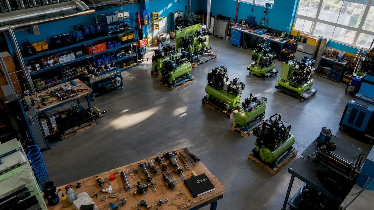
In brief:
- The best compressor for 2026 matches performance, lubrication type, and air receiver volume according to the application.
- For home use, oil-free models with low noise levels and simple maintenance are suitable, while for industry, screw compressors with greater capacity apply.
The best compressor for 2026 is the one that precisely matches the required performance, lubrication type, and air receiver volume. The performance range spans from 1.5 kW for home use up to 55 kW and more for industrial operations, with the air receiver volume determining pressure stability and the number of motor starts. The key difference between oil-lubricated and oil-free models lies in the cleanliness of the output air and maintenance requirements. This list of the best compressors for 2026 covers all main categories from home use through workshop to industry, so that every user finds a model matching their needs.
1. How to choose a compressor for home and hobby use
Oil-free compressors with a power of 1.5–3.7 kW are the best choice for home users and hobbyists. They handle tire inflation, painting small areas, air cleaning, and powering pneumatic tools for small jobs. An air receiver with a volume of 50–100 l is sufficient for intermittent operation typical of a home workshop.
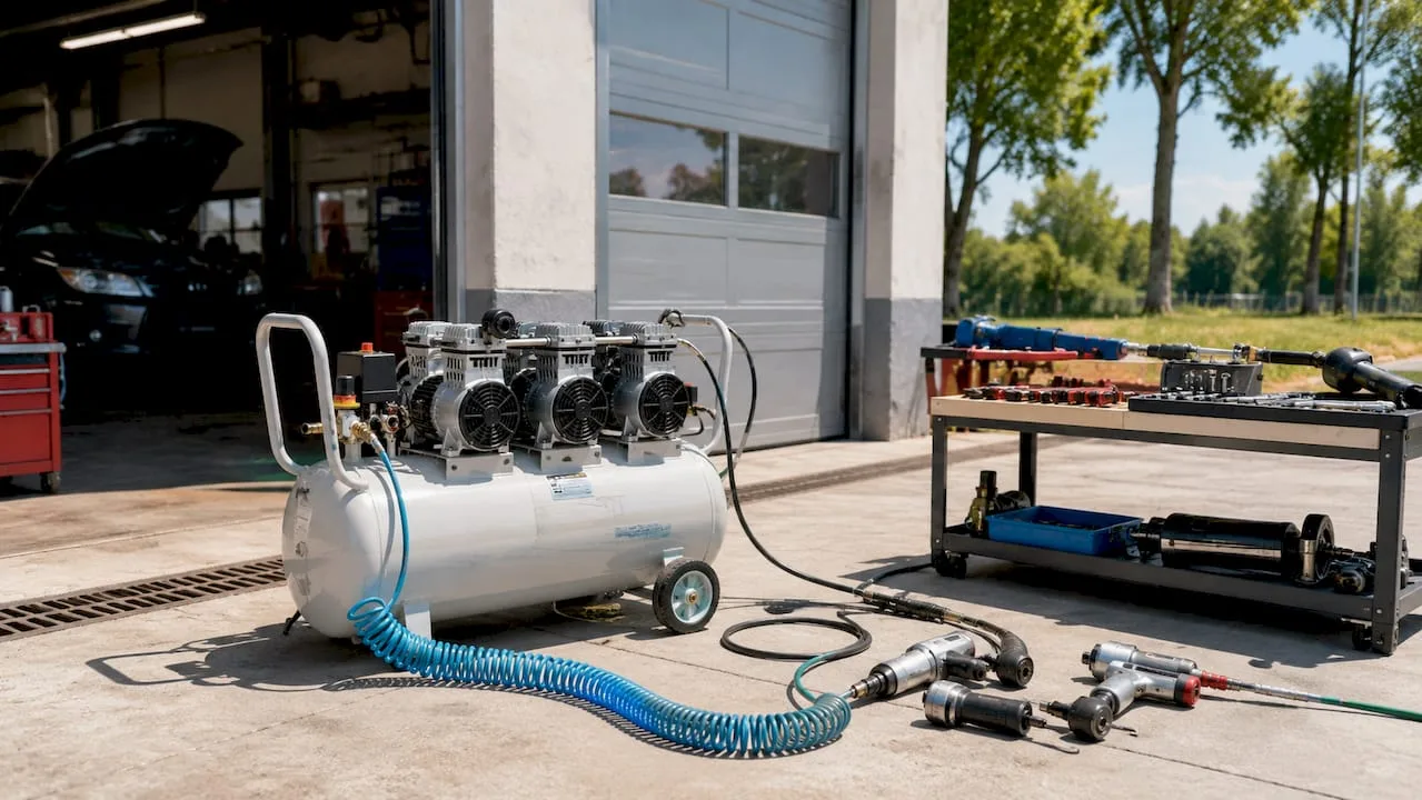
Modern home models offer digital control and automatic shutdown once the set pressure is reached. This function reduces energy consumption and protects the motor from overload. With an intake capacity in the range of 36.5–528 l/min and a maximum pressure of up to 8 bar, oil-free models cover the vast majority of household tasks.
Advantages of an oil-free compressor for home use:
- No oil changes or risk of output air contamination
- Lower noise level compared to oil-lubricated piston models
- Compact dimensions and low weight for easy relocation
- Minimal maintenance requirements, suitable for irregular use
- Quick start-up without the need for warming up
Professional tip: Before buying, check whether the manufacturer states the actual intake capacity (l/min) and not just the theoretical one. The difference is often significant and directly affects which tools the compressor can handle.
2. Best compressors for workshops and small to medium-sized operations
Workshops and small operations require compressors with an output of 5.5–11 kW as the standard. This power range covers the simultaneous operation of multiple pneumatic tools, such as grinders, screwdrivers, or spray guns. An air tank with a volume of 200–500 l ensures stable operating pressure and reduces the number of motor starts, thereby extending its service life.
A piston compressor is cheaper to purchase and suitable for intermittent operation. A screw compressor operates quietly, continuously, and with higher energy efficiency under continuous load. For a workshop with an eight-hour working day and multiple users, a screw model is more economically advantageous.
Key parameters for choosing a workshop compressor:
- Motor output of 5.5–11 kW depending on the number of connected tools
- Air tank of 200–500 l for stable pressure without interruptions
- Type of lubrication according to application: oil-lubricated for workshops, oil-free for painting
- Maximum working pressure of 8–10 bar for standard pneumatic tools
- Noise level below 70 dB for a comfortable working environment
Regular maintenance includes checking the oil, replacing air filters, and detecting air leaks. Neglecting these steps leads to loss of performance and higher operating costs. Oil-lubricated compressors generally require an oil change every 500 operating hours.
Professional tip: The most common mistake in workshops is underestimating the required air tank volume. If the compressor starts more than twice per minute, the air tank is too small. Add an additional pressure vessel instead of replacing the entire compressor.
3. Industrial compressors: screw technology for stable production
Industrial operations require compressors with an output of 15–55 kW and air tanks with a volume of 1,000 l or more for continuous operation. Screw technology is the standard in this segment thanks to its low noise level, high reliability, and energy efficiency under continuous load. Proper sizing of an industrial compressor significantly reduces operating costs and production downtime.
Modern industrial compressors are equipped with digital control systems featuring automatic pressure regulation and remote performance monitoring. Leaks in compressed air distribution systems can increase energy consumption by up to 20%. Regular diagnostics and leak detection are therefore economically essential.
| Operation category | Compressor output | Air tank volume | Recommended type |
|---|---|---|---|
| Small operation / workshop | 1.5–5.5 kW | 50–200 l | Oil-lubricated piston |
| Medium operation | 5.5–15 kW | 200–500 l | Piston or screw |
| Large industrial plant | 15–55 kW | 500–1,000 l | Oil-lubricated screw |
| Continuous production | over 55 kW | over 1,000 l | Screw, possibly oil-free |
Installing a compressor requires a suitable environment with sufficient ventilation, stable temperature, and protection from dust. An unsuitable environment shortens the compressor's lifespan and increases service costs. Industrial operations should plan regular diagnostics at least once a year.
Professional tip: A powerful compressor without a suitable air receiver volume and the right accessories will not ensure optimal operation. Filters, condensate separators and air treatment units are just as important as the compressor itself.
4. Oil-free vs. oil-lubricated compressors: which to choose in 2026
Oil-free compressors are the standard in industries requiring high air purity, such as painting, the food industry, or healthcare. They eliminate the risk of oil particles being carried into the output air, which is a requirement for certified processes. For clean applications, an oil-free compressor with quality condensate separation is the only correct choice.
Oil-lubricated compressors have a longer bearing lifespan and a lower purchase price for comparable output. They require regular oil changes and lubricant level checks, but their operating costs, with proper maintenance, are lower than those of oil-free models. For workshops and industrial operations without air purity requirements, oil-lubricated compressors remain the more economically advantageous choice.
| Parameter | Oil-free compressor | Oil-lubricated compressor |
|---|---|---|
| Cleanliness of the output air | High, no oil particles | Standard, requires filtration |
| Bearing lifespan | Shorter | Longer |
| Maintenance | Lower lubrication requirements | Regular change of oil |
| Noise level | Generally lower | Higher for piston models |
| Purchase price | Higher | Lower |
| Suitable applications | Painting, food industry, healthcare | Workshops, construction, industry |
The choice between the two types depends on the specific application. If the production process requires air purity certification or you work with food, an oil-free compressor is not an optional alternative. For other operations, the decision is based on the ratio of purchase price, operating costs, and required service life.
5. Duty cycle and its impact on model selection
The duty cycle of a compressor indicates how large a portion of the operating time the machine actually works. Piston compressors typically have a duty cycle of 50–70%, while screw compressors operate at 100% load without interruption. Failure to respect the duty cycle leads to motor overheating and premature wear.
For intermittent operation in a home workshop or seasonal use, a piston compressor with a 50% duty cycle is sufficient. Operations with continuous air consumption, such as production lines or auto repair shops with multiple workstations, require a screw compressor with a 100% duty cycle. Correctly matching the compressor to the duty cycle extends the machine's lifespan and reduces repair costs.
6. Accessories and compressed air distribution
Even a powerful compressor cannot ensure reliable operation without the proper accessories. Filters, pressure regulators, condensate separators, and automatic lubricators form the foundation of every functional compressed air system. Quality compressed air distribution made of aluminum or steel pipes minimizes pressure losses and leaks.
Pressure regulators allow precise adjustment of the working pressure for each tool individually. A condensate separator protects pneumatic tools from moisture, which causes corrosion and shortens service life. Regular air tank venting and leak checks are among the basic operating procedures.
7. Safety during compressor operation
Safe compressor operation requires compliance with pressure limits and regular inspection of safety valves. The air receiver must have a valid pressure test in accordance with applicable regulations, otherwise there is a risk of administrative penalties as well as safety hazards. Overpressure caused by a malfunctioning safety valve is among the most serious operational risks.
When working with a compressor in automotive or industrial operations, specific safety rules apply, including hearing protection, proper hose fastening, and regular inspection of the condition of pressure vessels. Hoses and couplings must correspond to the maximum working pressure of the compressor. Underestimating these rules increases the risk of workplace injuries.
8. How to avoid the most common operating mistakes
The most common mistake in compressor operation is neglecting regular maintenance. Oil checks, filter replacement, and air leak detection are key to extending service life and maintaining performance. Neglecting these steps leads to loss of performance and higher operating costs.
The second common mistake is selecting a compressor with insufficient power or too small an air tank. Underestimating the required power causes motor overload and shortens the machine's lifespan. An overview of the most common mistakes when using compressors helps prevent costly repairs.
The third mistake is installing the compressor in an unsuitable environment. Dust, high humidity and insufficient ventilation shorten the compressor's lifespan and increase the risk of failure. Proper placement and regular compressor diagnostics are an investment that pays off in the form of lower service costs.
Key insights
The best compressor for 2026 is the one that precisely matches the power output, air tank volume and type of lubrication for a specific application, with regular maintenance determining its actual lifespan and operating costs.
| Point | Details |
|---|---|
| Power output according to operation | Household 1.5–3.7 kW, workshop 5.5–11 kW, industry 15–55 kW and more. |
| Air tank volume | 50–100 l for households, 200–500 l for workshops, 1,000 l and more for industry. |
| Type of lubrication | Oil-free for painting and food industry, oil-lubricated for workshops and industry. |
| Regular maintenance | Checking the oil, replacing filters and detecting leaks extend lifespan and reduce costs. |
| Accessories | Filters, pressure regulators, and condensate separators are an essential part of every system. |
Practical experience: what you won't find in the catalog
I've spent years in workshops and industrial plants, and one thing still surprises me. Users invest in a powerful compressor but save money on the air tank and accessories. The result is predictable: the compressor starts too often, the motor overheats, and after two years the first major repair follows.
The second problem I see repeatedly is underestimating the environment. A compressor installed in a dusty, unventilated room ages three times faster than the same machine in a clean compressor room. Yet proper placement costs nothing, it just requires planning in advance.
Oil-free compressors are very attractive from a marketing standpoint today, but their shorter bearing lifespan is a real disadvantage. For painting or the food industry, there is no alternative. For a regular workshop, an oil-lubricated model is still the more economically sensible choice, provided it is regularly maintained.
My recommendation is simple: buy a compressor with 20% more power than you think you need. Operating demands increase over time, and sufficient power reserve extends the machine's lifespan. And don't skimp on filtration and pressure regulation. These determine the quality of the output air just as much as the compressor itself.
— Zdeněk
Kompresory-vzduchotechnika: technical support and complete product range
Kompresory-vzduchotechnika offers a complete range of compressors for home, workshop, and industrial use, including expert advice on selection.
For industrial plants requiring stable pressure, SCR screw compressors are available with high reliability and low energy consumption. The range also includes pressure vessels with a volume of 725 l for stabilizing industrial air systems. The Kompresory-vzduchotechnika team provides technical consultations, service, and assistance in selecting the right model for every application. More information about available services can be found on the Kompresory-vzduchotechnika services page.
Frequently asked questions
How much compressor power do I need for a home workshop?
For a home workshop, a compressor with a power output of 1.5–3.7 kW and an air tank of 50–100 l is sufficient. This output covers tyre inflation, cleaning with air, and small pneumatic tools.
When should I choose an oil-free compressor instead of an oil-lubricated one?
An oil-free compressor is a necessity for painting, and in the food and healthcare industries, where the outlet air must not contain oil particles. For ordinary workshops, an oil-lubricated model is more economical.
How large an air tank do I need for stable operation?
The air tank volume depends on the intensity of use: 50–100 l for home use, 200–500 l for workshops, and 1,000 l or more for industrial operations with continuous air draw.
How often is it necessary to carry out maintenance of a compressor?
Oil-lubricated compressors require an oil change approximately every 500 operating hours. Air filters and leak checks should be carried out at least once a year on all types of compressors.
What is the difference between a piston compressor and a screw compressor?
A piston compressor is cheaper and suitable for intermittent operation with a 50–70% duty cycle. A screw compressor runs continuously at 100% load and is more economical for operations with constant air draw.
Recommended
- Factors for selecting an industrial compressor: a 2026 guide - Kompresory-Vzduchotechnika.cz
- Basic requirements for a compressor room: guide 2026 - Kompresory-Vzduchotechnika.cz
- Tips for Quiet Compressor Systems: A 2026 Guide - Kompresory-Vzduchotechnika.cz
- How to correctly choose compressor oil: 2026 guide - Kompresory-Vzduchotechnika.cz

Step-by-step maintenance of a spray gun: 2026 guide
In brief:
- Regular maintenance of the paint spray gun is a fundamental condition for maintaining spray quality and long service life. Proper cleaning, disassembly, dry storage, and the use of suitable tools prevent damage and performance degradation of the tool. Negligence and incorrect procedure lead to loss of warranty and the occurrence of faults.
Proper maintenance of the paint spray gun is defined as a regular cycle of cleaning, inspection, and protection of all functional parts of the tool after each use. Neglecting this process leads directly to deterioration of spray quality, premature wear of components, and loss of warranty. Even a small impurity in the nozzle causes an uneven spray with undesirable graininess or paint runs. Step-by-step paint spray gun maintenance is therefore not an optional routine, but a technical requirement for reliable tool performance.

What tools and supplies do you need to maintain the gun?
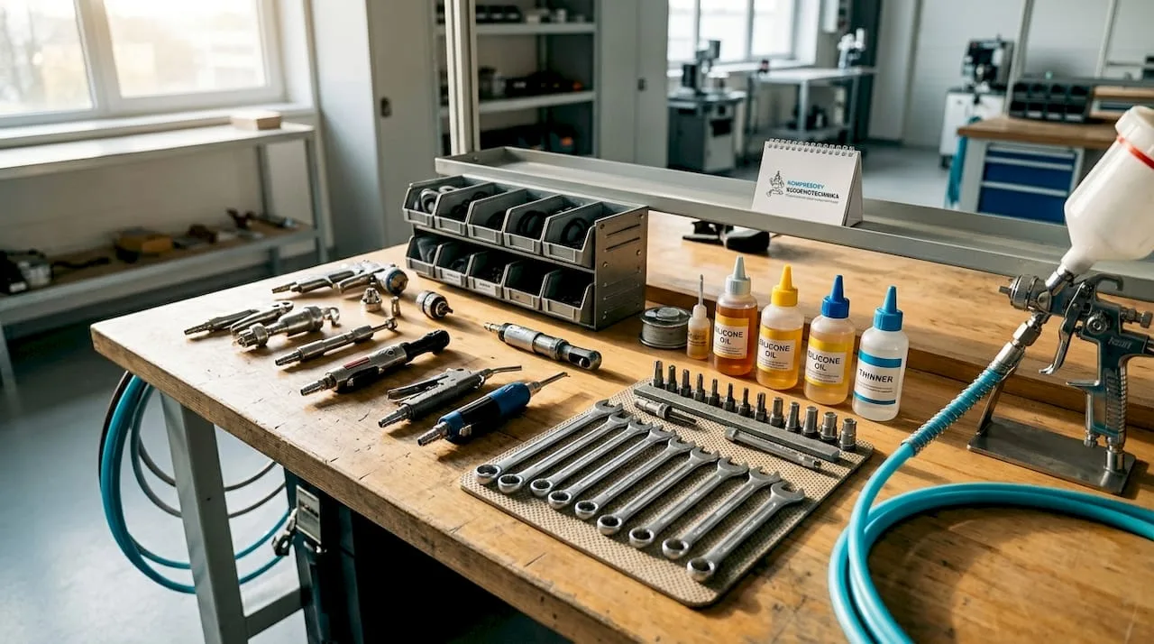
Proper preparation of equipment before cleaning saves time and protects the gun's components from damage. Without the right tools, there is a risk that cleaning will cause more harm than good.
Basic cleaning tools
- Soft brushes of various sizes for cleaning the nozzle, air cap, and internal channels
- Plastic or wooden toothpicks for loosening deposits from small openings
- Clean cloths or paper towels for wiping the outer body of the gun
- Containers or bowls for soaking parts in thinner
- Air gun or blow gun for blowing out residual thinner and moisture
Choosing the right thinner
The choice of thinner depends on the type of paint you used. For water-based paints, warm water with a cleaning agent added is sufficient. For oil-based paints, mineral thinner or white spirit must be used. Thinners for oil-based materials should have a flash point of at least 38 °C for safe operation. Aggressive solvents such as acetone or chlorinated thinners damage rubber seals and shorten the service life of the gun.
Safety equipment
When working with thinners, always use nitrile gloves and safety glasses. Perform cleaning in a well-ventilated area or outdoors, as thinner fumes are harmful to health. Store flammable thinners in their original closed containers, away from heat sources.
Professional tip: Don't pour out the cleaning thinner after first use. Impurities will settle at the bottom of the container and the upper layer of liquid can be reused for pre-cleaning.
How to clean a paint spray gun: exact step-by-step procedure
Cleaning a paint spray gun consists of several consecutive steps. Skipping any of them increases the risk of malfunction or reduced performance.
Preparation before disassembly
- Disconnect the gun from the air source. Never clean the gun with the hose connected under pressure. Remaining pressure in the system can cause uncontrolled spraying of paint or thinner.
- Empty the paint bowl. Pour excess paint back into its original container. Flush the remaining paint in the bowl with a small amount of thinner and dispose of this solution according to local regulations.
- Flush the gun with thinner. Pour a small amount of clean thinner into the bowl and let it flow through the gun by pulling the trigger. Repeat until clean thinner comes out of the gun.
Disassembling the gun
- Remove the air cap. The air cap is usually unscrewed by hand or with the help of a wrench. Place it in a container of thinner to soak.
- Unscrew the nozzle. The nozzle is a sensitive component. When removing it, hold it firmly but carefully so it doesn't fall or become deformed.
- Pull out the needle. Pull the needle out slowly with a straight backward motion. Inspect it visually for bending or damage.
- Disassemble other accessible parts according to the manufacturer's instructions. Not all guns allow full disassembly. Proceed only as far as the manufacturer recommends.
Professional tip: Before disassembly, take photos of the gun from multiple angles. This way you'll know exactly where each part belongs when reassembling.
Cleaning the individual parts
Let the soaked parts (air cap, nozzle) sit in thinner for 10–15 minutes. Then clean them with a soft brush. Never use metal objects to clean the nozzle. Scratching the nozzle surface causes permanent deterioration of the spray pattern that cannot be repaired.
- Clean the air cap holes with a thin soft brush or a plastic toothpick
- Wipe the needle with a cloth soaked in thinner, moving from the base to the tip
- Flush the internal channels of the gun body with thinner using a small brush or a syringe
- Wipe the outer body of the gun with a cloth soaked in thinner
Ultrasonic cleaners are suitable for removing stubborn deposits from internal channels. This method removes dirt from inaccessible areas without abrasive damage and is becoming increasingly popular among professional painters.
Drying and reassembly
- Dry all parts thoroughly. Use compressed air or a clean cloth. Residual moisture combined with the metal parts of the gun creates a corrosion risk in the gun's channels.
- Check the condition of the seals. Replace any cracked or hardened seals before reassembly. A damaged seal causes air and paint leaks.
- Reassemble the gun in reverse order. Follow the manufacturer's instructions exactly. Do not overtighten the parts.
- Check functionality. After reassembly, connect the gun to the air supply and check for leaks. Perform a test spray on paper.
After each use, also clean the air filter to ensure proper air flow and prevent malfunctions.
What are the most common mistakes when cleaning a paint spray gun?
Mistakes in gun maintenance have a direct impact on spray quality and tool lifespan. Most problems arise from carelessness or lack of knowledge of the correct procedure.
Unsuitable thinners and their consequences
Using aggressive or incompatible thinners damages the rubber seals inside the gun. A damaged seal causes air leaks, uneven pressure, and uncontrolled paint dripping. Always use the thinner recommended by the paint or gun manufacturer.
Metal objects in the nozzle
Using sharp metal objects to clean the nozzle leads to irreversible damage to the nozzle surface, resulting in poor paint dispersion. A scratched nozzle produces an uneven or frayed paint spray pattern that cannot be corrected by calibration. The only correct choice is soft brushes or plastic toothpicks.
Insufficient drying before storage
A gun assembled with wet parts corrodes from the inside. Corrosion in the gun's channels contaminates paint during subsequent use and causes surface defects. Every part must be completely dry before assembly and storage.
Manufacturers warn that improper maintenance may lead to the rejection of warranty repairs. Maintenance of the gun is not optional, but a technical requirement for maintaining the warranty and reliability of the tool.
Overview of the most common mistakes
- Using acetone or chlorinated thinners on guns with rubber seals
- Cleaning the nozzle with metal objects (screwdrivers, wires, needles)
- Assembling the gun without thoroughly drying all parts
- Skipping cleaning of the air filter after each use
- Storing the gun without the nozzle mounted
How to properly store the gun after maintenance?
Proper storage extends the service life of the gun and protects sensitive components between individual uses. Improper storage can ruin even a perfectly cleaned gun.
Protection of the needle and nozzle
Manufacturers recommend never storing the gun without the nozzle attached. The nozzle protects the needle from bending and mechanical damage. A bent needle causes an asymmetric spray pattern and cannot be straightened without the risk of breaking.
Lubrication of the moving parts
Lightly lubricate the moving parts of the gun, especially the needle and trigger mechanism, with silicone oil or special oil for pneumatic tools. Regular lubrication of moving parts preserves the functionality of the components and prevents them from seizing. Lightly coat the outer body of the gun with silicone oil to protect against corrosion.
Professional tip: For long-term storage, disassemble the gun, clean it and lubricate the moving parts. Store the parts in a clean bag or box to prevent dust from settling on them.
Storage conditions
- Dry environment with low air humidity
- Temperature without extreme fluctuations (do not expose to frost or direct sunlight)
- Protection against dust using a closed case or bag
- Store out of reach of aggressive chemicals and solvents
Never store the gun with paint in the bowl. Paint dries, clogs the channels and causes problems that require costly repair or replacement of parts.
Key takeaways
Regular and properly performed maintenance of the paint spray gun is the only way to ensure quality spraying and a long service life of the tool.
| Item | Details |
|---|---|
| Cleaning after each use | Flush the gun with thinner immediately after finishing work, before the paint has dried. |
| Correct thinners | Always use a thinner compatible with the type of paint and with a flash point of min. 38 °C for oil-based materials. |
| Nozzle protection | Never clean the nozzle with metal objects, scratches are permanent and cannot be repaired. |
| Drying before storage | All parts must be completely dry, otherwise corrosion occurs in the gun's channels. |
| Storage with the nozzle | The nozzle protects the needle from bending, never store the gun without it. |
What I have learned after years of working with spray guns
Most users underestimate nozzle cleaning during normal operation. Yet it is precisely a clogged nozzle that is the most common cause of spraying problems, which people mistakenly attribute to bad paint or the compressor. I experienced this myself: the gun worked "almost fine", the spray pattern was a bit grainy, and I kept changing the paint, pressure, and distance. The problem was the nozzle, which wasn't clean even after an apparent flush.
The second thing that surprised me is how few users lubricate the needle. The needle moves with every trigger pull, and without lubrication it gradually seizes up. The result is a stiff trigger and inaccurate paint metering. A few drops of silicone oil after each cleaning completely eliminates this problem.
I also recommend trying HVLP or LVLP spray guns if you're still working with an older type. These guns are designed with easier cleaning in mind and have fewer hidden channels where paint can build up. Maintenance then takes less time and the results are more consistent.
Last piece of advice: keep a simple maintenance logbook. Write down the cleaning date, the type of paint used, and the condition of the seals. The next time you have a spraying problem, you'll immediately know when you last cleaned the gun and what you replaced. This small detail saves hours of troubleshooting.
— Zdeněk
Equipment and accessories for spray gun maintenance
Kompresory-vzduchotechnika offers a range of pneumatic accessories and spare parts suitable for the regular maintenance of spray guns.
On the Kompresory-vzduchotechnika website, you'll find pneumatic components and accessories for servicing and maintaining guns, including lubricating oils, replacement filters, and seals. The technical support team can advise on selecting the right accessories for a specific type of gun. If you're looking for a new gun or spare parts, the gun selection guide will help you decide based on the type of work and material. Kompresory-vzduchotechnika provides technical advice for professionals and hobby users alike.
Frequently asked questions
How often should a spray gun be maintained?
Clean the gun after every use, while the paint is still fresh. For long-term storage, perform a complete disassembly, cleaning, and lubrication of all moving parts.
What thinner should be used to clean the gun?
Use a thinner compatible with the type of paint you sprayed. For oil-based paints, choose thinners with a flash point of at least 38 °C; for water-based paints, warm water is sufficient.
Can the nozzle be cleaned with a metal needle or a screwdriver?
No. Metal objects will permanently scratch the nozzle and worsen paint atomization. Use only soft brushes or plastic toothpicks.
Why should the gun be stored with the nozzle mounted?
The nozzle protects the needle from bending and mechanical damage during storage. A bent needle causes asymmetric spraying, and replacing it is costly.
Can improper maintenance void the gun's warranty?
Yes. Manufacturers explicitly state that improper maintenance may be grounds for rejecting a warranty repair. Regular and properly performed maintenance is a condition for claiming the warranty.
Recommended
- How pneumatics works: a complete guide for industry 2026
- How to Safely Use Pneumatic Tools: A Guide - Kompresory-Vzduchotechnika.cz
- What is pneumatic lubrication: a guide for technicians - Kompresory-Vzduchotechnika.cz
- List of Professional Spray Guns 2026: A Guide for Technicians - Kompresory-Vzduchotechnika.cz

How Air Quality Affects Performance in Industry
In brief:
- Air quality affects employee performance as well as the reliability of technical equipment. Harmful substances and particles reduce cognitive abilities, increase sickness rates and equipment failure rates. Proper filtration and air quality monitoring bring measurable improvements in efficiency and reduce costs.
Air quality is defined as the level of presence of harmful substances, humidity and particles in the working environment, and it directly determines employee performance as well as the reliability of technical equipment. WHO standards set the recommended limit for PM2.5 at 5 µg/m³ as an annual average, while the RESET and WELL standards define strict limits for volatile organic compounds (VOC) indoors. In industry, construction and automotive, however, these values are regularly exceeded. The result is a measurable decline in productivity, higher equipment failure rates and increased worker absenteeism. How air quality affects performance is not a matter of theory. It is an operational reality with direct economic impacts.
How does air quality affect employee performance?
Polluted air provably and measurably reduces workers' cognitive abilities. At high VOC concentrations, cognitive abilities decrease by up to 61%, while with optimized ventilation, performance scores increase by 101%. Every increase in TVOC of 500 µg/m³ correlates with a 13% decline in scores for decision-making, reaction and concentration. These are figures that translate directly into error rates on the production line or into the quality of decisions made by a site manager.
Physical performance and breathing are affected particularly by fine PM2.5 dust particles. These particles penetrate deep into the lungs and cause inflammation of the respiratory tract. A 2024 Italian study confirmed that regions with higher levels of air pollution show up to 30% higher hospitalization rates due to respiratory diseases. For industrial operations, this means higher absenteeism and lower physical endurance of workers during demanding operations.
The impact of air pollution is also manifested at the mental level. High concentrations of VOC lead to fatigue, headaches, reduced concentration and faster mistakes at work. Sick building syndrome (SBS) affects workers in spaces with insufficient ventilation and high concentrations of emissions from paints, adhesives or cleaning agents. These symptoms are not subjective complaints. They are a measurable result of poor air quality.
Air quality in the workplace directly affects strategic thinking. Under worse conditions, cognitive abilities decrease similarly to after alcohol consumption. For technicians and managers in industry, this means that air in the hall is not just a matter of hygiene, but a factor of safety and production quality.
The global context is alarming. Only 13 out of 143 monitored countries met average PM2.5 concentrations below the recommended WHO threshold. The Czech Republic is at an average level, but industrial halls and construction sites generally have significantly worse values than outdoor air. The fact that reducing concentrations of pollutants leads to reduced absenteeism and increased productivity also shows why clean air is important for performance.
Key impacts of VOC and PM2.5 on workers:
- Decision-making and reaction: a 13% drop in score for every increase in TVOC of 500 µg/m³
- Physical endurance: PM2.5 causes inflammation of the respiratory tract and reduces aerobic capacity
- Absenteeism: higher concentrations of pollutants correlate with higher sickness rates and staff turnover
- Safety: reduced concentration increases the risk of workplace accidents
- Morale: chronic health problems reduce worker motivation and loyalty
How does poor air quality damage technical equipment and HVAC systems?
Airborne contaminants damage technical equipment both physically and chemically. A 1 mm layer of dust on a heat exchanger reduces its efficiency by up to 15%. This means that a compressor or FCU unit must operate with higher power input to achieve the same output. The result is higher operating costs and a shorter equipment lifespan.

Deposits cause vibration and premature wear of motors and fans. Uneven buildup on fan blades disrupts rotor balance. This phenomenon manifests as increased noise, higher thermal stress on bearings, and eventually failure. In automotive painting or industrial assembly, such a failure can stop the entire production line.
Air humidity represents a separate category of risks. High humidity creates an environment for mould growth in FCU units, leading to air contamination and health risks. Dry air, on the other hand, increases fan wear and reduces compressor efficiency. The optimal humidity for industrial conditions lies in the range of 40–50%, where both risks are minimised.
VOCs cause chemical degradation of seals and insulation materials. Aggressive organic compounds from industrial processes attack rubber seals in compressors and valves. The result is refrigerant leaks, pressure drops in pneumatic circuits, and the need for premature component replacement. Regular industrial air filtration slows down these processes and extends service intervals.
Professional tip: Filters rated MERV 13 and higher capture particles as small as 0.3 µm and prevent dust from settling on heat exchangers. Regular cleaning and replacement of these filters extends equipment lifespan and reduces energy costs by maintaining heat exchanger efficiency.
| Type of contamination | Impact on equipment | Recommended measure |
|---|---|---|
| Dust particles (PM2.5, PM10) | Reduction in heat exchanger efficiency by up to 15%, rotor vibrations | MERV 13+ filters, HEPA, regular cleaning |
| Volatile organic compounds (VOC) | Seal degradation, refrigerant leaks, corrosion | Activated carbon filters, controlled ventilation |
| High humidity (above 60%) | Mould growth in FCUs, contact corrosion | Dehumidifiers, humidity monitoring |
| Low humidity (below 30%) | Electrostatic discharges, fan wear | Humidifiers, regulation to 40–50% |
How to measure and monitor air quality in industrial facilities?
Measuring air quality in industry requires a combination of sensors for different types of pollutants. TVOC sensors detect the total concentration of volatile organic compounds in real time. PM2.5 sensors measure the mass concentration of fine particles. Both types of sensors are now available as compact industrial modules with output to control systems.
Data-driven automated ventilation systems are the most effective tool for maintaining air quality. TVOC sensors enable real-time triggering of controlled ventilation that keeps pollutant concentrations below recommended limits. This approach, known as demand-controlled ventilation, activates ventilation only when actually needed. The result is lower energy consumption while maintaining air quality.
Certification standards WELL, LEED, and RESET define specific limits for indoor air parameters and provide a framework for their verification. The RESET standard, for example, requires continuous monitoring with certified sensors and regular data reporting. For industrial facilities supplying the automotive or pharmaceutical sector, meeting these standards may be a condition for winning a contract.
Procedure for implementing air quality monitoring in a facility:
- Mapping pollution sources: identify processes producing VOCs, dust, or moisture (welding, painting, grinding, chemical cleaning)
- Sensor selection: deploy a combination of TVOC, PM2.5, and humidity sensors at key locations throughout the facility
- Integration into the control system: connect sensors to the ventilation system for automatic ventilation activation
- Alarm configuration: define threshold values for immediate operator response when limits are exceeded
- Regular calibration: calibrate sensors at least once a year according to the manufacturer's recommendations
- Reporting and analysis: monitor trends and identify recurring problems for preventive measures
| Parameter | Recommended limit (WHO/WELL) | Measurement method |
|---|---|---|
| PM2.5 | 5 µg/m³ (annual average) | Optical sensors, gravimetry |
| TVOC | below 300 µg/m³ | Photoionization detector (PID) |
| CO2 | below 1,000 ppm | Infrared sensors (NDIR) |
| Relative humidity | 40–50 % | Capacitive sensors |
| Temperature | 18–24 °C | Thermistors, PT100 |
Practical steps to improve performance with air in operations
Improving air quality in an industrial facility starts with proper filtration. F7 to F9 class filters capture medium and coarse particles and protect heat exchangers from fouling. For environments with high dust levels or chemical emissions, HEPA filters or active carbon filters are essential. Selecting the correct filtration class depends on the specific production process and air quality parameters.
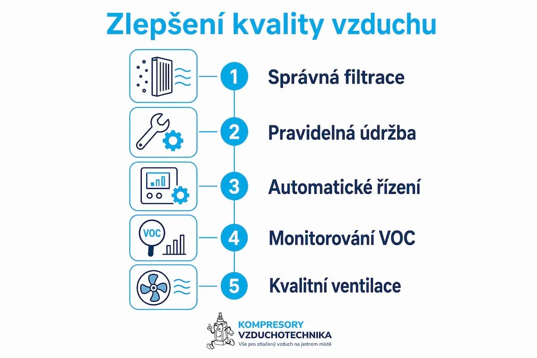
Regular maintenance of ventilation systems is a condition for maintaining performance. A clogged filter increases pressure drop in the system and forces the fan to operate with higher power input. Replacing filters based on actual condition, not just according to a time schedule, saves energy and prevents failures. Cleaning heat exchangers and fan blades should be part of the regular service plan.
Reducing VOC emissions in operations requires selecting suitable materials and processes. Low-VOC coatings, water-based adhesives, and enclosed systems for chemical processes reduce pollutant concentrations at the source. These measures are more effective than additional filtration, as they eliminate the problem before it arises.
Key measures for improving performance with air:
- Heat recovery: recovering heat from exhaust air reduces heating costs while maintaining intensive ventilation
- Compressed air filtration: for pneumatic tools and painting, compressed air purity according to ISO 8573 is a condition for output quality
- Humidity management: maintaining humidity in the range of 40–50% protects both equipment and workers
- Zonal ventilation: separate ventilation for different production zones prevents the spread of contamination
- Operator training: workers must know the symptoms of air quality deterioration and the reporting procedure
Professional tip: When renovating ventilation systems in an automotive paint shop or an industrial hall, always first carry out an air quality audit with TVOC and PM2.5 measurement. Without input data, it is not possible to correctly size the filtration and ventilation system or to demonstrate improvement after installation.
Investment in air quality management systems pays off through lower equipment failure rates, higher productivity, and lower worker absenteeism. Indoor air quality is just as important as drinking water quality. Proper ventilation and filtration are not a luxury but a technical foundation for a healthy and productive working environment.
Key findings
Air quality directly determines both employee performance and the reliability of technical equipment, with improvements in filtration and ventilation bringing a measurable increase in productivity and a reduction in operating costs.
| Point | Details |
|---|---|
| VOCs and cognitive performance | An increase in TVOC of 500 µg/m³ reduces decision-making and concentration scores by 13%. |
| Dust and equipment efficiency | A 1 mm layer of dust on a heat exchanger reduces its efficiency by up to 15%. |
| Optimal humidity | Maintaining humidity at 40–50% protects equipment from mold and wear. |
| Real-time monitoring | TVOC and PM2.5 sensors enable automatic ventilation control without manual intervention. |
| MERV 13+ and HEPA filtration | Regular filter replacement extends equipment lifespan and reduces energy costs. |
Air in industry: what I've learned over years in operation
I've worked in halls where nobody addressed air quality until compressors started failing or technicians began reporting headaches. Only then was the cause sought retroactively, at the cost of downtime and expensive repairs. This reactive approach is still too common in industry.
What surprised me most was discovering how quickly the situation improves after installing proper filtration and sensors. Technicians work with better focus, equipment runs quieter, and service intervals extend. This isn't a placebo effect. It's physical reality: fewer contaminants in the system means less friction, less heat, and fewer failures.
Conventional wisdom says filtration is a cost. I consider it an investment with one of the shortest payback periods in industrial operation. If you know that a clogged heat exchanger increases energy consumption by 15%, then replacing a filter for CZK 500 to prevent that is a trivial decision.
I recommend every operations technician start with a simple audit: measure TVOC and PM2.5 at three locations in the hall, compare with WHO and WELL limits, and check when you last changed the filters. The results will likely surprise you. And if not, you have data confirming that your operation is running correctly.
— Zdeněk
Clean air solutions from Kompresory-vzduchotechnika
Kompresory-vzduchotechnika offers technical solutions for air filtration and treatment in industrial, construction and automotive operations. The product range includes filtration units for compressed air, accessories for piping systems and components for air quality control according to ISO 8573.
For operations where air quality directly affects equipment performance and worker productivity, Kompresory-vzduchotechnika offers air treatment units to ensure the cleanliness and stability of compressed air. The complete range of pneumatics and air technology, including expert consultation, is available at pneumatics & hydraulics. The Kompresory-vzduchotechnika technical team provides consultations on selecting the right solution for specific operating conditions.
Frequently Asked Questions
How does air quality affect employee performance?
Polluted air with a high concentration of VOCs reduces cognitive abilities by up to 61% and causes fatigue, headaches and a higher error rate. Optimized ventilation, on the other hand, increases performance scores by 101%.
What is the impact of PM2.5 on industrial equipment?
Fine dust particles settle on heat exchangers and reduce their efficiency by up to 15%. This increases the power consumption of compressors and fans and shortens their service life.
What is the optimal air humidity for industrial operation?
The optimal relative humidity for industrial conditions is 40–50%. Higher humidity promotes mold growth in HVAC systems, while lower humidity increases fan wear and the risk of electrostatic discharge.
How do smog and outdoor air pollution affect performance in halls?
Polluted outdoor air enters halls through the ventilation system and increases indoor concentrations of PM2.5 and VOCs. Without quality intake filtration, the effects of outdoor air pollution are transferred directly to workers and equipment inside.
What filters are suitable for industrial air filtration?
Industrial facilities are recommended to use MERV 13 and higher class filters, or HEPA filters for environments with high dust levels or chemical emissions. Compressed air filtration is governed by the ISO 8573 standard, which defines purity classes for various applications.
Recommended
- Air treatment: maximum efficiency for industry and construction - Kompresory-Vzduchotechnika.cz
- Definition of quality air: parameters, standards and measurement - Kompresory-Vzduchotechnika.cz
- The importance of compressed air automation in industry - Kompresory-Vzduchotechnika.cz
- Why air purity is measured: methods and health - Kompresory-Vzduchotechnika.cz

What is pneumatic logic: a guide for industry

Summary:
- Pneumatic logic uses compressed air to control functions without electrical energy. It is used in industrial automation, where it emphasizes reliability and simplicity. Proper design and documentation according to standards increase its efficiency and the service life of systems.
Pneumatic logic is a control system that uses compressed air to implement logical functions such as AND, OR, and NOT, without the need for electrical energy. This approach is used in industrial automation, on production lines, and in construction, where system reliability and simplicity take precedence over complex electronics. Standards such as ISO 1219-2 and ANSI/JIC define standardized methods for designing and documenting these systems. Pneumatic logic combines thermodynamics, fluid mechanics, and control theory into a single functional unit capable of controlling cylinder movements, motion sequences, and safety interlock functions.
What is pneumatic logic and how does it work?
Pneumatic logic is defined as the use of compressed air to transmit and process control signals in technical systems. Unlike electrical logic, which operates with voltage and current, pneumatic logic operates with pressure impulses passing through valves and piping. The result is a system resistant to electromagnetic interference, explosive environments, and high humidity.
Pneumatic theory states that pneumatics is not just air in pipes, but controlled energy transfer using thermodynamics, fluid mechanics, and control theory. This combination of disciplines makes it possible to design systems that respond precisely and repeatably even under demanding operating conditions.
Basic components of a pneumatic logic system
Every pneumatic logic system consists of several key elements:
- Pneumatic logic valves implement the AND, OR, and NOT logical functions using pressure signals. Input pressure opens or closes the air flow at the output.
- Pressure regulators maintain the operating pressure within the required range. Integrated logic regulators typically operate in the range of 2–8 bar and at temperatures from -15 °C to +60 °C.
- Pneumatic timers provide a time delay between individual steps of a sequence. Their accuracy and repeatability must be verified before being put into operation.
- Pneumatic counters track the number of cycles or pulses and enable conditional process control.
- Interlocking elements prevent the simultaneous activation of conflicting signals and protect valves and actuators from damage.
Professional tip: When designing a system, always verify that the operating pressure matches the specifications of each logic element individually. A pressure deviation outside the permitted range causes unreliable valve switching.
The AND logic function in pneumatics requires a pressure signal to be present at both inputs simultaneously in order to open the output. The OR function allows air through if at least one of the inputs is active. The NOT function inverts the input signal. These three basic functions form the building blocks of more complex control sequences.
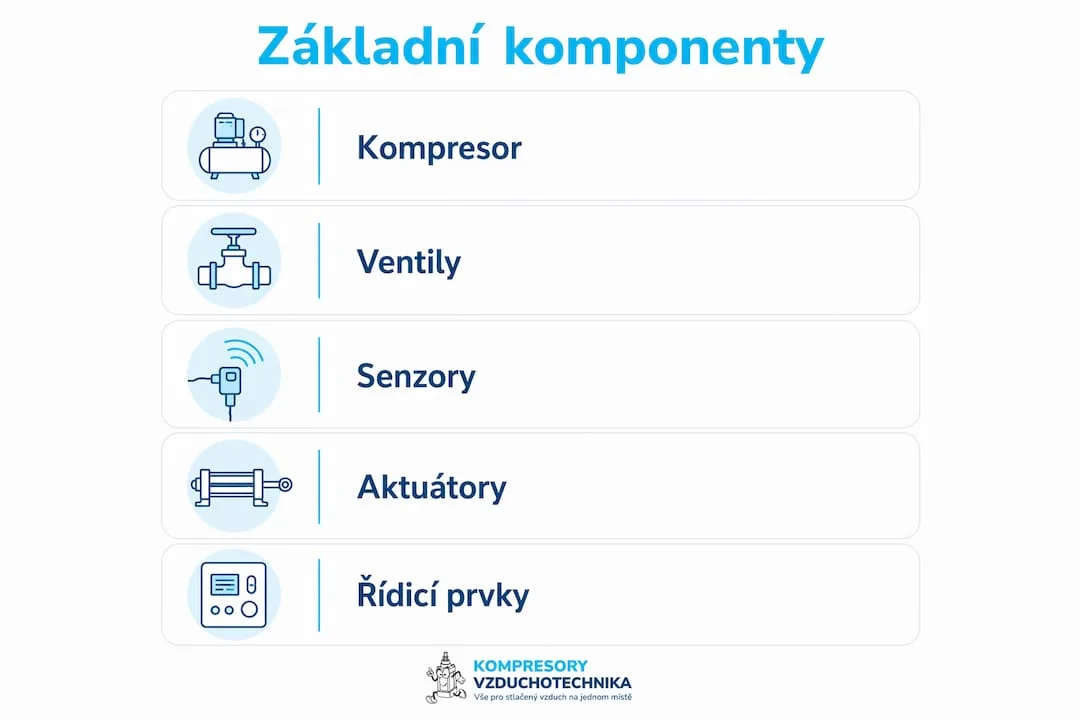
What standards apply to the design of pneumatic systems?
The design and documentation of pneumatic logic systems is governed by several internationally recognized standards. Compliance with them is not just a formal requirement. Standards directly affect reliability, the clarity of documentation, and the speed of fault diagnosis.
Sequence diagrams according to ISO 1219-2 visualize the time relationships between individual steps of a sequence and enable precise design as well as efficient maintenance. Underestimating documentation significantly complicates repairs and extends production downtime.
| Standard | Area of application |
|---|---|
| ISO 1219-2 | Graphic symbols and sequence diagrams for pneumatic circuits |
| ANSI/JIC | American standard for hydraulic and pneumatic system diagrams |
| IEC 60848 | GRAFCET language for describing sequential control systems |
| VDI 3260 | German standard for pneumatic circuits and their documentation |
Each of these standards approaches documentation from a different angle. ISO 1219-2 focuses on graphic symbols and sequential diagrams. IEC 60848 defines the GRAFCET language, which describes sequences of steps and transitions in the form of a state diagram. VDI 3260 is widespread mainly in German-speaking countries and in Central European industry.
Professional tip: When designing a new system, start with a sequential diagram according to ISO 1219-2 before selecting components. The diagram will reveal potential signal conflicts before they generate the cost of physical prototypes.
Accurate recording of valve time constants in the documentation is essential for system stability. The time constant of a valve determines how quickly the valve responds to a control signal. If this value is missing from the documentation, the technician has no basis for comparison in the event of a fault, and diagnostics take significantly longer.
Where is pneumatic logic used in industry and construction?
Pneumatic logic finds application wherever it is necessary to control movements, sequences, or conditional functions without dependence on electrical infrastructure. Industry and construction offer dozens of specific applications.
The most common uses include:
- Control of pneumatic cylinders in assembly lines, where the sequence of movements must take place in an exact order. Pneumatic logic ensures that cylinder B moves only after cylinder A has completed its movement.
- Handling systems for moving parts between workstations. Pneumatic logic circuits coordinate grippers, rotary tables, and conveyor belts.
- Production lines in the food and pharmaceutical industry, where electrical equipment poses a risk of contamination or explosion. Purely pneumatic control eliminates this risk.
- Construction machinery and lifting equipment, where pneumatic logic controls safety sequences and interlock functions.
- Test stations for verifying the tightness or strength of products using pressure tests.
Automation in pneumatics in production processes shows that a properly designed pneumatic logic system reduces dependence on operators and increases production repeatability. Modern intelligent pneumatic control combined with IoT and edge computing can reduce energy costs by 25–35%. This saving results from precise control of air consumption and the elimination of unnecessary leaks or overpressurization.
Pneumatic logic is also used in sorting and packaging systems. Logic circuits here decide on product routing based on pressure signals from sensors. The result is fast and reliable sorting without complex electronics.
How does proper design increase the reliability of a pneumatic system?
The reliability of a pneumatic logic system depends directly on the quality of its design. Design errors manifest as random failures, incorrect sequences, or component damage.
The recommended design procedure includes the following steps:
- Creating a sequence diagram before selecting any components. The diagram reveals signal conflicts and allows the sequence logic to be verified on paper.
- Selecting components according to operating conditions. Pressure, temperature, cycle frequency, and medium type must match the specifications of each component. Proper component selection can eliminate up to 90% of control failures. This figure shows that most failures do not result from wear but from faulty design.
- Validation of timers and interlock elements. Pneumatic timers must demonstrate accuracy and repeatability at different temperatures and pressures. Testing takes place before commissioning, not after the first failure.
- Implementation of interlock protection. Interlock protection prevents the simultaneous transmission of conflicting signals. Without it, there is a risk of mechanical damage to cylinders or valves when conflicting commands are activated at the same time.
- Preventive maintenance setup. Regular filter inspection, automatic lubricators and seals extends system service life. Monitoring operating pressure and flow detects leaks before they cause a failure.
Safety features form an integral part of every reliable system. Pneumatic safety in industry includes not only anti-blocking protection but also safety valves, position sensors and emergency relief circuits. These elements protect both the equipment and the operator.
Modern pneumatic automation increasingly integrates IoT communication protocols and edge computing for predictive maintenance. Sensors monitor pressure, flow and temperature in real time. The system alerts to a deviation from normal condition before a failure occurs.
Key findings
Pneumatic logic is a reliable foundation of industrial automation, whose performance depends on proper design, standardized documentation and regular component validation.
| Point | Details |
|---|---|
| Definition of pneumatic logic | A control system using compressed air to implement AND, OR and NOT logic functions. |
| Operating parameters | Logic controllers operate in the range of 2–8 bar and temperatures from -15 °C to +60 °C. |
| Impact of design on reliability | Correct component selection eliminates up to 90% of pneumatic control system failures. |
| Key standards | ISO 1219-2, ANSI/JIC, IEC 60848 and VDI 3260 define standards for design and documentation. |
| Energy savings | Intelligent pneumatic control reduces energy costs by 25–35% compared to conventional systems. |
Pneumatic logic in practice: what technicians overlook
I have worked with pneumatic systems for many years, and I repeatedly encounter the same problem. Technicians pay great attention to selecting valves and cylinders, but devote minimal time to documentation and sequence diagrams. The result becomes apparent at the first major failure. Nobody knows what time constants were set during commissioning, and diagnostics take days instead of hours.
The second thing that surprises me is the underestimation of anti-lockup protection. I have seen systems where this function was completely missing. When conflicting signals were activated simultaneously, both the valves and the mechanical parts of the cylinder were damaged. The repair cost many times more than a correct design from the start.
Trends in automation are clearly moving toward integrating pneumatics with IoT sensors and predictive maintenance. This combination makes sense, but the basic prerequisite is having a correctly designed and documented pneumatic circuit. Without a solid foundation, no smart add-on will help.
I recommend one rule to technicians and designers: a sequence diagram according to ISO 1219-2 is a mandatory output of every project, not an optional addition. Systems with quality documentation are repaired faster, more cheaply, and with less risk of error during repair.
— Zdeněk
Pneumatic components and expert support in one place
Kompresory-vzduchotechnika offers a range of pneumatic components for industrial and construction applications, from pressure regulators and logic valves to accessories for compressed air distribution.
The technical support team at Kompresory-vzduchotechnika helps with selecting the right components for a specific application. Whether designing a new system or replacing existing components, expert advice shortens the time from selection to a functional solution. The entire range of pneumatics and hydraulics is available online with the option of consultation. For compressed air distribution, push-in system pipes are also available in diameters of 15–28 mm.
Frequently Asked Questions
What is pneumatic logic and what is it used for?
Pneumatic logic is a control system that uses compressed air to implement AND, OR, and NOT logic functions without electrical energy. It is used to automate movement sequences, control cylinders, and provide safety interlock functions in industry and construction.
What pressure do pneumatic logic elements require?
Integrated pneumatic logic regulators operate within a range of 2–8 bar and temperatures from -15 °C to +60 °C. Exact values depend on the specific type of component and manufacturer.
What is the difference between pneumatic and electrical logic?
Pneumatic logic works with pressure signals and does not require electrical energy, making it suitable for explosive or damp environments. Electrical logic offers faster switching speeds and easier integration with digital control systems.
Why is documentation of pneumatic systems so important?
Sequence diagrams according to ISO 1219-2 visualize the time relationships and logic of sequences. Without proper documentation, fault diagnosis takes significantly longer, and the risk of error during repair increases.
How does pneumatic logic save energy?
Smart control of pneumatic systems combined with IoT sensors reduces energy costs by 25–35% through precise control of air consumption and the elimination of leaks. Pneumatic logic itself saves energy by not requiring power for control elements.
Recommended
- What is pneumatic automation: a guide for industry - Kompresory-Vzduchotechnika.cz
- How pneumatics works: a complete guide for industry 2026
- What is pneumatic lubrication: a guide for technicians - Kompresory-Vzduchotechnika.cz
- The Role of Automation in Pneumatics in Manufacturing Processes - Kompresory-Vzduchotechnika.cz

Benefits of a centralized air distribution system in industry
We have merged this article with a more detailed and more up-to-date guide on the same topic. Continue here: A guide to industrial air distribution: efficiency of operation.

Compressed air storage options: a guide for technicians
In short:
- A properly designed compressed air storage system reduces compressor cycling and extends its service life. A wet air tank is installed before the dryer, a dry air tank after it, which affects the air quality in the system. UCAES is long-term underground energy storage with an efficiency of around 70 percent, suitable for large energy projects.
Compressed air storage is defined as a controlled, maintained reserve of compressed air in a pressure vessel or underground reservoir that balances the difference between compressor output and instantaneous demand. A properly designed storage system reduces the number of compressor starts, stabilizes operating pressure, and extends the service life of the entire equipment. Compressed air storage options range from simple air tanks through multi-purpose pressure vessels to industrial CAES (Compressed Air Energy Storage) systems. Choosing the right solution directly affects the energy efficiency of operation and operating costs.
1. What are the basic types of pressure vessels for storing compressed air?
The pressure vessel, in practice referred to as an air tank or air reservoir, forms the basis of every compressed air storage system. Air tanks are divided according to their position in the system into wet and dry, and this division fundamentally affects both air quality and dryer function.
Wet air tank
A wet air tank is installed before the air dryer, i.e. directly after the compressor. The air inside it contains moisture and condensate, which settle here and separate from the air stream. The wet air tank thus functions as a primary condensate separator and also reduces the air temperature before it enters the dryer. The choice of wet air tank fundamentally affects the dryer's operation and the quality of compressed air throughout the system.
Dry air tank
A dry air tank is placed after the air dryer. The air entering it has already been dried, so the tank serves purely a balancing function. It stabilizes the pressure in the distribution network and dampens pressure surges caused by sudden draw-offs. For applications requiring high air quality, such as in mechanical engineering or the food industry, a dry air tank is an essential part of the system.
Key parameters when selecting an air tank:
- Tank volume must correspond to the compressor output and peak consumption; an undersized air tank causes frequent cycling and motor overheating.
- Maximum working pressure must be compatible with the compressor's pressure. A higher pressure in the tank does not mean a greater flow rate, but rather a reduction in it.
- Material and surface treatment affect resistance to corrosion, especially with wet air receivers.
- Safety equipment includes a safety valve, pressure gauge, and condensate drain valve.
Professional tip: Automatic condensate drainage is more reliable than manual draining. With wet air receivers, condensate accumulates quickly, and regular draining prevents corrosion and damage to the tank.
2. Modern CAES systems and their industrial applications
CAES (Compressed Air Energy Storage) is a technology for long-term energy storage in the form of compressed air in underground reservoirs, such as salt caverns, depleted mines, or porous rock formations. The system works by using surplus electrical energy to drive compressors that compress and store the air. When needed, the air is released, heated, and drives a turbine or expansion machine that generates electricity.
CAES systems achieve an overall efficiency of around 70% and a lifespan exceeding 30 years. This performance is comparable to pumped-storage hydroelectric plants, which are currently the most widespread technology for grid-scale energy storage.
The three basic CAES concepts differ in how they handle the heat generated during compression:
- Diabatic CAES releases the heat generated during compression into the environment and, during expansion, heats the air using natural gas. It is the oldest and simplest concept, but it loses part of the energy.
- Adiabatic CAES captures the heat and stores it in a thermal energy storage (TES) system. During expansion, it returns the heat back into the air, eliminating the need for fossil fuels. Advanced CAES systems with TES achieve higher overall energy efficiency.
- Isothermal CAES keeps the air temperature constant throughout both compression and expansion. It is theoretically the most efficient approach, but its practical implementation is technically demanding.
CAES systems function as a balancing reservoir for renewable energy sources. They store surplus electricity from wind and solar power plants in the form of compressed air and release it when production is insufficient to cover demand. This rapid response capability makes them a key element of modern energy grids.
Typical components of an industrial CAES system include multi-stage compressors, coolers, an underground reservoir, a heat management system, and an expansion turbine. The main challenge remains heat loss during compression, which reduces the overall efficiency of the system unless the heat is actively captured and reused.
3. Key factors affecting air receiver sizing
Correct air receiver sizing is the most common mistake in compressed air system design. An undersized air receiver causes frequent compressor cycling, motor overheating, and premature equipment failure. Conversely, an oversized tank unnecessarily increases investment costs and takes up space.
Factors that determine the correct air receiver volume:
- Compressor output indicates the maximum air flow in liters per minute or m³/hour. The air receiver volume should correspond to at least four times this flow rate for standard applications.
- Peak demand is the maximum instantaneous air consumption during operation. Taking peak demand into account when sizing reduces operating costs and increases the efficiency of the entire system.
- Required operating pressure must match the pressure of the compressor and the connected equipment. A mismatch in pressure parameters leads to reduced flow and system instability.
- Length of the pipework affects pressure losses. Longer piping requires a larger storage volume to maintain stable pressure at the end points of consumption.
A correctly sized air receiver extends the service life of compressors by minimizing unwanted cycling and mechanical load. Every unnecessary compressor start shortens the service life of the motor, valves, and seals.
Additional equipment that increases system reliability:
- Air dryers (refrigerant or adsorption type) remove moisture and prevent corrosion in the distribution network.
- Filters capture oil, solid particles, and microorganisms according to the ISO 8573-1 purity class.
- Automatic condensate drains ensure regular draining without the need for operator attention.
Professional tip: When designing a system, always allow for a 20% margin above peak demand. This margin will cover future expansion of operations without the need to replace the air receiver. For more detail on this topic, see the guide to selecting an industrial compressor.
4. Comparison of compressed air storage systems by parameters
Choosing the right system depends on the operating scenario, available space, required air quality, and investment budget. The table below summarizes the key characteristics of each type.
| Parameter | Wet air tank | Dry air tank | CAES system |
|---|---|---|---|
| Position in the system | Before the dryer | After the dryer | Underground reservoir |
| Function | Condensate separator, cooling | Pressure equalization, storage | Long-term energy storage |
| Air quality | Lower (wet air) | High (dry air) | Depends on treatment |
| Typical volume | 50–5,000 l | 50–5,000 l | Thousands of m³ |
| Service life | 15–25 years | 15–25 years | Over 30 years |
| Investment costs | Low to medium | Low to medium | Very high |
| Typical use | Workshop, production | Production, food industry | Energy grid, industry |
| Energy efficiency | Depends on sizing | Depends on sizing | Around 70% |
A wet air receiver is the right choice for most standard industrial operations where an air dryer is part of the system. A dry air receiver is essential where air quality directly affects the product or process, for example in the pharmaceutical industry or in painting. CAES systems are economically justified only for large-capacity applications in the energy sector or heavy industry, where power outputs are in the order of megawatts.
For optimizing compressed air consumption in smaller operations, a properly sized air receiver combined with a dryer and filters is sufficient. In these cases, investment in CAES would not pay off.
5. Installation, maintenance and safety of pressure vessels
Proper installation of the air receiver determines the safety and efficiency of the entire system. The pressure vessel must meet the requirements of Directive PED 2014/68/EU and be marked with the CE mark. Regular inspection in accordance with ČSN 69 0012 is a legal obligation for vessels above the specified pressure and volume limit.
Principles of proper installation and operation:
- Install the air receiver on a flat, solid surface with sufficient access for inspections and maintenance.
- The safety valve must be set to the maximum working pressure of the vessel and must not be blocked.
- Size the inlet and outlet piping so that no pressure losses occur at the joints.
- Drain condensate regularly. For wet air receivers, daily inspection or installation of an automatic drain is recommended.
The use of air dryers and filters significantly increases the quality of the stored air and extends the service life of equipment. Moisture and impurities in the air accelerate internal corrosion of the air receiver and damage pneumatic tools and control elements.
Inspections include a visual check of the outer shell, inspection of the safety valve, ultrasonic wall thickness measurement, and testing of the safety equipment. Neglecting inspections increases the risk of an accident and can have legal consequences for the operator.
6. Energy efficiency and savings with proper storage
Proper compressed air storage directly reduces operating costs. A compressor operating in regular cycles consumes less energy than a machine that starts and stops unnecessarily. Proper air storage ensures regular compressor cycles and reduces unnecessary starting.
Pressure losses in the system are another source of energy waste. Each bar of pressure loss in the distribution network corresponds to approximately 7% higher compressor energy consumption. A properly sized air receiver combined with quality piping and seals minimizes pressure losses.
CAES systems help balance fluctuations in wind and solar energy by storing surplus electricity as compressed air with the possibility of rapid release. For industrial facilities connected to renewable sources, CAES represents a way to reduce dependence on the grid during periods of peak electricity prices.
Real-time monitoring of pressure and flow allows the identification of air leaks and inefficient consumption. Air leaks in industrial facilities account for a significant portion of total compressed air consumption. Regular system audits are therefore part of efficient operation. More on this topic is provided by the overview of air treatment for industry.
Key Takeaways
Correct sizing and selection of the air receiver type are a decisive factor for energy efficiency, compressor service life, and pressure stability throughout the compressed air system.
| Point | Details |
|---|---|
| Air receiver type by location | A wet air receiver is placed before the dryer, a dry air receiver after the dryer to ensure air quality. |
| Sizing according to peak demand | The tank volume must cover peak consumption with a reserve, otherwise the compressor will cycle. |
| CAES for large-capacity applications | CAES systems achieve an efficiency of around 70% and a service life of over 30 years, suitable for the energy sector. |
| Regular maintenance and inspections | Daily condensate drainage and regular inspections prevent corrosion and failures. |
| Supplementary equipment increases reliability | Dryers and filters extend the service life of the air receiver and connected equipment. |
Experience from practice: what really matters
I have worked with compressed air systems for many years, and the most common mistake I see is undersizing the air receiver. Technicians focus on compressor output and think about the tank only as an afterthought. The result is a compressor that starts every few minutes, overheats, and wears out prematurely.
The second thing that keeps surprising me is underestimating thermal management. In CAES systems, heat loss during compression is a key issue. Adiabatic concepts with TES storage are technically more complex, but significantly more energy-efficient. Anyone who designs a large-capacity system without addressing heat is wasting energy unnecessarily.
From a practical standpoint, I always recommend starting with an audit of actual air consumption in operation, not just a calculation on paper. Real peak demand tends to be higher than expected. A properly designed system pays for itself in energy savings within a few years.
— Zdeněk
Compressed air storage solutions from Kompresory-vzduchotechnika
Kompresory-vzduchotechnika offers a complete range of products for efficient compressed air systems, from compressors to accessories to piping components.
To ensure air quality, air treatment units up to 10 bar are available, which remove moisture, oil, and solid particles. Compressed air piping can be built using push-in system pipes in diameters of 15–28 mm, suitable for both industrial and workshop applications. The Kompresory-vzduchotechnika team provides technical advice on selecting the right solution for a specific operation, including air receiver sizing and piping network design.
Frequently asked questions
What is an air receiver and what is it used for?
An air receiver is a pressure vessel that stores compressed air and balances the difference between compressor output and instantaneous consumption. It stabilizes the pressure in the system and reduces the number of compressor starts.
What is the difference between a wet and a dry air receiver?
A wet air receiver is installed before the dryer and serves as a condensate separator. A dry air receiver is positioned after the dryer and provides a supply of dry air to the distribution network.
How to size an air receiver for industrial operation?
The volume of the air receiver should correspond to at least four times the compressor's per-minute output and take into account the peak demand of the operation. An undersized air receiver causes frequent cycling and shortens the equipment's service life.
What is CAES and who is it suitable for?
CAES (Compressed Air Energy Storage) is a system for long-term energy storage in compressed air in underground reservoirs. It is suitable for large-capacity industrial and energy applications, where it achieves an efficiency of around 70% and a service life of over 30 years.
How often should condensate be drained from the air receiver?
Condensate from a wet air receiver must be drained daily, or an automatic drain must be installed. Regular draining prevents corrosion and extends the service life of the tank.
Recommended
- List of tasks for compressed air: a guide for technicians - Kompresory-Vzduchotechnika.cz
- How to store air hoses correctly: a guide for tradespeople - Kompresory-Vzduchotechnika.cz
- Air pressure measurement options: a guide for technicians - Kompresory-Vzduchotechnika.cz
- Air flow testing methods: a guide for technicians - Kompresory-Vzduchotechnika.cz

Outdated article: purchasing an industrial compressor
This article is no longer current. Continue here: 5 steps to choosing an industrial compressor for your company.

Compressor Tank Care Guide: 2026
In brief:
- A compressor tank is a pressure storage vessel that balances pressure peaks and protects the system from overloading. Proper maintenance and regular inspections with documentation ensure safety and extend its service life. Neglect leads to unnecessary costs, corrosion, and the risk of a pressure vessel failure.
A compressor tank, professionally referred to as an air receiver or air tank, is a compressed air storage vessel that balances pressure peaks and protects the compressor from an excessive number of starts. A proper guide to compressor tank maintenance is a fundamental prerequisite for safe operation and extending the service life of the entire compressor system. Neglected air receiver maintenance leads to energy losses, corrosion damage, and, in the worst case, to a pressure vessel failure. Current standards for pressure vessels impose mandatory inspections and regular checks on technicians, the neglect of which has a direct impact on operational safety and insurance conditions. This guide covers everything from tool preparation, through a step-by-step inspection procedure, to planning long-term preventive maintenance.
What is necessary for compressor tank maintenance?
Proper preparation before the actual air receiver maintenance determines the accuracy and safety of the entire operation. Proper preparation significantly increases the safety and accuracy of the inspections performed. Without complete equipment and documentation, a technician risks overlooking a defect or violating legal requirements.
Necessary tools and measuring instruments
The basic equipment for air receiver maintenance includes the following items:
- Calibrated pressure gauge for measuring operating pressure and pressure drop during a leak test
- Ultrasonic leak detector for locating leaks in welds, flanges, and valves
- Torque wrench for tightening flange joints to the specified torque
- Endoscope or inspection camera for visual inspection of the internal surface of the tank
- Multimeter for checking the electrical wiring of pressure switches and safety devices
- Personal protective equipment: safety goggles, pressure-resistant work gloves, safety helmet when working overhead
Mandatory documentation
Every pressure vessel must have complete documentation available. Without it, the statutory inspection cannot be carried out, nor can compliance with standards be demonstrated.

| Document | Purpose |
|---|---|
| Declaration of Conformity (CE) | Confirms compliance with the requirements of Directive PED 2014/68/EU |
| Inspection report from the previous check | Basis for assessing the current condition of the vessel |
| Manufacturer's operating manual | Defines the maximum allowable working pressure (MAWP) and service intervals |
| Pressure test certificate | Documents the results of the hydraulic or pneumatic test |
| Service log | Chronological record of all performed tasks and repairs |
Professional tip: Keep all documentation in digital form in a CMMS system. Physical printouts get lost or damaged; digital records are immediately available during an unannounced inspection.
How to properly maintain and inspect a compressor air receiver?
The air receiver maintenance procedure consists of several consecutive steps. Skipping any of them increases the risk of overlooking a defect. Air receivers are subject to mandatory periodic inspections as part of statutory obligations and technical standards.
Step 1: Safe disconnection and depressurization
- Switch off the compressor and disconnect it from the electrical supply (lockout/tagout procedure).
- Slowly open the drain valve and depressurize the air receiver to zero overpressure.
- Verify with a pressure gauge that the pressure in the air receiver is actually zero.
- Shut off the compressed air supply from the network to prevent backfilling.
- Drain the condensate from the bottom drain cock into a prepared container.
Step 2: Visual and physical inspection
Check the outer surface of the tank for corrosion, mechanical damage and deformation. Pay special attention to weld joints, tank legs and areas where moisture accumulates. Check the condition of the coating; damaged coating accelerates corrosion and indicates areas of higher risk. If the tank is fitted with a manhole, carry out an endoscopic inspection of the internal surface.
Step 3: Leak test
The standardized procedure involves pressurizing the tank to operating pressure, disconnecting all appliances and measuring the pressure drop over a defined period. The pressure drop must not exceed 20% of operating pressure over the specified interval. Apply an ultrasonic leak detector to all flanges, valves and welds; the device detects leaks even where a soap solution is not sufficient. Record every leak found in the service log with its exact location.
Step 4: Valve inspection and maintenance
The safety valve is the most important safety component of the air receiver. The safety valve must be set to at least 110% of MAWP and tested at least once a year. Manually test the safety valve by briefly turning the test ring at operating pressure. If the valve fails to release air or leaks after release, replace it immediately. Check the check valve for flow and correct function; a damaged check valve causes the compressor to run backwards and leads to its premature wear.
Step 5: Filter replacement and cleaning
Replace the air filter at the compressor inlet according to the manufacturer's recommendations or when visibly contaminated. The overview of compressor filters shows that the correct choice of filter directly affects the cleanliness of the air in the tank and the service life of the seals. Clean the condensate separator and check the function of the automatic drain. A neglected separator causes water to accumulate in the tank, which accelerates corrosion from the inside.
Professional tip: The most common mistake made by technicians is skipping the safety valve test with the justification "it worked last time." Safety valves corrode and seize even without visible damage. Test them at every regular inspection without exception.
How to resolve common air receiver faults?
Diagnosing air receiver faults is based on monitoring operating indicators. Monitoring the number of compressor starts and the extent of leaks helps detect faults before they cause serious problems. An increased number of compressor starts per hour is the first signal that the tank or distribution system is leaking.
Overview of the most common faults
| Fault | Cause | Recommended solution |
|---|---|---|
| Increased number of compressor starts | Leak in the air tank or piping | Leak test, leak localization using ultrasound |
| Drop in operating pressure | Damaged check valve, clogged filter | Replacement of the valve or filter |
| Corrosion on the outer surface | Damaged coating, humid environment | Grinding, anti-corrosion coating, drainage inspection |
| Safety valve blows at normal pressure | Overpressure in the network or faulty valve | Check the pressure switch, replace the valve |
| Water in the air outlet | Non-functioning condensate separator | Cleaning or replacement of the separator |
Regular inspections and immediate repair of minor leaks prevent more extensive failures and reduced performance. A small leak that a technician postpones "for next time" will, after three months of operation, grow into a crack requiring replacement of the entire air tank.
How to respond to a safety valve warning
If the safety valve blows at normal operating pressure, shut down the compressor immediately. The cause is either overpressure caused by a faulty pressure switch, or the valve itself being faulty. First check the pressure switch setting and compare it with the MAWP value stated on the air tank nameplate. If the setting is correct, replace the safety valve with a certified replacement part with the same pressure setting.
Professional tip: A CMMS system allows you to set an automatic alert when the threshold number of compressor starts per hour is exceeded. This feature replaces manual monitoring and catches the problem before a technician notices it during a round.
How to plan inspections and long-term care of the air receiver?
Preventive maintenance of the air receiver follows a fixed schedule, not the feeling that "it looks fine." Implementation of a CMMS system enables the transition from reactive to predictive maintenance of compressor equipment. The reactive approach, where you wait for a failure, increases operating costs and jeopardizes operational safety.
The recommended preventive maintenance schedule includes the following intervals:
- Daily: visual pressure check, condensate leak inspection, listening for unusual noises
- Weekly: manual condensate drainage (if automatic drainage is not installed), filter condition check
- Monthly: safety valve test, leak check with soap solution on flanges
- Annually: complete maintenance according to this guide, statutory air receiver inspection, filter and seal replacement
The environment in which the air receiver operates directly affects the inspection frequency. Air receivers in dusty or humid environments require shorter intervals than air receivers in clean air-conditioned spaces. Basic requirements for a compressor room define the environmental conditions that extend the service life of air receivers and reduce the frequency of necessary interventions.
Archiving of service documentation must be systematic. Each entry in the service log contains the date, the technician's name, a description of the task performed, and the measurement result. Digital CMMS tools centralize this data and automate leak checks and part replacements. In the event of an unannounced inspection or insurance claim, a complete digital history is invaluable evidence of proper care.
Neglected air tank maintenance increases operating costs by 6–8% due to higher energy consumption caused by leaks and pressure drops. This figure does not include the costs of unplanned downtime or replacement of a damaged air receiver. Systematic preventive maintenance therefore pays off in energy savings and extended equipment service life.
Key insights
Proper air receiver maintenance requires a combination of regular leak checks, functional testing of safety valves, and digital maintenance planning in a CMMS system.
| Item | Details |
|---|---|
| Preparation and documentation | Before every inspection, have the CE declaration, inspection report, and operating manual available. |
| Leak tightness test | The pressure drop must not exceed 20% of MAWP over the specified measurement interval. |
| Safety valve | Test at least once a year and set to a minimum of 110% of MAWP. |
| Digital planning | A CMMS system automates alerts and reduces the risk of an overlooked fault. |
| Preventive schedule | Daily, weekly, monthly, and annual inspection intervals protect the tank from corrosion and leaks. |
A predictive approach as the basis for safe maintenance
Over years of working with compressor systems, I have reached one clear conclusion: the biggest damage is not caused by major accidents, but by small neglected details. A technician who skips a safety valve test because "it takes five extra minutes" creates a risk whose elimination then takes days and costs ten times as much.
The shift from reactive to predictive maintenance is not a question of technology, but of discipline. A CMMS system is just a tool. If a technician does not enter the correct data into it, the system cannot help. I have seen plants with the most modern software where records were filled in retroactively "by eye". That is not predictive maintenance, that is digitalized negligence.
I recommend that every technician go through the entire air receiver treatment procedure from start to finish once a year, even if the tank "looks fine". Compressor diagnostics reveal problems that are not visible during a routine inspection. A visual check will catch surface corrosion, but an ultrasonic detector will reveal a leak that would otherwise remain invisible for months.
The safety of a compressor air receiver is not a matter of a single annual service. It is the result of small, everyday decisions: draining condensate, recording a reading, testing a valve. A technician who makes these decisions systematically will never experience an unplanned shutdown due to air tank failure.
— Zdeněk
Equipment and accessories for air receiver care
Kompresory-vzduchotechnika offers a complete range of products for the proper care of compressor air receivers and compressed air distribution systems.
For safe and tight compressed air distribution, push-in system pipes are available in diameters of 15–28 mm, suitable for both industrial and workshop installations. A quality distribution system directly reduces the number of points where pressure leaks can occur. To ensure the cleanliness and correct pressure of the air entering the tank, air treatment units up to 18 bar are available, which remove moisture and impurities before entry into the air tank. Kompresory-vzduchotechnika technical support is available for consultation on choosing the right accessories as well as for resolving specific operational situations.
Frequently Asked Questions
What is an air tank and why does it require regular maintenance?
An air tank is a pressure vessel that stores compressed air and evens out pressure fluctuations in the system. Regular maintenance prevents corrosion, pressure leaks, and failure of safety components.
How often is the statutory inspection of a compressor air receiver performed?
Statutory inspections of pressure vessels are carried out at regular intervals specified by applicable standards, generally once a year or after any major repair.
How do I know if my air receiver is leaking?
The main signal is an increased number of compressor starts per hour with unchanged air consumption. Precise leak localization is performed using an ultrasonic detector.
To what value is the safety valve of the air receiver set?
The safety valve is set to a minimum of 110% of the maximum allowable working pressure (MAWP) of the tank and is tested at least once a year.
What is CMMS and how does it help with air receiver maintenance?
CMMS is a maintenance management software system that centralizes service records, automates reminders for scheduled inspections, and enables a transition from reactive to predictive maintenance.
Recommended
- A list of safety rules for working with a compressor in automotive 2026 - Kompresory-Vzduchotechnika.cz
- Basic requirements for a compressor room: guide 2026 - Kompresory-Vzduchotechnika.cz
- Tips for Quiet Compressor Systems: A 2026 Guide - Kompresory-Vzduchotechnika.cz
- How to repair an air leak on a compressor: a 2026 guide - Kompresory-Vzduchotechnika.cz

Outdated article: pneumatic valves
This article is no longer current. Continue here: Overview of the Use of Pneumatic Valves in Industry 2026.

The process of compressed air drying: a guide for technicians
In brief:
- The compressed air drying process removes moisture, which protects equipment and products from corrosion and damage. The choice of technology, whether refrigerant or adsorption, depends on the required air dryness and ambient conditions. Proper installation and regular maintenance are key to efficient and reliable system operation.
The compressed air drying process is defined as the controlled removal of moisture from compressed air before it enters a pneumatic system or production process. Moisture in compressed air causes corrosion and equipment failures, leading to unplanned downtime and product damage. The key parameter of the entire process is the pressure dew point (PDP), i.e. the temperature at which air at a given pressure reaches saturation with water vapor. The industry standard for common applications corresponds to a PDP of +3 to +10 °C, while demanding operations require a PDP of up to −40 °C and lower. Proper air drying in industry protects piping, valves, tools, and final products, and directly affects the reliability of the entire air system.
What are the basic methods of compressed air drying and how do they work?

Industry uses two main drying technologies: refrigerant dryers and adsorption dryers. Each works on a different physical principle and achieves different PDP values. The choice of the correct method depends on the required air quality and the specific application.
Refrigerant dryers
Refrigerant dryers cool compressed air to a temperature close to the freezing point, forcing the water vapor to condense. The resulting condensate is discharged through an automatic drain. Refrigerant dryers achieve a PDP in the range of +3 to +10 °C. This result is sufficient for the vast majority of industrial applications, from powering pneumatic tools to painting in the automotive industry. Modern refrigerant dryers combine low energy consumption with minimal maintenance, making them one of the most widespread solutions in industrial operations.
Adsorption dryers
Adsorption dryers remove moisture by passing air through a desiccant material, most commonly activated alumina or silica gel. Adsorption dryers achieve a PDP of at least −40 °C, in some designs up to −70 °C. Such low values are essential in pharmaceuticals, electronics manufacturing, or high-quality painting, where even a minimal trace of moisture will damage the product or process. Adsorption dryers differ in the method of regenerating the desiccant material: heatless regeneration consumes part of the dry air, heated regeneration uses electric heaters, and vacuum regeneration operates without air consumption. The choice of regeneration method directly affects operating costs and the overall energy balance of the system.
Comparison of both technologies

| Parameter | Refrigerant dryer | Adsorption dryer |
|---|---|---|
| Achievable PDP | +3 to +10 °C | −40 °C and lower |
| Energy consumption | Low | Medium to high |
| Maintenance costs | Low | Medium |
| Typical applications | Industrial tools, painting | Pharmaceuticals, electronics, food industry |
| Purchase price | Lower | Higher |
Professional tip: Before selecting a dryer, always determine the required PDP based on the most demanding consumer in the system, not on the average demand. Undersizing the dryer leads to failures, while oversizing unnecessarily increases operating costs.
How to properly size and prepare the system for efficient air drying
Proper preparation of the system before the dryer itself determines how efficiently and economically the entire process will run. Technicians who underestimate this step face higher operating costs and shorter dryer service life.
Key steps in system preparation
-
Installing an aftercooler. The aftercooler reduces the air temperature after the compressor and removes 40–60% of the water vapor before it enters the dryer. A smaller amount of moisture at the inlet means a lower load on the dryer and lower energy consumption.
-
Correct sizing of the air receiver. The air receiver (pressure vessel) functions as a wet tank, where the air settles and part of the moisture condenses. The air receiver must be drained regularly, ideally daily, to prevent the accumulation of condensate and corrosion of the vessel and the connected piping.
-
Setting the pressure dew point. The PDP must correspond to the most demanding application in the system. A PDP that is too low unnecessarily increases operating costs, while a PDP that is too high creates a risk of moisture condensation in the piping.
-
Installing filters both before and after the dryer. Compressed air filtration removes solid particles and oil aerosols, which would otherwise clog the drying material or damage the cooling circuit of the refrigeration dryer.
-
Regular inspection of condensate drains. A malfunctioning drain is the most common cause of moisture ingress into the dried air. Checking the function of the drains is part of every preventive maintenance plan.
Professional tip: Always place the air receiver before the dryer, not after it. Behind the dryer, the air receiver accumulates dry air and functions as a storage tank for peak demands. Before the dryer, it serves as a moisture separator and protects the dryer from overload.
The function of the aftercooler is more underestimated than it should be. A properly sized aftercooler allows the use of a smaller dryer, which reduces both the purchase price and operating costs over the entire life of the system. The investment in an aftercooler therefore pays off faster than technicians usually expect.
What are the common problems and mistakes in the compressed air drying process?
Air drying problems have a common denominator in most cases: incorrect sizing or neglected maintenance. Identifying the cause is quick, however, if you know where to look.
The most common operational problems include:
- Moisture penetration downstream of the dryer. The cause is usually an overloaded dryer, a malfunctioning condensate drain, or an undersized aftercooler. The result is pipe corrosion and failure of pneumatic equipment.
- Freezing of the refrigeration dryer. This occurs when the inlet air temperature drops below the dryer's operating minimum or when there is excessive flow. A frozen dryer stops draining condensate and moisture penetrates the system.
- Excessive drying. Excessive drying increases operating costs and energy consumption without adding value to the production process. It typically arises from using an adsorption dryer where a refrigeration dryer would fully suffice.
- Contamination of the desiccant material with oil. Oil from the compressor that is not captured by the inlet filter quickly degrades activated alumina or silica gel. The result is a shortened lifespan of the desiccant charge and deterioration of the PDP.
- Malfunctioning automatic drains. Condensate drains become clogged or fail mechanically. Without regular inspection, the fault goes unnoticed and condensate accumulates in the system.
Undried compressed air leads to pipe corrosion, failure of pneumatic equipment, product contamination, and unplanned downtime. Proper air treatment is not an optional feature of the system but a condition for its reliable operation.
The most reliable way to diagnose the drying condition is by using continuous PDP measurement directly in the pipe downstream of the dryer. A deviation from the set value of more than 2–3 °C indicates a problem that requires immediate inspection. Monitoring compressed air quality in real time significantly reduces the response time to faults and lowers the costs of unplanned repairs.
How to choose the right air drying technology?
The choice between a refrigeration dryer and an adsorption dryer depends on three factors: the required PDP, the nature of the application, and operating costs. Technicians who underestimate this choice either overpay for unnecessarily high air quality or risk failures due to insufficient drying.
When refrigeration drying is sufficient
A refrigeration dryer is the right choice for applications where a PDP of +3 to +10 °C is fully adequate. This includes powering pneumatic tools in mechanical engineering, operating pneumatic cylinders and valves, painting in the automotive industry, or operating compressed air distribution systems in construction. Refrigeration dryers are energy-efficient and require minimal maintenance, making them the most common choice for industrial operations without extreme requirements on air dryness.
When an adsorption dryer is necessary
An adsorption dryer is essential wherever there is a risk of moisture condensation at low temperatures or where moisture directly threatens the product. Typical applications include pharmaceutical production, electronics manufacturing and assembly, the food industry, and applications in environments with temperatures below freezing, such as outdoor piping in winter operation.
| Criterion | Refrigeration drying | Adsorption drying |
|---|---|---|
| Required PDP | +3 to +10 °C | −40 °C and lower |
| Operating ambient temperature | Above 0 °C | Below 0 °C or above |
| Product sensitivity to moisture | Low to medium | High |
| Operating costs | Low | Medium to high |
Professional tip: If the system includes outdoor piping or runs through areas with temperatures below 0 °C, always choose an adsorption dryer regardless of the nature of the production process. Condensate freezes in freezing environments and causes mechanical damage to piping and fittings.
Energy and operational aspects of the technology choice are crucial for overall operating economics. Optimizing the dew point is one of the fastest ways to reduce operating costs without investing in new equipment. Setting the PDP 5 °C higher, if the application allows it, can significantly reduce refrigerant and electrical energy consumption in a refrigeration dryer.
Key findings
Proper compressed air drying requires a combination of suitable drying technology, a correctly sized aftercooler, and regular maintenance of condensate drains.
| Point | Details |
|---|---|
| Technology selection based on PDP | Refrigeration dryers are sufficient for PDP +3 to +10 °C, adsorption dryers are necessary for PDP −40 °C and lower. |
| The aftercooler saves energy | A correctly sized aftercooler removes 40–60% of moisture before the dryer and reduces its load. |
| The air receiver requires regular draining | Daily condensate removal from the air receiver prevents corrosion and maintains stable air quality. |
| Excessive drying increases costs | Setting the PDP lower than the application requires unnecessarily increases energy consumption without any benefit to production. |
| PDP monitoring detects faults early | Continuous PDP measurement downstream of the dryer allows a quick response to deviations and prevents unplanned downtime. |
Air drying in practice: what I've learned over years in operation
I have worked with pneumatic systems for many years, and one observation repeats itself without exception: technicians address air drying problems only after they manifest as a fault. Corrosion in piping, a frozen drain, or a spoiled product batch are always more expensive than preventive measures.
The most common mistake I see is selecting a dryer based on purchase price rather than total operating costs. A heatless regeneration adsorption dryer consumes part of the dry air for regenerating the desiccant. In large systems, this loss represents significant operating costs. Switching to heated regeneration or vacuum regeneration pays for itself within two years in such cases.
The second thing that still surprises me is underestimating the aftercooler. Technicians invest in a powerful dryer but install an undersized aftercooler. The dryer then operates at the limit of its capacity, consumes more energy, and wears out sooner. A properly sized aftercooler is cheaper than an oversized dryer.
I recommend that every technician implement regular PDP measurement at least once a month, ideally continuously. A deviation from the set value is the first sign of a problem that has not yet caused damage. Consulting with experts on pneumatic safety in industry before designing a system saves more money than the consultation itself costs.
— Zdeněk
Dryers and air treatment from Kompresory-vzduchotechnika
Kompresory-vzduchotechnika offers technical consultation for selecting dryers and compressed air treatment equipment for industrial and craft operations. Kompresory-vzduchotechnika experts help properly size the system from the compressor through the aftercooler to the dryer and filtration.
For industrial customers, air treatment units are available, including filters, pressure regulators, and condensate drains. Kompresory-vzduchotechnika also supplies pipes for distribution lines of compressed air suitable for installation downstream of the dryer. Technical support is available for both design and servicing of the entire air treatment system.
Frequently Asked Questions
What is pressure dew point and why is it important?
Pressure dew point (PDP) is the temperature at which compressed air, at a given pressure, reaches saturation with water vapor. The lower the PDP, the drier the air and the lower the risk of moisture condensation in the system.
What PDP do I need for a typical industrial operation?
For most industrial applications, a PDP in the range of +3 to +10 °C, provided by a refrigerant dryer, is sufficient. Demanding applications such as pharmaceuticals or electronics require a PDP of −40 °C and lower.
How often is it necessary to drain condensate from the air tank?
The air tank must be drained daily, or an automatic condensate drain must be installed. Regular draining prevents corrosion of the tank and the ingress of moisture into the downstream piping.
Why does a refrigerant dryer stop working properly?
The most common causes are dryer overload during peak demand, a malfunctioning condensate drain, or insufficient air pre-cooling by the aftercooler. Regular inspection of these components prevents failures.
When is it worth switching from a refrigeration dryer to an adsorption dryer?
The switch is necessary when a PDP below 0 °C is required, when operating in environments with freezing temperatures, or in production processes sensitive to any traces of moisture in the air.
Recommended
- A guide to industrial air distribution: operating efficiency - Kompresory-Vzduchotechnika.cz
- The importance of compressed air automation in industry - Kompresory-Vzduchotechnika.cz
- How to eliminate air leaks: a guide to a 42% energy saving - Kompresory-Vzduchotechnika.cz
- What is pneumatic lubrication: a guide for technicians - Kompresory-Vzduchotechnika.cz

The Role of Automation in Pneumatics in Manufacturing Processes
In brief:
- Automation in pneumatics controls actuators and valves using programmable systems without human intervention. It uses thermodynamics, fluid mechanics, and digital control to operate production lines efficiently. Modern trends include IoT sensors, digital twins, and software-controlled valves that reduce changeover time.
Automation in pneumatics is defined as the control of pneumatic actuators, valves, and components through programmable control systems without direct human intervention. This technology combines the thermodynamic principles of compressed air with modern control electronics, such as PLC and SCADA systems, thereby changing the way industrial production lines operate. The result is higher repeatability of movements, lower energy consumption, and reduced downtime. For technicians and engineers working in industrial automation, understanding the role of automation in pneumatics represents the foundation for designing reliable and efficient production processes.
How does automation in pneumatics work?
Pneumatic automation is based on three scientific foundations: thermodynamics, fluid mechanics, and control theory. Compressed air is generated by converting the mechanical energy of a compressor into the pressure energy of a gas. This energy is then transmitted through piping to consumers, such as pneumatic cylinders or rotary actuators, where it is converted back into mechanical motion.
Fluid mechanics determines how air flows through piping, how it behaves when passing through throttle valves, and what pressure acts on the cylinder piston rod. Correct design of pipe cross-section dimensions and valve selection directly affect the speed and force of the movement. Incorrect design leads to pressure losses and unpredictable actuator behavior.
Control theory then connects the physical layer with digital logic. The PLC receives signals from sensors, evaluates conditions, and issues commands to solenoid valves. Safety analysis and pressure optimization are necessary steps when designing reliable pneumatic systems. Without correctly set safety limits, there is a risk of overpressure or uncontrolled movement.
Industry standards such as ISO 4414 set requirements for the safe operation of pneumatic systems, including maximum working pressures and venting requirements. Compliance with these standards is not optional. It is a condition for operation in regulated industrial environments.
Professional tip: Before designing a pneumatic circuit, always calculate the actual air consumption of all actuators in the worst-case scenario of simultaneous movement. An undersized compressor causes a pressure drop and instability of the entire line.
- Thermodynamics: conversion of compressor energy into compressed air
- Fluid mechanics: flow, pressure losses, and flow rates in piping
- Control theory: PLC logic, sensor feedback, valve control
- Safety standards: ISO 4414, EN 983 and venting requirements
- Pressure optimization: setting pressure regulators for minimum energy consumption
What are the main types of automated pneumatic systems?
Pneumatics as an industrial technology offers reliability, simplicity and low costs when automating repetitive tasks. The types of systems differ according to the complexity of the control logic and the degree of integration with digital platforms.

Basic pneumatic actuators with solenoid valves
The most widespread type consists of pneumatic cylinders controlled by solenoid valves. The PLC energizes the valve coil, air enters the cylinder and the piston performs the movement. This approach covers most simple handling and pressing applications.
Intelligent valve terminals
A more advanced category is represented by valve terminals with integrated electronics. The Festo Motion Terminal replaces more than 50 physical components with a single intelligent valve, with changes to system functions handled by software via apps. A single control terminal can control up to eight movements with up to 65% lower energy consumption compared to conventional electric actuators. This saving directly translates into the operating costs of the manufacturing plant.
Systems with IoT sensors
The third category consists of pneumatic systems equipped with IoT sensors for measuring pressure, flow, temperature and position. The integration of IoT sensors with PLC and SCADA enables the programming of advanced control logic and real-time synchronization of production processes. This layer of data opens the way to predictive maintenance and remote monitoring.
| System type | Control logic | Suitable applications |
|---|---|---|
| Solenoid valves with PLC | Sequential logic | Handling, pressing, packaging |
| Valve terminals | Software applications | Flexible manufacturing cells |
| IoT sensor systems | Real-time data analysis | Predictive maintenance, energy monitoring |
| SCADA integration | Centralized control | Complex production lines |
How are digitalization and IoT changing pneumatics in automation?
Digitalization is transforming pneumatics from a passive component into an actively controlled element with predictive maintenance based on actual condition rather than a fixed schedule. This shift has a direct impact on operating costs and production line availability.
Predictive maintenance works by continuously measuring pressure, flow, and vibration using sensors. The control software compares the measured values with reference models and identifies deviations before they cause a failure. The result is planned component replacement instead of unplanned downtime.
Software systems can analyze data from existing CAN and ABS buses and predict the condition of components without the need to install additional sensors. This capability reduces the investment costs of digitalizing existing systems.
Digitalization and the unification of data environments significantly improve collaboration across teams and speed up project implementation. Platforms such as 3DEXPERIENCE demonstrate that connecting design, production, and service data into a single environment shortens the time from design to production and reduces the number of errors caused by outdated documentation.
The role of digitalization in pneumatics is also evident in energy savings. Smart pressure regulators reduce the working pressure to the level actually needed for each phase of the production cycle. Unnecessarily high pressure increases compressor consumption and accelerates seal wear.
- Continuous pressure and flow measurement detects air leaks in real time
- Remote monitoring via SCADA reduces the need for physical inspections
- Data analysis identifies wear patterns before a component fails
- Software updates to valve terminals change function without hardware replacement
- Energy reports show actual compressed air consumption per production operation
How to integrate pneumatics into automated production lines?
Successful integration of pneumatics into an automated production line requires a systematic approach from design to commissioning. Improvisation at this stage causes problems that are difficult to remove after production has begun.
- Requirements analysis: Define forces, speeds, strokes, and cycling frequencies for each actuator. These parameters determine cylinder diameters, valve flow rates, and compressor capacity.
- Design of compressed air distribution: Design piping distribution with minimal pressure losses. Pipes for compressed air distribution of the push-in system enable quick assembly and easy network expansion without special tools.
- Air treatment: Every pneumatic circuit needs filtration, pressure regulation, and lubrication. Centralized lubrication systems automatically supply lubricant to critical points, thereby increasing reliability and reducing manual maintenance requirements.
- Control system selection: Choose a PLC with a sufficient number of inputs and outputs for all sensors and valves. Ensure compatibility with the plant's superior SCADA system.
- Testing and tuning: Verify the function of each movement individually, then in combination. Set the throttle valves for the required speeds and check the safety functions.
Professional tip: When designing, place air treatment units as close to the consumers as possible. Long sections of piping without filtration and regulation cause pressure instability and shorten the service life of seals in the cylinders.
Energy consumption optimization is achieved by setting the lowest pressure at which the system reliably operates. Each bar of unnecessary overpressure increases compressor consumption by approximately 7 %. This figure quickly shows up on the annual electricity bill in a larger plant.
What are the current trends in the automation of pneumatic systems?
Modern pneumatic automation is moving toward software-defined systems, where the hardware remains standardized and the functions are changed by the program. This approach reduces the time needed to reconfigure a production line from hours to minutes.
Digital twins of pneumatic systems allow the behavior of a line to be simulated before physical installation. The engineer verifies movement sequences, identifies collisions, and optimizes cycle timing in a virtual environment. Only after validation does physical assembly proceed.
- Software-controlled smart valves: A single physical platform replaces dozens of specialized components, and functions are switched via an application
- Digital twins: A virtual model of the system enables testing of changes without stopping production
- Modular systems: Standardized blocks are quickly reconfigured for new production tasks
- Energy management: Automatic pressure reduction during production breaks saves on compressor costs
| Trend | Benefit | Deployment status |
|---|---|---|
| Software-defined valves | Flexibility without hardware replacement | Available in industry |
| Digital twins | Testing without downtime | Expanding deployment |
| Predictive maintenance | Elimination of unplanned downtime | Standard in new installations |
| Modular pneumatic blocks | Fast line changeover | Available for new projects |
Automation possibilities in pneumatic systems are further expanding through integration with the industrial internet of things. Every valve, sensor, and compressor becomes a data source for higher-level analytical platforms. The result is a production environment that monitors itself and alerts the operator to deviations before they cause downtime.
Key findings
Automation of pneumatic systems delivers measurable results when technical design, control logic, and digital monitoring form one interconnected whole.
| Point | Details |
|---|---|
| Scientific foundations | Thermodynamics, fluid mechanics and control theory form the basis of every pneumatic system. |
| Types of systems | From solenoid valves to intelligent terminals with energy savings of up to 65%. |
| Digitalisation and IoT | Predictive maintenance is replacing fixed schedules and reducing unplanned downtime. |
| Practical integration | Proper air treatment and centralised lubrication increase the reliability of the entire line. |
| Future trends | Software-defined valves and digital twins shorten the changeover time of the production line. |
Practical experience: what really determines success
When deploying pneumatic automation in industrial operations, I have repeatedly encountered the same problem. The technical team pays great attention to selecting cylinders and valves, but underestimates the quality of compressed air and the correctness of its treatment. The result is premature seal failures, unstable movements and unnecessary downtime.
The second recurring problem is underestimating the data layer. The system gets installed, started up, and then forgotten about until the first failure. Yet the role of IoT in pneumatic systems lies precisely in the fact that continuous data reveals a problem weeks before failure occurs. The investment in sensors pays off the first time it catches a downtime event.
My recommendation is to start simply. Deploy pressure and flow measurement at key points in the circuit. Monitor trends for one month. Only then decide on further digitalization steps. This approach makes sense both for new installations and for modernizing existing systems.
Connecting pneumatics with digital platforms is not a one-off project. It is an ongoing process that delivers results progressively. Every added sensor and every piece of analyzed data increases the ability to predict and control the production process. The benefits of pneumatic technology automation only fully manifest when the physical and digital layers of the system work together as a whole.
— Zdeněk
Pneumatic components for industrial automation from Kompresory-vzduchotechnika
Kompresory-vzduchotechnika offers a complete range of pneumatic components for industrial automation, from basic valves and cylinders to air preparation units and accessories for compressed air distribution. Each product is selected with regard to reliability in industrial conditions and compatibility with common control systems.
Technical support is available for industrial customers in selecting components and designing pneumatic circuits. The range of pneumatic and hydraulic components includes everything needed for building and modernizing automated production lines. The expert team at Kompresory-vzduchotechnika can advise on selecting the correct air preparation unit as well as on sizing the entire pneumatic system according to specific production requirements.
Frequently Asked Questions
What is the role of automation in pneumatics?
Automation in pneumatics refers to the control of pneumatic actuators and valves using PLC, SCADA, or intelligent valve terminals without direct human intervention. The goal is to increase repeatability, reduce energy consumption, and shorten downtime.
What types of automated pneumatic systems exist?
Basic types include PLC-controlled solenoid valves, intelligent valve terminals with software control, and systems with IoT sensors for predictive maintenance. Each type corresponds to a different level of complexity and production flexibility requirements.
How do IoT sensors contribute to pneumatic automation?
IoT sensors measure pressure, flow, and temperature in real time and transmit data to control systems. This data enables predictive maintenance, energy monitoring, and remote control of the pneumatic system.
How to integrate pneumatics into an existing production line?
Integration begins with an analysis of force and speed requirements, followed by the design of air distribution and selection of the control system. Proper air treatment and compatibility of pneumatic components with the plant's existing PLC or SCADA system are key.
What are the advantages of automating pneumatic technology compared to electric drives?
Pneumatic drives are simpler, more resistant in dusty and humid environments, and have lower acquisition costs. Furthermore, intelligent valve terminals achieve up to 65% lower energy consumption compared to conventional electric drives at comparable performance.
Recommended
- What is pneumatic automation: a guide for industry - Kompresory-Vzduchotechnika.cz
- How pneumatics works: a complete guide for industry 2026
- The importance of compressed air automation in industry - Kompresory-Vzduchotechnika.cz
- Stepless pressure control: precise regulation in pneumatics - Kompresory-Vzduchotechnika.cz

Outdated article: what is a compressor
This article is no longer current. Continue here: What is a compressor? A complete overview of principles and types.
Compressed air task checklist: a guide for technicians
In brief:
- Compressed air is expensive energy, accounting for up to 80% of compressor operating costs.
- Proper planning and monitoring of consumption helps prevent unnecessary leaks and reduce costs.
Compressed air is defined as air compressed above atmospheric pressure and stored in an air tank or piping system for the purpose of energy transfer. It is one of the most expensive forms of energy in industry. Up to 80% of compressor operating costs consist of electrical energy consumption. Yet technicians in auto repair shops, production halls, and construction sites work with compressed air daily without a structured overview of its uses. A well-compiled list of tasks for compressed air changes this approach. It helps select the right equipment, set the pressure, and prevent unnecessary energy losses.
How compressed air works and its basic tasks
An air compressor draws in ambient air, compresses it, and delivers it under pressure to pneumatic equipment. This process describes the thermodynamic principle of converting mechanical energy into pneumatic energy. The result is transferable energy that can be distributed through piping to any location within the facility.
The basic tasks of compressed air in industrial systems include:
- Powering pneumatic tools (grinders, drills, impact wrenches)
- Blowing off and cleaning surfaces, components, and molds
- Cooling production molds with a fast stream of air
- Powering and controlling automation elements (cylinders, valves, actuators)
- Painting and applying coatings with spray guns
- Tyre inflation and leak testing
The thermodynamic principle enables the conversion of mechanical energy into pneumatic energy in the form of compressed air. This means that every kilowatt of electrical energy input into the compressor is transferred as pressure energy to tools and machines.
Professional tip: Before selecting a compressor, always determine the total air flow of all connected tools in litres per minute. Underestimating the flow causes a pressure drop and reduces the performance of the entire system.
1. Powering pneumatic tools
Powering pneumatic tools is the most widespread application of compressed air in industry and car repair shops. Air compressors enable the use of impact wrenches, grinders, drills, spray guns and other tools. Pneumatic tools offer higher power at lower weight than electric equivalents, which reduces operator fatigue during long-term work.
An impact wrench with a working pressure of 6.3 bar and a flow of 200 l/min can remove a passenger car's wheels in a fraction of the time compared to manual tools. Pneumatically powered grinders and files are used for finishing welds and surfaces in body shops.
2. Blowing off and cleaning working surfaces
Blowing off with compressed air removes chips, dust and dirt from workpieces, moulds and machine components. This task is fast, requires no chemical solvents and leaves no moisture on sensitive surfaces. Blow guns with adjustable flow enable precise cleaning even in hard-to-reach places.
Professional tip: When blowing off, always use blow guns with a safety nozzle in accordance with EN 13463. A direct air stream at a pressure higher than 0.5 bar can cause serious injury upon contact with the skin.
Blowing off is used in machining centres, plastic moulding plants and assembly lines. The correct choice of nozzle and working pressure extends tool life and reduces air consumption.
3. Rapid cooling of production moulds
Compressed air is used for rapid cooling of moulds in plastic moulding plants and pressure die-casting foundries. Air at ambient temperature or cooled by a vortex tube reduces the mould temperature between cycles. A shorter cooling cycle increases line productivity without investment in liquid cooling.
A vortex tube (Ranque-Hilsch tube) can produce a stream from ordinary compressed air at a temperature up to 50 °C below the inlet air temperature. This solution requires no cooling medium or electrical power, only a supply of compressed air.
4. Drive and control in industrial automation
Pneumatic cylinders, valves and actuators form the basis of automation systems in manufacturing. Compressed air drives both linear and rotary motion with fast response and simple control. Pneumatic systems are resistant to electromagnetic interference and operate reliably in dusty or humid environments.
Automation and air treatment are key to the reliability and efficiency of pneumatic systems. Properly set pressure and air purity extend the service life of pneumatic components and reduce the number of failures. The ISO 8573 industry standards define compressed air purity classes for various applications.
5. Painting and coating application
Spray guns powered by compressed air ensure even application of paints, lacquers and primers. The quality of the surface finish depends on pressure stability, air purity and the correct material viscosity. Pressure fluctuations of more than 0.2 bar cause uneven application and increase paint consumption.
Body shops and industrial paint shops use HVLP (High Volume Low Pressure) guns, which operate at a pressure of 0.7 bar at the nozzle. This system reduces paint waste and emissions of volatile organic compounds compared to conventional high-pressure guns.
6. Assembly and disassembly in an auto repair shop
Pneumatic tools in an auto repair shop shorten service task times and reduce the physical strain on mechanics. Impact wrenches, pneumatic lifts and air drills are standard equipment in every professional workshop. The correct working pressure for most service tools is in the range of 6–8 bar.
Specific tasks in an auto repair shop include:
- Wheel removal and installation with an impact wrench (torque 500–1,500 Nm)
- Tyre inflation to the pressure specified by the vehicle manufacturer
- Cleaning carburettors and injectors by blowing out
- Grinding and polishing bodywork with pneumatic eccentric sanders
- Leak testing of the cooling system and air conditioning with compressed air
Pneumatic tools do not require electrical power directly at the tool, which eliminates the risk of short circuit when working near fuel or electrolytes.
7. Construction pneumatic tools and technology
On construction sites, compressed air powers breakers, pneumatic hammers, nailers and spraying equipment. Portable compressors with an air tank volume of 50–200 litres supply multiple tools simultaneously. Pneumatic breakers with an impact energy of 40–80 J handle the demolition of concrete, asphalt surfaces and masonry.
Nailers and staplers powered by compressed air work at a rate of 2–3 nails per second. This is a performance that hand tools cannot achieve. Construction companies also choose pneumatic tools because they withstand dusty and damp conditions better than electric tools.
8. Filling and testing pressure vessels
Compressed air is used for filling vehicle tyres, industrial wheels and pressure vessels. Leak testing of welds, piping and pressure vessels is carried out by applying air to the test pressure and monitoring the pressure drop. This method is safer than hydraulic testing, because air does not create a hydraulic shock when it leaks.
Industry standards ČSN EN 13445 and ČSN EN 286 specify the procedures for pressure testing of pressure vessels. Proper execution of the test requires a calibrated pressure gauge and a precisely defined test pressure.
9. Transport and handling of materials
Pneumatic conveying of bulk materials moves dust, granulate or powder through piping without mechanical conveyors. Air drives the material by pressure or suction principle over distances of tens of metres. This task is used in the food industry, the chemical industry and plastics production.
Pneumatic ejectors and suction cups handle fragile or smooth objects without mechanical damage. Robotic workstations use vacuum suction cups powered by compressed air for precise part handling.
10. Optimization and monitoring of compressed air consumption
Checking and eliminating compressed air leaks brings the greatest immediate savings. Leaks reach 10–30% of the produced air volume, in extreme cases even 50–60%. Regular leak inspection and elimination brings savings of up to 42% of the energy consumed by the compressed air system.
Key steps for reducing losses and costs:
- Leak detection with an ultrasonic detector at regular intervals (quarterly recommended)
- Monitoring pressure regime by continuous measurement at multiple points in the distribution system
- Cleaning and replacing filters of condensate separators and air filters according to the service plan
- Setting the minimum working pressure separately for each application
- Checking condensate and its regular draining from the air tank and distribution lines
Professional tip: Every bar of unnecessary overpressure increases the compressor's energy consumption by approximately 7%. Always set the pressure to the lowest value at which the tool or machine works reliably.
Proper routing of distribution lines and compressed air quality directly affect the lifespan of pneumatic components. Moisture and impurities in the air cause valve corrosion, nozzle clogging, and premature seal wear.
| Optimization area | Impact on operation |
|---|---|
| Leak detection and repair | Savings of 10–42% in system energy |
| Reducing operating pressure by 1 bar | Energy consumption decrease of approx. 7% |
| Regular filter replacement | Extending the service life of tools and valves |
| Automatic compressor control | Eliminating idle running and unnecessary consumption |
Key findings
Efficient use of compressed air requires a structured overview of tasks, regular maintenance, and consumption monitoring, since uncontrolled losses and incorrectly set pressure directly increase operating costs.
| Point | Details |
|---|---|
| Compressed air is expensive energy | Up to 80% of costs are electricity, so every loss directly increases operating expenses. |
| Leaks are the largest source of losses | Detecting and fixing leaks brings savings of up to 42% of system energy. |
| Set the pressure to the minimum | Every unnecessary bar increases energy consumption by approximately 7%. |
| Air purity protects components | Moisture and contaminants shorten the service life of valves, seals, and nozzles. |
| Regular maintenance reduces costs | Quarterly leak inspections and filter servicing keep the system in optimal condition. |
Practical experience: what actually helps technicians
I have worked with pneumatic systems for many years and repeatedly see the same mistake. Technicians assemble the piping, connect the tools, and start up the system. However, no one writes down which tasks the system covers, what pressure each of them requires, and where the critical points of the piping are. The result is that the compressor runs at a higher pressure than necessary, leaks are not addressed, and costs rise.
A well-prepared list of compressed air tasks is not a bureaucratic formality. It is a working tool. When a technician knows that a nail gun requires 5.5 bar and an impact wrench requires 6.3 bar, they can set the regulator precisely and without compromise. The compressor then does not need to run unnecessarily at 8 bar for the whole system.
The second thing that is often underestimated in practice is compressor control automation. A frequency inverter or a pressure switch with a hysteresis of 0.5 bar can reduce energy consumption by tens of percent compared to a fixed-speed compressor. The investment pays back quickly, especially in two-shift or three-shift operation.
I recommend that every facility go through the entire task list once a year, measure the actual air consumption at each draw-off point, and compare it with the values from the time the system was commissioned. Deviations indicate leaks or changes in technology that deserve attention.
— Zdeněk
Products for compressed air distribution and treatment
Kompresory-vzduchotechnika offers a complete range of products for building and operating compressed air systems in industry, construction, and auto repair shops.
For reliable piping systems, push-in system pipes are available in diameters of 15–28 mm, suitable for quick installation without special tools. For clean and dry air at draw-off points, air treatment units with filters, condensate separators, and automatic lubricators up to 10 bar are available. The Kompresory-vzduchotechnika team provides technical advice on piping system design and the selection of suitable components for specific applications.
Frequently Asked Questions
What is a compressed air task list?
A compressed air task list is an overview of specific applications and work procedures in which compressed air is used in industry, auto repair shops, or construction. It serves as a practical tool for technicians when selecting equipment, setting pressure, and planning maintenance.
How does compressed air work in a pneumatic system?
The compressor draws in ambient air, compresses it, and stores it in the air receiver under pressure. The compressed air is then distributed through piping to tools and equipment, where the pressure energy is converted into mechanical motion or an air stream.
What are the most common compressed air leaks and how can they be detected?
Leaks most often occur at pipe joints, hose connections, and worn seals. Detection is performed using an ultrasonic detector or soap solution while the system is under pressure.
What compressed air pressure is suitable for pneumatic tools?
Most pneumatic tools operate at a pressure of 6–8 bar. The exact working pressure is specified by the tool manufacturer and is set using a regulator directly at the point of use.
How can compressed air costs in operation be reduced?
The greatest savings come from regular leak detection and repair, reducing the working pressure to the minimum required for the given application, and installing an inverter on the compressor to regulate output according to current demand.
Recommended
- The significance of the compression stage: a guide for technicians - Kompresory-Vzduchotechnika.cz
- What is pneumatic lubrication: a guide for technicians - Kompresory-Vzduchotechnika.cz
- Air flow testing methods: a guide for technicians - Kompresory-Vzduchotechnika.cz
- Checklist of accessories for compressors: a guide for technicians - Kompresory-Vzduchotechnika.cz

Overview of the Use of Pneumatic Valves in Industry 2026

In short:
- Pneumatic valves control the flow of compressed air and determine the movement and speed of pneumatic devices. Selecting the correct type, sizing according to the Cv value, and regular maintenance are key to system reliability. The most commonly used are 5/2-way solenoid valves in industrial line automation.
A pneumatic valve is a control element that regulates the flow of compressed air in automated systems and directly determines the movement, speed, and position of pneumatic actuators. An overview of pneumatic valve applications shows that the correct selection of valve type, its sizing, and maintenance determine the reliability of the entire production line. The most widespread type is 5/2-way solenoid valves, which have become the industry standard for controlling double-acting cylinders thanks to their speed, repeatability, and direct integration with PLCs. A technician who knows the functional differences between individual valve types and can apply them correctly prevents failures and reduces downtime.
Which types of pneumatic valves are used most often?
Industrial practice distinguishes several basic types of valves, with each type serving a different function and suited to a different application. Choosing the wrong type extends cycles, increases air consumption, and in extreme cases endangers operator safety.
5/2-way solenoid valves
This type is the standard for controlling double-acting pneumatic cylinders. The valve has five ports and two positions, with the solenoid switching air between the two chambers of the cylinder. Solenoid valves are fast, repeatable, and easily integrated with PLC control systems. Typical applications include pressing machines, assembly automats, and packaging lines.
3/2-way valves
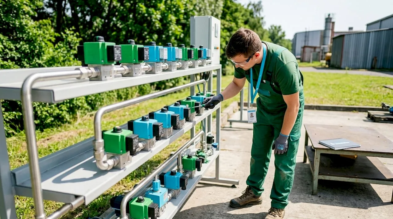
Three ports and two positions. The valve either supplies pressure to the outlet or vents the outlet. It is used to control single-cylinder actuators with spring return, for example for clamping fixtures or pneumatic flaps. The simplicity of design means a lower purchase price and a smaller installation space.
5/3-way valves
Five ports and three positions, with the middle position defining the system's behavior in the event of signal loss. This type is chosen when it is necessary to control movement in two directions while also defining a safe state in the event of a power failure. The middle positions are covered in more detail in a separate section below.
Overview of the most common types and their typical applications:
- 5/2-way solenoid valve: control of double-acting cylinders, assembly automats, pressing machines
- 3/2-way valve: single-cylinder drives with spring return, clamping fixtures, flaps
- 5/3-way valve with closed center: vertical axes, load holding, safety applications
- 5/3-way valve with exhaust center: horizontal axes requiring free movement in case of failure
- 5/3-way valve with pressure center: applications requiring pressure in both cylinder chambers in the rest position
- Proportional valves: continuous flow or pressure control, robotic applications, test stations
Multi-way valves in industry form the basis of every automated pneumatic system. Modern production lines are also increasingly using valve islands, which combine multiple valves on a common rail with a shared air supply and data bus for the PLC. The result is more compact wiring, simpler cabling, and faster replacement of a faulty valve without having to disconnect the entire system.
How to choose the center position for 5/3-way valves?
Choosing the center position is a safety decision, not just a technical preference. The valve's behavior upon loss of power or signal directly determines what happens to the actuator and any load it carries.
The three available center position variants differ fundamentally:
- Closed center: all ports are closed, the cylinder remains in its current position. Essential for vertical axes and applications where the load must not drop in the event of a power failure.
- Exhaust center: both cylinder chambers are vented, the piston can move freely. Suitable for horizontal axes where the operator needs to manually move the actuator during servicing.
- Pressure center: both chambers are pressurized, the cylinder is locked by air force. Used where a rigid hold without a mechanical brake is required.
Professional tip: Before selecting the center position, always perform a risk analysis according to ISO 13849. An unsuitable center position on a vertical axis with a closed exhaust center can cause an uncontrolled drop of the load in the event of a power failure.
The most common mistake is using an exhaust center on a vertical axis. In the event of a power failure, both chambers vent and gravity moves the piston uncontrollably. A closed center is essential for every application where there is a risk of a drop or uncontrolled movement in the event of signal loss. A pressure center, on the other hand, is suitable for clamping fixtures where clamping force must be maintained even without an active signal. The correct choice protects both the machine and the operator.
How to correctly size a pneumatic valve?
Valve sizing starts with the flow coefficient value Cv. This value expresses how much airflow the valve will pass at a given pressure drop. An undersized valve creates a bottleneck in the system and slows down the cylinder's movement even when all other components are correctly designed.
The correct sizing procedure includes these steps:
- Determine the cylinder bore and stroke, from which the air consumption per cycle is calculated
- Determine the required cycle time and derive the necessary flow rate in liters per minute from it
- Select a valve with a Cv value that covers the calculated flow with a reserve of approximately 20%
- Verify that the valve's connection thread matches the diameter of the supply piping
- Check the valve's maximum working pressure against the system's operating pressure
Professional tip: When calculating Cv, do not forget the pressure drop across the supply piping and fittings. The actual pressure at the valve inlet is usually 0.5–1 bar lower than the pressure at the compressor outlet, especially with long distribution lines.
The Cv value is critical for the resulting speed of movement and cycle reliability. Technicians who size a valve only by thread diameter without calculating flow rate regularly find that the cylinder does not reach the required speed even at full operating pressure. Testing the valve parameters directly on the machine before final assembly saves time during commissioning. Measuring the cycle time at different flow control valve settings reveals whether the valve is actually a bottleneck in the system.
How to maintain pneumatic valves and prevent failures?
The most common cause of valve failure is a dirty or wet air supply with solid particles. Contaminants cause seal corrosion, spool jamming, and short-circuiting of the solenoid coil. Prevention is straightforward and inexpensive compared to the cost of replacing a valve or an unplanned line stoppage.
Regular maintenance of pneumatic valves includes the following points:
- Checking and cleaning the FRL unit filter every week or according to the manufacturer's instructions. A clogged filter reduces pressure and lets contaminants pass further into the system.
- Draining condensate from the filter and air tank daily or automatically using an automatic drain valve.
- Checking the oil level in the automatic lubricator of the FRL unit. Insufficient lubrication accelerates wear of the spool seals.
- Visual inspection of the tightness of the supply piping and connecting fittings. Air leakage increases consumption and reduces the pressure at the valve inlet.
- Verifying the manual override function of the valve. Manual actuation without an electrical signal immediately shows whether the problem is mechanical or electrical.
Manual valve actuation is a key tool in fault diagnostics. A technician who manually actuates the valve and sees the actuator move knows that the problem is not mechanical, but electrical or in the control system. This simple test reduces diagnostic time to a minimum. Diagnosing valve problems takes less than 2 hours with proper maintenance and knowledge of the system. Investment in a quality FRL unit pays off in extended valve life and fewer unplanned stoppages.
Professional tip: When replacing a valve, always check the condition of the supply piping and fittings. A new valve in a contaminated system will fail just as quickly as the original one.
Servicing and cleaning pneumatic systems should be part of the planned preventive maintenance of every production line. A technician who knows the system and regularly checks the FRL units prevents most valve failures before they cause downtime.
Key Findings
Correct valve type selection, sizing according to the Cv value, and regular maintenance of FRL units are the three conditions for reliable operation of a pneumatic system.
| Point | Details |
|---|---|
| Most Common Valve Type | A 5/2-way solenoid valve is the standard for controlling double-acting cylinders in automation. |
| Center Position as a Safety Choice | A closed center is essential for vertical axes, while an exhaust center allows free movement during servicing. |
| Sizing According to Cv | An undersized valve slows down the cycle even at correct pressure; a 20% reserve above the calculated flow rate is the minimum. |
| Failure Prevention | A quality FRL unit with regular filter and automatic lubricator inspection prevents most valve failures. |
| Manual control | Manually actuating the valve during diagnostics immediately separates a mechanical fault from an electrical or control one. |
Field experience: what technicians overlook most often
Over years of working with pneumatic systems, I have found that most valve failures are not caused by a faulty component but by poor design or neglected maintenance. Technicians who arrive at a malfunctioning valve immediately reach for a multimeter and check the coil power supply. Yet it would be enough to try manual control. If the valve does not work mechanically even when operated manually, the problem lies in contamination or spool wear, not in the electrics.
The second most common mistake is underestimating the Cv value when designing a system. I see it repeatedly: cylinder of the correct diameter, correct pressure, but a valve selected based on thread size without calculating flow. The result is a slow cycle, which the technician then unnecessarily tries to solve by increasing pressure or replacing the cylinder. Yet it is enough to replace the valve with a type with a higher Cv.
The third area where mistakes are made is the choice of center position for 5/3-way valves. An exhaust center on a vertical axis looks like a reasonable choice on paper for easy manual positioning. In practice, this means that if power fails, the load will drop down. Pneumatic safety in industry requires that the choice of center position always be based on risk analysis, not on intuition or habit.
My recommendation is simple: before installing any valve, answer three questions. What movement does the valve control? What happens if power fails? Is the valve's flow sufficient for the required cycle speed? These three questions eliminate most problems before the machine is even started.
— Zdeněk
Pneumatic valves and components for industrial applications
Kompresory-vzduchotechnika offers industrial technicians a complete range of pneumatic components, from valves and FRL units to air hoses and accessories for compressed air distribution.
The entire range of pneumatics and hydraulics includes valves for standard as well as demanding industrial applications. The Kompresory-vzduchotechnika team provides technical advice on selecting a valve for a specific application, helps with sizing, and recommends suitable accessories. Technicians who are unsure about their selection can contact customer support directly on the website and get an answer to a specific technical question without unnecessary waiting.
Frequently asked questions
What is a 5/2-way solenoid valve?
A 5/2-way solenoid valve has five ports and two positions. The solenoid switches the air supply between both chambers of a double-acting cylinder and is the standard type for industrial automation.
How do pneumatic valves work in PLC systems?
The solenoid valve converts an electrical signal from the PLC into mechanical movement of the spool. This allows the PLC to directly control the direction, speed, and position of the pneumatic actuator.
Which center position is suitable for vertical axes?
For vertical axes, the closed center is the correct choice. In the event of a power failure, it closes all ports and the cylinder remains in its current position without the risk of the load falling.
Why does the valve slow down the cycle even at the correct pressure?
The most common cause is an undersized valve with an insufficient Cv value. The valve forms a bottleneck in the system and restricts air flow regardless of the operating pressure.
How often should FRL units be inspected?
The filter of the FRL unit should be checked weekly, and condensate should be drained daily or automatically. Regular inspection of the automatic lubricator and pipe tightness prevents most valve failures.
Recommended
- How pneumatics works: a complete guide for industry 2026
- Pneumatic tools in 2025: trends and innovations - Kompresory-Vzduchotechnika.cz
- Advantages of Pneumatic Tools 2026: 40% Longer Service Life - Kompresory-Vzduchotechnika.cz
- How air valves work: their key role and efficient solutions - Kompresory-Vzduchotechnika.cz

How to choose the right oil for a compressor: a guide 2026
In brief:
- The correct choice of compressor oil depends on the type of equipment, operating conditions and the chemical composition of the lubricant. Synthetic oils offer longer change intervals and lower energy consumption compared to mineral oil.
Compressor oil performs four basic functions: it lubricates moving parts, dissipates heat, seals clearances and captures contaminants. An incorrect choice of lubricant shortens bearing life, increases energy consumption, and in extreme cases causes seizure of the rotors or pistons. The choice of oil for an air compressor is governed by three key parameters: the type of base oil, the ISO VG viscosity grade, and the operating conditions of the specific equipment. This guide explains how to correctly select compressor oil, covering everything from chemical composition to change intervals and sample analysis.

What are the main types of compressor oils?
Compressor lubricating oils are divided into four basic categories according to the chemical composition of the base oil. Each category has different properties, different change intervals and different operating costs.
Mineral oil is the most widespread and cheapest option. It is produced by refining crude oil and contains natural impurities that accelerate oxidation at higher temperatures. The change interval for mineral oil ranges from 1,000 to 2,000 operating hours. This means a significantly higher frequency of service interventions compared to synthetic alternatives.
Synthetic PAO-based oil (polyalphaolefin) offers significantly better thermal stability and oxidation resistance. Change intervals reach 4,000–12,000 hours, and synthetic oils reduce the compressor's frictional resistance by 5–8%. Lower friction directly translates into reduced electricity consumption.
Synthetic POE-based oil (polyolester) is used mainly in refrigeration compressors and equipment operating with refrigerants. POE oils have excellent lubricating properties at low temperatures and are compatible with most elastomers. Their disadvantage is higher hygroscopicity, i.e. a tendency to absorb atmospheric moisture.
Ester oils combine the properties of PAO and POE. They are used in demanding industrial applications with extreme temperature fluctuations. They are more biodegradable than other synthetic base oils, which is an advantage in environmentally sensitive operations.
| Oil type | Change interval | Frictional resistance | Typical use |
|---|---|---|---|
| Mineral | 1,000–2,000 h | Higher | Light industry, DIY |
| Synthetic PAO | 4,000–8,000 h | Lower by 5–8% | Screw compressors |
| Synthetic POE | 4,000–12,000 h | Low | Refrigeration compressors |
| Ester-based | 6,000–12,000 h | Very low | Demanding industry |
In addition to the chemical base, oils for piston compressors must also comply with the DIN 51506 VDL specification. Ash-free oils of the VDL class (for example Paramo Mogul Komprimo VDL 100) reduce the formation of carbon deposits on the valves, extend service intervals and reduce the risk of having to clean the compressor head. For operations with high daily load, this is an economically advantageous solution.
Key properties to compare when selecting an oil:
- ISO VG viscosity class (most commonly ISO VG 46 or ISO VG 68 for screw compressors)
- Flash point (at least 200 °C for safe operation)
- Viscosity index (the higher, the more stable the viscosity is under temperature changes)
- Content of antioxidant and anti-corrosion additives
- Compatibility with seals and elastomers in the specific compressor
Reference overview of viscosity classes for piston compressors:
| ISO VG viscosity | Typical use | Note |
|---|---|---|
| ISO VG 32 | Light piston compressors, low temperatures | Suitable for cold environments |
| ISO VG 46 | Standard piston compressors, hobby and workshop use | Most commonly recommended class |
| ISO VG 68 | More powerful piston and two-stage compressors | Higher operating temperatures |
| ISO VG 100 | Heavy-duty industrial compressors, high load | As specified by the manufacturer |
Professional tip: Before switching from mineral to synthetic PAO oil, check the filters and oil channels. Synthetic oils have a higher detergent effect and release old deposits, which can clog filters during the first 200–500 hours of operation.
Cheap mineral oils carry hidden costs in the form of more frequent changes and lower energy efficiency. When calculating total operating costs, you need to include labor costs, equipment downtime, and energy consumption, not just the price of the lubricant itself.
How do operating conditions affect oil selection?
Compressor outlet temperature, intake air quality, and humidity are three factors that determine the suitable oil more than price or brand. Each of them affects the rate of lubricant degradation and the frequency of changes.
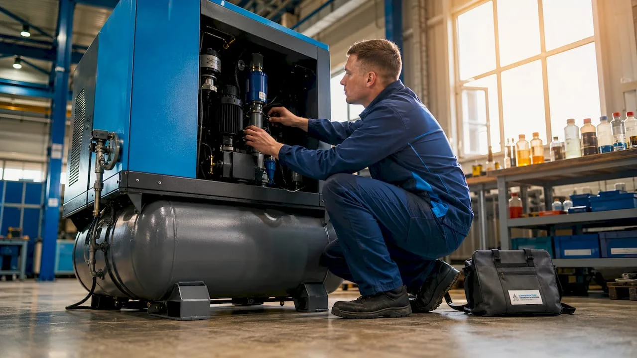
The effect of temperature on oil degradation
Temperature is the decisive factor affecting oil oxidation and its lubricating properties. As a general rule, every 10 °C above the recommended operating temperature doubles the rate of lubricant oxidation. Compressors operating at an outlet temperature above 90 °C require synthetic oil with a high viscosity index and strong antioxidant additives.
Modern compressors also have a safety feature: when the lubricating oil temperature reaches 93 °C, the machine automatically shuts down to prevent damage. Repeatedly reaching this threshold is not a sign that the machine is fine, but a symptom of a problem. The most common causes are a fouled oil cooler, a clogged air filter, or excessively high temperature in the compressor room.
Air quality and dustiness of the environment
A dusty environment accelerates oil contamination by solid particles. Abrasive impurities cause wear on bearings and piston rings. Under such conditions, oil change intervals need to be shortened and the frequency of air filter inspections increased.
Air quality factors affecting lubricant selection:
- Concentration of dust and solid particles in the intake air
- Presence of chemical vapors or aggressive gases
- Intake air temperature (higher temperature means lower air density and higher thermal load)
- Operating altitude (affects cooling efficiency)
Oil moisture and oxidation
High humidity in the intake air causes oil emulsification. Water in the oil reduces its lubricating ability and accelerates corrosion of metal surfaces. POE oils are more sensitive to moisture than PAO, so PAO or mineral oils with good hydrophobic properties are recommended for operations with high humidity. Emulsified, milky white oil indicates water contamination and requires immediate replacement regardless of operating hours.
Professional tip: If the compressor operates in an environment with temperatures below 5 °C, choose an oil with a lower ISO VG grade or a special winter formulation. Oil that is too thick during a cold start causes cavitation of the oil pump and insufficient lubrication of bearings in the first seconds of operation.
Adapting viscosity to operating conditions is a direct way of preventing premature wear. ISO VG viscosity is the most important parameter when selecting oil. Viscosity that is too low leads to bearing failure, while viscosity that is too high causes starting problems and increases energy consumption.
Procedure for correctly selecting and changing the oil in a compressor
Proper oil change requires preparation, adherence to the procedure, and compatibility checks. Improvisation at this step causes more failures than neglecting the oil change itself.
Step by step: oil change
- Warm up the compressor to operating temperature. Warm oil is thinner and drains better. Cold oil leaves up to 15% of the old lubricant in the tank.
- Shut down the compressor and release the pressure. Never open the oil tank under pressure.
- Drain the old oil through the drain valve. Let it drain for at least 10 minutes.
- Check the condition of the old oil. Dark color, cloudiness, or foam indicate contamination or oxidation.
- Replace the oil filter. Using an old filter with new oil negates the benefit of the change. A clogged filter restricts oil flow and increases the risk of insufficient lubrication during cold starts.
- Fill the new oil up to the mark on the dipstick. Overfilling causes foaming and oil leakage into the compressed air.
- Run the compressor for 5 minutes and check for leaks. Check the oil level after the first warm-up.
Oil compatibility and the risk of mixing
Mixing incompatible oils, for example PAG with POE, can create gel or sludge. This sludge quickly destroys the compressor bearings. Do not mix synthetic and mineral oils in one system either — their additive packages may react, form sludge, and clog oil channels. When switching from one type to another, thoroughly flush the system with clean oil according to the manufacturer's procedure. Also be careful when mixing oils of different brands with the same viscosity: the resulting properties will approach those of the weaker of the two oils, which can mean failure in demanding operation.
The most common mistakes when changing oil:
- Skipping the oil filter replacement when changing the lubricant
- Topping up a different type of oil into the remainder of the old one (mixing base oils)
- Overfilling the oil tank above the maximum mark
- Using oil with an incorrect ISO VG grade
Analyzing an oil sample every 2,000 hours of operation is an effective way to prevent bearing failure and compressor seizure. Laboratory analysis detects metal particle content, water, oxidation products, and contaminants before they cause a breakdown. This method is referred to as predictive maintenance based on oil condition.
Professional tip: When selecting an industrial compressor, always verify which type of oil the manufacturer specifies. Using a different lubricant may void the warranty, even if the oil is technically comparable.
What are the most common mistakes when choosing compressor oil?
Incorrect lubricant selection is one of the most common causes of premature compressor wear. Most mistakes stem from cost-cutting or lack of information.
The most common errors in practice:
- Using automotive engine oil. Engine oil contains additives intended for combustion engines, not for compressors. Automotive oil causes carbon deposits and rotor seizure after 500–800 hours of operation. This mistake is very widespread in practice, especially among users of piston compressors.
- Mixing different types of oils. Adding a different lubricant to the remaining old oil without verifying compatibility is a direct path to gel or sludge formation in the oil circuit.
- Failing to follow replacement intervals. Extending the replacement interval of mineral oil beyond 2,000 hours leads to oxidation of the lubricant and the formation of varnish on internal surfaces.
- Selecting oil based on price alone. The cheapest oil on the market may not meet the compressor manufacturer's requirements for viscosity or additive content.
"The right compressor oil is neither the cheapest nor the most expensive. It is the one that meets the equipment manufacturer's specifications, suits the operating conditions, and whose replacement intervals are actually followed. Every saving on lubricant comes back as a repair cost."
Selecting the oil for an air compressor according to the equipment manufacturer's recommendation is a basic condition for maintaining the warranty and reliable operation. Following the recommendations of both the oil manufacturer and the compressor manufacturer ensures long-term reliability and predictable operating costs.
How to monitor oil condition and when to plan a replacement?
Monitoring oil condition is the most effective way to prevent unplanned downtime. Regular checking of oil level and condition, including filter cleaning, has been proven to extend compressor service life. Before each start-up, check the oil level using the dipstick or sight glass and inspect oil seals and hoses for visible leaks. Every 250–500 operating hours, replace the oil filter and perform a visual assessment of oil quality.
Laboratory analysis of an oil sample monitors the following parameters:
| Parameter | What it indicates | Limit value |
|---|---|---|
| Water content | Condensation, cooler leak | Above 0.1% |
| Viscosity at 40 °C | Oil degradation or dilution | Deviation above 10% from the new value |
| Fe, Cu, Al content | Bearing and piston wear | According to the manufacturer's standard |
| Total acid number (TAN) | Oxidation and acid formation | Above 2.0 mg KOH/g |
| Solid particle content | Environmental contamination | ISO 4406 class |
Regular oil analysis makes it possible to detect metal fatigue or coolant ingress before a failure occurs. The analysis results serve as a basis for deciding whether to extend or shorten the oil change interval. Besides laboratory analysis, the most reliable diagnostic tool at hand is hearing: a properly lubricated and adjusted compressor runs quietly and evenly, and any change in the sound profile deserves immediate attention. We recommend keeping an oil change log recording operating hours, the lubricant used, and the condition of the oil at the time of change — this will save more time than any other tool during later diagnostics.
Extending oil change intervals significantly reduces operating costs and minimizes downtime, provided the correct type of synthetic oil is used. Switching from mineral to synthetic PAO oil combined with regular sample analysis can reduce the number of oil changes per year by more than half. This has a direct impact on labor, lubricant, and equipment downtime costs. Choosing the right lubricant and saving energy with a compressor go hand in hand — a screw compressor with degraded oil consumes several percent more electrical energy for the same output than the same machine with fresh lubricant.
Key Findings
Selecting the correct compressor oil requires knowledge of the equipment type, operating conditions, and the chemical composition of the lubricant, with synthetic oils based on PAO or POE offering significantly lower total operating costs than mineral alternatives.
| Point | Details |
|---|---|
| Oil type determines change intervals | Synthetic PAO lasts 4,000–12,000 h, mineral oil only 1,000–2,000 h. |
| ISO VG viscosity is a key parameter | ISO VG 46 is the most common grade for standard reciprocating compressors; using the wrong grade causes bearing failure or starting problems. |
| Automotive oil has no place in a compressor | It causes carbon deposits and rotor seizure after 500–800 hours. |
| Mixing oils is prohibited | PAG with POE forms a gel that destroys bearings within a few hours of operation. |
| A temperature of 93°C is the critical limit | Modern compressors automatically shut down at this temperature; repeated shutdowns indicate a problem in the lubrication or cooling system. |
| Sample analysis every 2,000 hours prevents failures | Laboratory analysis reveals metal wear and contamination before a failure occurs. |
Practical experience: what I've learned about choosing oil
Over years of working with various types of compressors, I've reached one conclusion that holds true without exception. The greatest damage is caused not by the wrong oil, but by the correct oil used at the wrong time or mixed with a different type of lubricant.
In practice, I've seen damaged machines where the last oil change took place three years ago, even though the machine had logged thousands of hours in the meantime. The argument was always the same: the oil level was within normal range. Overheating of the lubricating oil is one of the most recurring causes of unplanned repairs. The automatic shutdown at 93°C is a protection that works, but repeatedly reaching that limit means the system is operating at the edge of its capabilities. I always look for the cause: a clogged oil cooler, a blocked air filter, or too high an ambient temperature in the machine room.
I never rely on the assumption that "the same viscosity will do". Compressor manufacturers test their machines with specific oils and certifications. A replacement oil of a different brand with the same viscosity may not have the same antioxidant or anticorrosive additives. In demanding operation, where the compressor runs 20 hours a day, this difference becomes apparent within a few months.
My recommendation for operators of screw compressors is clear: invest in synthetic PAO oil and set up regular sample collection. The initial costs are higher, but the overall operating costs are lower and downtime is predictable. For piston compressors in light industry or workshops, a quality mineral oil with strict adherence to the change interval is a sufficient choice.
One practical detail rarely mentioned in manuals: when switching from mineral to synthetic oil, perform the first synthetic oil change after 500 hours, not after the standard interval. Synthetic oil releases old deposits, and the first fill will become contaminated faster than the standard interval would suggest.
— Zdeněk
Oils and lubricants for compressors at Kompresory-vzduchotechnika.cz
Choosing the right lubricant is easier with expert support. Kompresory-vzduchotechnika.cz offers technical advice for selecting oil based on the type of compressor, operating conditions and required change intervals.
The range includes lubricants for piston and screw compressors, mineral and synthetic oils of ISO VG 46 and ISO VG 68 classes, and accessories for oil changes and analysis. The expert team at Kompresory-vzduchotechnika provides consultations for industrial operations as well as individual users. The entire pneumatics and hydraulics range is available online with the option of technical consultation before ordering.
Frequently Asked Questions
What oil should be used in a screw compressor?
For screw compressors, a PAO-based synthetic oil of ISO VG 46 or ISO VG 68 class is recommended according to the manufacturer's specification. Synthetic oils offer change intervals of 4,000–12,000 hours and reduce frictional resistance by 5–8%.
Can engine oil be used instead of compressor oil?
Engine oil does not belong in a compressor. It contains additives for combustion engines that cause carbon deposits and rotor seizure after 500–800 hours of operation.
How do I know it's time to change the oil in my compressor?
The oil should be changed when the manufacturer's recommended interval is reached, when the lubricant becomes cloudy or darkens, when it foams, or when an increased content of metal particles is found in a sample analysis. Milky white (emulsified) oil indicates water contamination and requires immediate replacement.
Can different types of compressor oils be mixed?
Mixing different types of oils is prohibited. Combining PAG and POE oils forms a gel that destroys the compressor bearings within a few hours of operation. Do not mix synthetic with mineral oil either.
How often should oil analysis be performed on a compressor?
Analysis of an oil sample every 2,000 operating hours is the standard frequency for industrial compressors. Laboratory analysis reveals contamination, oxidation, and metal wear before a failure occurs.
Recommended
- Factors for selecting an industrial compressor: a 2026 guide - Kompresory-Vzduchotechnika.cz
- Basic requirements for a compressor room: guide 2026 - Kompresory-Vzduchotechnika.cz
- Saving energy with a compressor: an expert guide 2026 - Kompresory-Vzduchotechnika.cz
- A list of safety rules for working with a compressor in automotive 2026 - Kompresory-Vzduchotechnika.cz

An overview of compressor filters for industry and construction
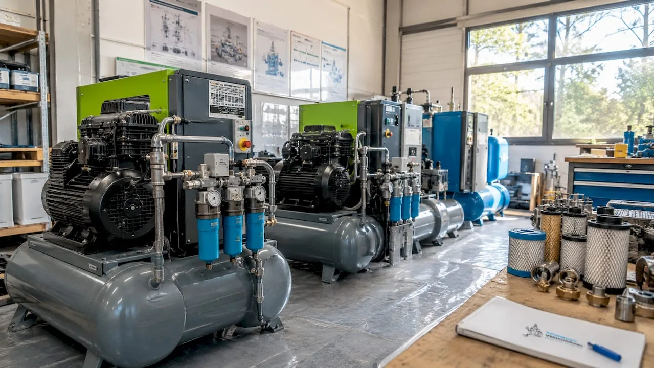
In brief:
- Compressor filters remove contaminants from compressed air and protect equipment and production processes. The most common types are coalescing filters, pre-filters, after-filters, activated carbon filters, and sterile filters, with the selection depending on the type of contamination and operating conditions. Proper filtration according to ISO 8573-1 requires a multi-stage system with differential pressure monitoring for efficient operation and energy savings.
A compressor filter is a device designed to remove contaminants from compressed air, with each type addressing a different kind of contamination. Proper filtration protects pneumatic tools, production lines, and final products from oil, moisture, dust, and gases. The ISO 8573-1 standard defines compressed air purity classes and sets measurable limits for solid particles, water, and oil. An overview of compressor filters is therefore not just a catalogue list, but a practical basis for selecting the right solution for a specific operation.
1. Overview of compressor filters: main types and their function
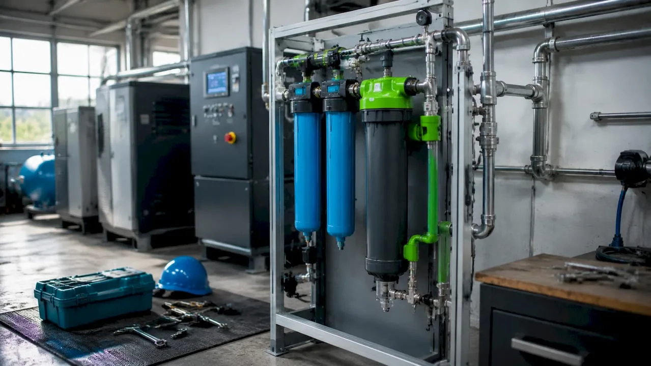
Filtration systems for compressors are divided into several basic categories according to the cleaning mechanism and their position in the system.
Mechanical (particulate) filters are the most widespread and widely available technology. Air passes through a fibrous or membrane medium that captures solid particles above a certain size. They are divided into coarse pre-filters (capturing particles above 5–40 microns) and fine filters (from 1 micron, in some designs down to 0.01 micron). However, they do not address oil mist, oil vapors, or moisture. The compressor's intake filter is the first line of defense for the entire system, and its replacement is the cheapest preventive measure in the whole compressor station, since a clogged intake filter directly increases the compressor's power consumption.
Coalescing filters are the most common type of fine filtration in industrial practice. They work on the principle of coalescence of tiny oil or water droplets: small droplets are captured on a fibrous medium, merge into larger drops, and flow down by gravity into a collection container. Filtration efficiency is 0.01–1 micron, which is essential for protecting pneumatic tools and sensitive production processes. They meet the ISO 8573-1 requirements for class 1 or 2 for oil.
Pre-filters are installed before the refrigerated dryer. They protect the dryer by removing moisture, oil, and larger contaminants before the air enters the more sensitive parts of the system. Without a pre-filter, the dryer becomes clogged faster and its service life decreases.
After-filters operate downstream of the dryer. They capture fine contaminants released by the dryer or that pass through the previous stage. The efficiency of after-filters reaches the same range of 0.01–1 micron as coalescing filters, but their role is supplementary.
Activated carbon filters remove gaseous pollutants, oil vapors, and odors. They work on the principle of adsorption, where contaminant molecules bind to the surface of the activated carbon. They are used where coalescing filters are not sufficient, for example in the food industry, pharmaceuticals, or painting. Their efficiency depends on the temperature and humidity of the environment. A saturated carbon cartridge stops filtering without any visible warning, so replacement intervals must be observed regardless of the filter's visual condition.
Special sterile filters are used in applications with the highest requirements for air purity, such as pharmaceutical or food production. They capture bacteria and microorganisms and meet strict hygiene standards.
2. Filter efficiency and technical parameters
Filtration efficiency is expressed in microns and indicates the smallest particle size that the filter will capture. Coalescing filters cover a range of 0.01–1 micron, pre-filters cover the coarser fraction above 1 micron, and sterile filters capture particles below 0.01 micron.
Operating temperature significantly affects the performance of activated carbon filters. At temperatures above 35–40 °C, their efficiency drops sharply, causing oil vapor to penetrate the system. Activated carbon filters therefore require placement in a cool, ventilated area.
Pressure drop is the most reliable indicator of filter condition. Monitoring the pressure drop allows the filter element to be replaced at the right time, before it becomes fully clogged. A clogged filter increases the compressor's energy consumption and reduces air flow.
Professional tip: Install a pressure gauge before and after each filter. A pressure difference above 0.5 bar indicates that the element needs to be replaced. Do not wait for visible contamination or a fixed time interval.
| Filter type | Efficiency (microns) | Typical application | Temperature sensitivity |
|---|---|---|---|
| Pre-filter | 1–40 | Dryer protection, coarse contaminants | Low |
| Coalescing | 0,01–1 | Oil, moisture, fine aerosols | Medium |
| Post-filter | 0,01–1 | Final purification after the dryer | Low |
| Activated carbon | Gaseous substances | Odours, oil vapours | High (above 35–40 °C) |
| Sterile | Below 0.01 | Pharmaceuticals, food industry | Medium |
3. Comparison of key filter characteristics
The choice of the correct filter depends on a combination of four parameters: filtration efficiency, resistance to operating conditions, maintenance costs, and recommended use.
| Characteristics | Pre-filter | Coalescing | Activated carbon | Sterile |
|---|---|---|---|---|
| Filtration efficiency | Coarse (above 1 µm) | Fine (0.01–1 µm) | Gaseous substances | Very fine (below 0.01 µm) |
| Moisture resistance | High | High | Low | Medium |
| Temperature resistance | High | Medium | Low (above 35–40 °C) | Medium |
| Cartridge replacement costs | Low | Medium | Medium to high | High |
| Replacement frequency | According to pressure drop | According to pressure drop | According to temperature and load | According to application |
| Recommended use | All operations | Industry, painting, pneumatics | Food industry, pharmaceuticals | Pharmaceuticals, medicine |
The following overview shows which contaminants individual filter types actually capture and which oil purity classes according to ISO 8573-1 can be achieved as a result:
| Filter type | Solid particles | Oil/aerosols | Odors | ISO 8573 Class (oil) |
|---|---|---|---|---|
| Mechanical (coarse) | Yes | No | No | 4–5 |
| Mechanical (fine) | Yes | Partially | No | 3–4 |
| Coalescing | Yes | Yes | No | 1–2 |
| Activated carbon | No | Yes (vapors) | Yes | 1 |
Pressure drop and filter clogging significantly affect the operating efficiency and energy consumption of the compressor. A clogged filter does not act as a safeguard, but as a brake on the entire system.
An effective filtration system reduces the rejection rate and increases production reliability. This applies especially in industries where air contamination directly affects the quality of the final product.
4. How to Choose the Right Filter for Industrial or Construction Use
Filter selection begins with an analysis of contamination in the specific operation. A paint shop requires a different approach than a concrete plant, and a pharmaceutical facility requires yet another.
Basic selection criteria:
- Type of contamination: Oil and moisture require a coalescing filter. Dust and coarse impurities are handled by a pre-filter. Odors and gaseous substances are removed by an activated carbon filter.
- Operating temperature: Activated carbon filters cannot be used in spaces with temperatures above 35–40 °C without additional cooling.
- Required purity class: The ISO 8573-1 standard defines classes 0–6 for solid particles, water, and oil. Class 1 for oil means a content below 0.01 mg/m³, while class 4 means below 5 mg/m³.
- Air flow (l/min or m³/h): The filter must match the rated flow of the compressor. An undersized filter increases pressure drop and reduces the performance of the entire system.
- Placement in the line: The pre-filter belongs before the dryer, the post-filter after the dryer, and the activated carbon filter at the end of the line.
- Availability of replacement elements and service support: A cheap filter with an expensive or hard-to-find element may, over a 3–5 year horizon, be more costly than a premium solution with readily available parts.
Multi-stage filtration combines a pre-filter, a main coalescing filter, and optionally an activated carbon filter. This approach meets the strict ISO 8573-1 standards and minimizes the risk of contaminants entering sensitive applications.
Recommendations by type of operation:
- Engineering and automotive (general): pre-filter + fine mechanical filter, sufficient for protecting pneumatic tools and valves.
- Paint shops and surface treatment: pre-filter + coalescing filter + activated carbon, meets class 1 requirements according to ISO 8573.
- Food and pharmaceutical industry: multi-stage filtration with coalescing and carbon stages, possibly a sterile filter.
- Welding and foundries: robust pre-filters with high solid particle retention capacity.
Professional tip: When designing a filtration system, allow for a flow reserve of at least 20%. Operating conditions change, and an undersized filter will cause a pressure drop that increases the operating cost of the entire line. In case of high dust content, choose filter media made of polyester fabric or pleated cartridges, which can be repeatedly cleaned with compressed air or water.
The most common mistakes when selecting a filter:
- Using a single filter where multi-stage filtration is required.
- Underestimating the effect of temperature on activated carbon filters.
- Selecting a filter without regard to flow rate and pressure losses.
- Neglecting regular checks of the pressure drop.
Investment in quality multi-stage filtration typically pays off within 12–24 months thanks to savings on maintenance and reduced downtime. This is a measurable economic argument, not just a technical recommendation.
When selecting a compressor for demanding industrial operations, it is also advisable to consider the criteria for choosing an industrial compressor, where filtration plays a key role in the overall system design.
5. Maintenance of compressor filters and failure prevention
Regular filter maintenance directly determines the service life of the entire pneumatic system. A neglected filter not only causes poorer air quality but also damages valves, cylinders, and tools downstream.
Maintaining filtration systems based on the actual pressure drop significantly prevents costly repairs. Fixed time intervals for element replacement are less accurate than monitoring the actual condition of the filter.
Recommended maintenance procedure:
- Daily visual inspection of the condensate and oil collection bowl.
- Weekly pressure drop reading from the pressure gauges before and after the filter. An increase above 0.2 bar indicates the onset of clogging, a difference above 0.5 bar requires element replacement.
- Regular condensate draining from the collection bowls, ideally using an automatic condensate drain.
- Filter element replacement when the recommended pressure drop is exceeded or at the latest once a year; typically every 6 to 12 months, shorter in dusty environments.
- Service records: replacement date, element type, measured pressure drop values.
- Use original spare parts. Non-original elements may not meet the declared filtration class and may cause complaints or malfunctions.
Activated carbon filters require special attention. With prolonged exposure to temperatures above 35–40 °C, they lose efficiency without this being visible. Regular element replacement according to the manufacturer's recommended interval is therefore mandatory, not optional.
Professional tip: When planning maintenance, take seasonal fluctuations into account. In winter, more moisture condenses in the piping and filters clog faster, so adjust inspection intervals to the season, especially for intake filters and condensate drains.
An overview of the most common mistakes in filter maintenance can also be found in the article on the most common mistakes when using compressors, which describes the specific effects of neglected filtration on operation.
Key Takeaways
Proper compressed air filtration according to ISO 8573-1 requires a multi-stage system with a prefilter, coalescing filter, and optionally an active carbon filter, with pressure drop being the main indicator of the condition of each stage.
| Point | Details |
|---|---|
| Multi-stage filtration | The combination of a prefilter, coalescing filter, and active carbon filter meets ISO 8573-1. |
| Pressure drop as an indicator | A pressure difference above 0.5 bar indicates the need to replace the filter element. |
| Temperature limit of active carbon | Active carbon filters lose effectiveness at temperatures above 35–40 °C. |
| Flow rate reserve | When designing, allow for a flow rate reserve of at least 20%. |
| Return on investment | Quality multi-stage filtration pays for itself within 12–24 months through savings on maintenance. |
| Selection by application | The filter type must correspond to the type of contamination, flow rate and required cleanliness class ISO 8573-1. |
Practical experience: what filtration actually determines
I have worked with compressor systems for many years and repeatedly see the same pattern. The operation invests in a quality screw compressor, but treats filters as a secondary item. The result is predictable: damaged valves, contaminated products and unplanned downtime. Problems with production quality or complaints are traced back precisely to a neglected filtration system.
The biggest mistake I see is relying on a fixed time interval for element replacement. A filter in a dusty paint shop clogs three times faster than a filter in a machine room with clean air. The pressure drop tells the truth, the schedule does not.
Activated carbon filters are an underrated category. In the food or pharmaceutical industry they are irreplaceable, but during summer months in an unventilated compressor room they stop working without anyone noticing. Placing the filter in a cool location is not a detail, it is a condition for proper function.
I recommend that every operation keep a simple record of pressure drops with the date of reading. A table on paper or in Excel is enough. After six months you will have data that shows the actual service life of the elements under your conditions. This is more accurate than any general guideline.
— Zdeněk
Filters and accessories for compressed air treatment from Kompresory-vzduchotechnika
Kompresory-vzduchotechnika offers a complete range of filters and devices for compressed air treatment, from simple pre-filters to multi-stage filtration assemblies for demanding industrial operations.
For standard industrial applications, the air treatment units are suitable, combining filtration, pressure regulation and lubrication in one compact unit. For operations requiring compliance with the ISO 8573 standard, Kompresory-vzduchotechnika offers a filtration program according to ISO 8573 with certified components. The technical team is available for consultation on selecting the right filtration solution according to specific operating conditions.
Recommended
- Factors for selecting an industrial compressor: a 2026 guide - Kompresory-Vzduchotechnika.cz
- Basic requirements for a compressor room: guide 2026 - Kompresory-Vzduchotechnika.cz
- List of advantages of screw compressors for industry - Kompresory-Vzduchotechnika.cz
- Checklist of accessories for compressors: a guide for technicians - Kompresory-Vzduchotechnika.cz

What is pneumatic sealing and how does it work in practice
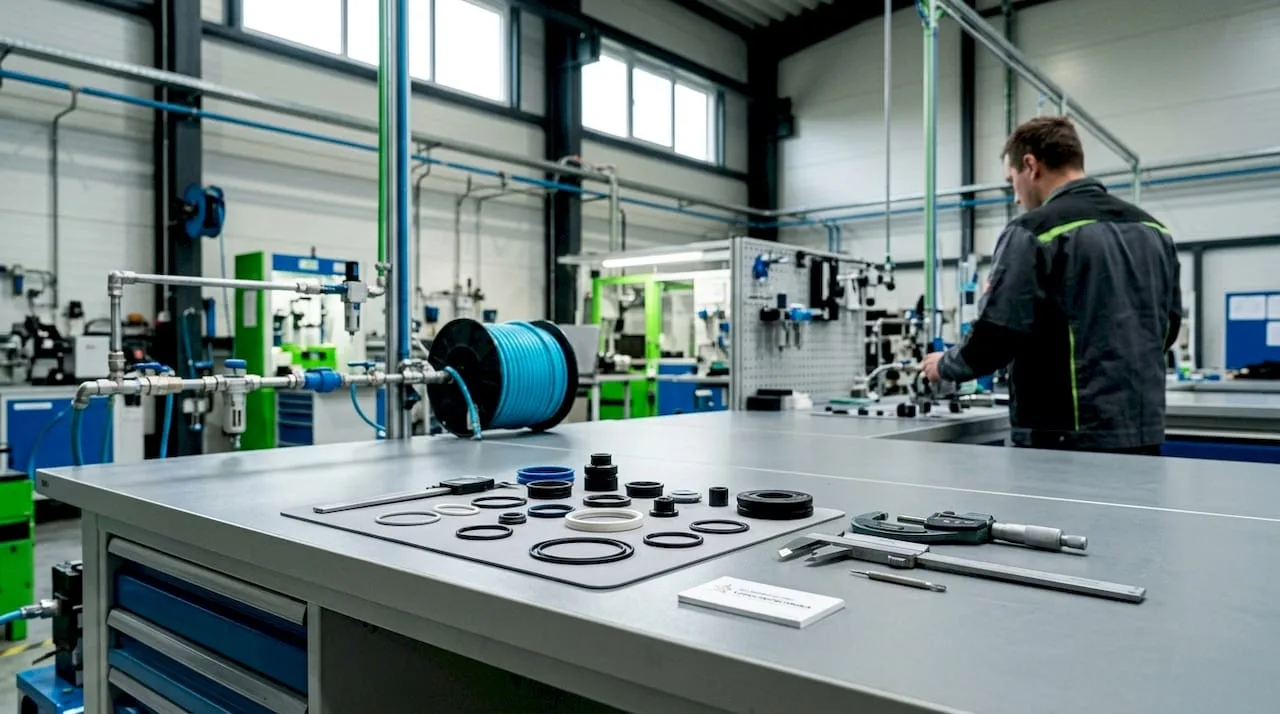
In brief:
- A pneumatic seal creates an impermeable barrier in the system through elastic deformation and contact pressure. A properly designed seal prevents leakage of compressed air and maintains pressure throughout the service life of the equipment. The key parameter is the compression ratio, which must correspond to the type of seal and the operating load.
A pneumatic seal is an elastomeric element that creates an impermeable barrier in a pneumatic system through controlled deformation and contact pressure. A properly designed seal prevents leakage of compressed air and maintains pressure at the operating level throughout the service life of the equipment. The key parameter is the compression ratio: for static connections, the range of 15–30% applies, for dynamic reciprocating seals 10–15%, and for rotary applications 3–8%. These values are not a recommendation but a technical requirement. Deviation from them leads to premature wear or leakage. Kompresory-vzduchotechnika offers expert advice on selecting seals for specific operating conditions.
What is a pneumatic seal and what is the principle of its function?
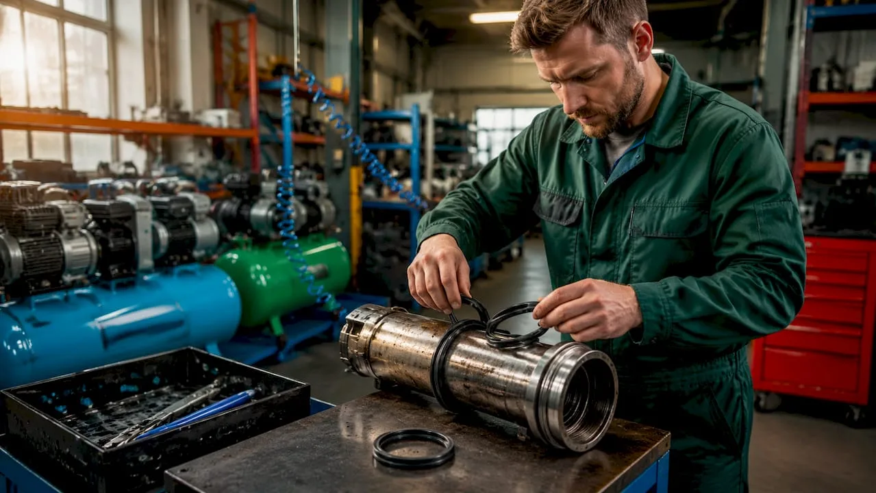
A pneumatic seal works on the principle of elastic deformation of the material under pressure. During installation, the seal is compressed by a defined proportion of its cross-section. This deformation creates contact pressure on the adjacent surfaces, which prevents the passage of compressed air. The seal is not a passive element. It actively responds to changes in system pressure and design clearance, so its behavior is dynamic.
The difference between static and dynamic sealing lies in the movement of the contact surfaces. Static seals operate between fixed parts, for example in pipe joints or cylinder heads. Dynamic seals seal moving components, such as piston rods or rotating shafts. Each type requires a different compression ratio and a different material. Confusing these categories is one of the most common causes of premature failure.
The Poisson's ratio of the elastomer directly affects how the seal behaves under compression. For NBR material, it reaches a value of approximately 0.47, which means 4.7% radial expansion at 10% axial compression. This radial expansion provides the sealing force within the cylinder or groove. Knowledge of this parameter is essential when designing a seal.
How do materials affect the properties of pneumatic seals?
The choice of elastomer determines the temperature resistance, chemical compatibility, and service life of the seal. The wrong material means rapid failure and higher maintenance costs. Below is an overview of the most commonly used materials and their key properties.
| Material | Temperature range | Main advantage | Typical application |
|---|---|---|---|
| NBR (nitrile rubber) | –30 to +100 °C | Resistance to oils and fuels | Hydraulics, pneumatics, automotive |
| PU (polyurethane) | 0 to +60 °C | High resistance to wear | Piston rods, linear actuators |
| HNBR (hydrogenated NBR) | –30 to +150 °C | Resistance to temperature and chemicals | Industrial machinery, compressor technology |
| FKM (Viton) | –20 to +200 °C | Resistance to aggressive media | Chemical industry, high-temperature applications |

NBR is the most widely used material for standard pneumatic applications. Polyurethane is suitable for temperatures in the range of 0–60 °C and excels in wear resistance, which is why it is used in linear actuators with high stroke frequency. HNBR replaces NBR where temperatures exceed 80 °C or where more aggressive substances are present. FKM is the choice for chemically demanding environments and temperatures exceeding 150 °C.
The geometry of the seal affects sealing force and friction to the same extent as the material. The O-ring is the simplest shape, but for high pressures or abrasive environments, X-rings, U-cups, or special profile seals are used. Asymmetric profiles reduce friction while maintaining sealing force. Integrated wipers remove contaminants from the piston rod and extend the service life of the entire system.
Professional tip: When selecting a material, always base your decision on the highest operating temperature and the most aggressive medium in the system. The seal must handle the worst-case conditions, not the average ones.
What are the main causes of pneumatic seal failure?
In most cases, seal failure has a specific technical cause, not a random character. The most common damage mechanism is the extrusion of material into the design clearance, known in English as nibbling. This phenomenon is caused by a combination of system pressure and the gap between the piston and the cylinder.
A seal designed for a pressure of 100 PSI and a clearance of 0.005" fails quickly when the pressure is increased to 150 PSI or the clearance is widened to 0.010". The seal material is repeatedly pressed into the gap and mechanically abraded. The result is leakage, elastomer fragments in the system, and reduced service life.
Main causes of pneumatic seal failure:
- Nibbling (extrusion into clearance): a combination of high pressure and excessive design clearance; the most common cause of failure in dynamic applications
- Excessive compression: exceeding the recommended compression ratio leads to overheating and degradation of the elastomer
- Wrong material: using NBR in environments with temperatures above 100 °C or in contact with aggressive chemicals
- Insufficient lubrication: dry friction on the piston rod accelerates seal wear even when the correct material is used
- Damage during installation: cutting or twisting the seal during installation causes immediate or early failure
- Contamination: solid particles in the system cause abrasive wear of the sealing surfaces
Dynamic pressure surges are more dangerous than static overpressure. Repeated pressure pulses cause the seal to vibrate in the groove and accelerate nibbling. The effect of variable pressure on the seal must therefore be taken into account already at the system design stage, not only after the first failure.
Professional tip: When analyzing damaged seals, always measure the actual clearance between the piston and the cylinder. Wear on sliding surfaces gradually increases the clearance, so a seal designed for a new machine may no longer be suitable after two years of operation.
How to correctly install and maintain pneumatic seals?
Correct installation and regular maintenance extend seal life significantly more than the choice of a more expensive material alone. Precise adherence to compression ratios is more important than the material itself in dynamic applications. Excessive compression leads to overheating and degradation of the elastomer, while insufficient compression leads to leakage.
Correct installation and maintenance procedure:
- Measure the groove and the seal cross-section before installation. Verify that the compression ratio matches the type of application: 15–30% for static seals, 10–15% for dynamic reciprocating seals.
- Apply a suitable lubricant to the seal and to the contact surfaces. For pneumatic applications, silicone or mineral lubricants compatible with the elastomer are used. Lubrication during assembly reduces friction and prevents damage during initial start-up.
- Install the seal without twisting it. For O-rings, check that the seal is not folded or twisted in the groove. A twist of 5° reduces the sealing force and causes uneven wear.
- Check the clearance between moving parts. The clearance must match the design value. Worn sliding surfaces must be repaired or replaced before installing a new seal.
- Set the operating pressure to the design value. Operation above the rated pressure accelerates nibbling and shortens seal life.
- Establish inspection intervals. For standard applications, inspect the seal at every scheduled shutdown. For critical assemblies, set shorter intervals or use condition monitoring.
Lubrication has specific requirements in pneumatics. Too much lubricant contaminates the system and can damage valves or sensors. Too little lubricant causes dry friction. A detailed overview of lubrication procedures for pneumatic systems is provided by the lubrication guide for technicians. Proper service procedure also includes cleaning the grooves of old seal residue and inspecting the piston rod surface for scratches or corrosion.
Where are pneumatic seals used in industry?
Pneumatic seals in industry are present in practically every sector that works with compressed air. The automotive industry is one of the largest users: pneumatic cylinders operate clamps, fixtures, and assembly lines, where seals must withstand millions of cycles. The food industry requires food-contact approved materials, typically silicone or EPDM elastomers. Mechanical engineering and automation use seals in linear actuators, rotary actuators, and pneumatic valves.
Modernized pneumatic seals in demanding conditions increase machine reliability by 40–70% and extend service intervals from the original 3–6 months to 2–3 years. This extended lifespan directly reduces maintenance costs and unplanned downtime. Advanced seals with asymmetric profiles and integrated wipers handle pressures up to 16 bar without damaging the backup structures.
| Industry | Typical application | Recommended material | Benefit of modernization |
|---|---|---|---|
| Automotive | Assembly lines, clamps | NBR, PU | Extended intervals to 2 years |
| Food industry | Filling and packaging machines | Silicone, EPDM | Compliance with hygiene standards |
| Chemical industry | Valves, pumps | FKM (Viton) | Resistance to aggressive media |
| Mechanical engineering | Linear actuators, cylinders | PU, HNBR | Reduction of friction and wear |
| Energy sector | Pneumatic valve actuators | HNBR, FKM | Reliability at high temperatures |
Future development is moving toward the integration of seals with condition monitoring. Pressure and vibration sensors detect incipient leakage before it causes a failure. This approach shifts maintenance from reactive to predictive and further extends service intervals. Effective servicing of pneumatic systems, including proper seal care, is described in the service guide on the Kompresory-vzduchotechnika website.
Key findings
Pneumatic sealing works reliably only when the material, compression ratio, and design clearance correspond to the specific operating conditions.
| Point | Details |
|---|---|
| Compression ratio | Static seals require 15–30%, dynamic reciprocating seals 10–15%, rotary seals 3–8%. |
| Material selection | PU for 0–60 °C, HNBR for temperatures above 80 °C, FKM for aggressive chemical environments. |
| Nibbling as the main risk | A combination of pressure above the design value and increased clearance causes mechanical extrusion and seal failure. |
| Benefit of modernization | Advanced seals increase machine reliability by 40–70% and extend service intervals to 2–3 years. |
| Lubrication and assembly | Proper lubrication during assembly and clearance inspection are just as important as material selection. |
Practical experience: what technical documentation doesn't tell you
I have worked with pneumatic systems for many years and repeatedly run into the same problem. Technicians pay great attention to selecting the seal material, but underestimate the compression ratio and design clearance. Yet these two parameters are exactly what determines whether a seal lasts one year or three months.
The most common mistake I see in practice is using the seal from a new machine as a replacement part after two years of operation. The sliding surfaces wear, the clearance increases, and a seal that was originally correctly designed starts to nibble. The result is a mysterious leak with no obvious cause. The solution is simple: every time you replace a seal, measure the actual clearance and compare it with the design value.
The second thing that surprises me is underestimating lubrication. Silicone lubricant costs nothing during assembly compared to the cost of unplanned downtime. Yet technicians skip it because "it worked before without it." It worked, but for a shorter time.
Upgrading seals to advanced types with asymmetric profiles or integrated scrapers is always worthwhile when the machine is part of a critical production line. The investment in a better seal pays off with the first downtime avoided. I see the future in predictive monitoring, but the foundation remains proper selection and installation. Without that, no sensor will help.
— Zdeněk
Pneumatic accessories and tubes from Kompresory-vzduchotechnika
A correctly selected seal needs a high-quality compressed air distribution system. A leaking or unsuitable pipeline negates even the best seal in the cylinder.
Kompresory-vzduchotechnika offers a complete range of compressed air tubes in diameters of 15–28 mm, suitable for industrial distribution as well as smaller workshops. The offer also includes air treatment units for pressures up to 10 bar, which maintain air quality and protect seals from contamination. The expert team at Kompresory-vzduchotechnika provides technical advice when selecting accessories for a specific application. Contact us for a consultation on your pneumatic system.
Frequently Asked Questions
What is pneumatic sealing and what is it used for?
A pneumatic seal is an elastomeric element that creates an impermeable barrier in a pneumatic system through controlled deformation and contact pressure. It prevents the leakage of compressed air and maintains operating pressure in pneumatic cylinders, valves, and actuators.
What compression ratio is correct for dynamic seals?
For dynamic reciprocating seals, a compression ratio of 10–15% applies, while for rotary applications it is 3–8%. Exceeding these values leads to overheating and premature wear of the elastomer.
What causes seal nibbling?
Nibbling occurs due to a combination of high system pressure and excessive design clearance between the piston and the cylinder. The seal material is repeatedly pressed into the gap and mechanically abraded, leading to leaks and failure.
What sealing material should be chosen for temperatures above 100 °C?
For temperatures above 80 °C, HNBR is suitable; for temperatures exceeding 150 °C or for aggressive chemical environments, FKM (Viton) is used. NBR is not suitable for these conditions.
How does seal modernization affect machine reliability?
Modernized pneumatic seals increase machine reliability by 40–70% and extend service intervals from 3–6 months to 2–3 years. Advanced types with asymmetric profiles withstand pressures up to 16 bar without damage.
Recommended
- What is pneumatic lubrication: a guide for technicians - Kompresory-Vzduchotechnika.cz
- How pneumatics works: a complete guide for industry 2026
- I.e. pneumatic connection: types, functions and practice - Kompresory-Vzduchotechnika.cz
- How fluctuating pressure affects the efficiency of pneumatic systems - Kompresory-Vzduchotechnika.cz

The Role of IoT in Pneumatic Systems: A Guide for Technicians
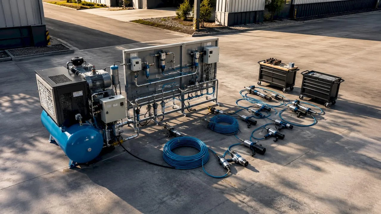
In brief:
- IoT in pneumatics connects components through sensors and protocols to automate monitoring and maintenance. IIoT deployment increases system reliability by 40 to 60 percent and reduces energy consumption by 25 to 35 percent. The key to success is the right protocol selection, an accurate data model, and gradual integration into production.
The role of IoT in pneumatic systems is defined as the connection of physical components through intelligent sensors, communication protocols, and edge computing for automated monitoring, control, and predictive maintenance. In industrial practice, this technology is referred to as IIoT (Industrial Internet of Things), with IIoT differing from consumer IoT mainly in scalability, interoperability, and low latency. IIoT deployment in pneumatics brings demonstrable results: energy savings reach 25–35%, and system reliability increases by 40–60%. These figures are not theoretical. They come from real industrial deployments where sensors, digital twins, and correctly selected protocols have replaced reactive maintenance with systematic control.
How IoT sensors and protocols work in pneumatic systems
The foundation of every intelligent pneumatic system consists of three types of sensors: pressure, flow, and temperature. Each type serves a different function and generates a different data stream.
- Pressure sensors measure operating pressure in piping and valve blocks. A deviation from the set value indicates a leak or seal wear.
- Flow sensors monitor air consumption in real time. Modern flow sensors store data locally for up to 8 days and transmit it via MQTT and OPC UA protocols. This function ensures data continuity even during a network outage.
- Temperature sensors detect overheating of compressors and drives. Excessive temperature anticipates a failure before it manifests mechanically.
Choosing a communication protocol determines the costs
Choosing the wrong communication protocol increases costs and reduces the efficiency of the entire system. IO-Link is more suitable for simple applications, where direct sensor-to-control-system communication with minimal infrastructure is sufficient. OPC UA, on the other hand, ensures interoperability in enterprise integrations, where the pneumatic system communicates with MES or ERP platforms. MQTT excels in applications with a high data volume and a requirement for low latency, typically when synchronizing multiple production lines.
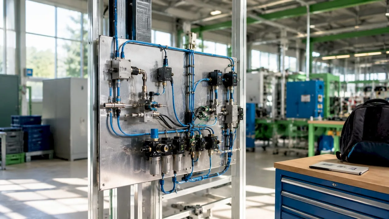
Real-time data visualization takes place via industrial SCADA systems or cloud dashboards. The technician sees current pressure, flow, and temperature on a single screen and can respond to anomalies immediately.
Digital twins and simulation accuracy
A digital twin of a pneumatic system is a virtual model that replicates the behavior of the physical equipment. The simulation must account for air compressibility and seal friction so that the results match reality with an accuracy of over 95%. This accuracy makes it possible to test configuration changes virtually before physical intervention. The result is a reduction in development and project integration time of up to 50%.

Professional tip: Before deploying a digital twin, measure the actual system parameters under various operating conditions. A simulation calibrated on real data achieves significantly higher accuracy than a model based solely on catalog values.
An overview of air pressure measurement options and the selection of the right sensors for intelligent systems can be found in a separate guide.
What are the benefits of IoT for energy savings and maintenance?
IoT technology is changing the way industrial companies approach energy efficiency and maintenance planning. The results are measurable and repeatable.
| Area of benefit | Result of IoT deployment | Mechanism |
|---|---|---|
| Energy consumption | Reduction of 25–35% | Precise control of pressure and flow according to current needs |
| Maintenance costs | Reduction of 30–50% | Transition from time-based to condition-based maintenance |
| System reliability | Increase of 40–60% | Early anomaly detection and predictive interventions |
| Project integration time | Reduction of up to 50% | Digital twins and thermodynamic simulations |
Traditional time-based maintenance operates on the principle of fixed intervals regardless of the actual condition of the equipment. The technician replaces a filter or seal after a specified number of operating hours have elapsed, even though the component is still functional. IoT replaces this approach with condition-based maintenance: intervention occurs when sensor data indicates actual wear.
"Transitioning to condition-based maintenance through IoT reduces maintenance costs by 30–50% and increases system reliability by 40–60%."
Predictive diagnostics goes even further. Algorithms analyze trends in the data and predict failures before they occur. For example, a gradual decrease in flow at constant pressure signals filter clogging or an emerging leak. The technician receives an alert with sufficient advance notice for a planned intervention outside peak production hours. The result is higher availability of the production line and lower costs for unplanned repairs.
The long-term ROI of deploying IIoT in pneumatics depends on proper calibration of alarm threshold values and on the quality of the data model. A system that generates too many false alarms loses the operator's trust. Conversely, a system with overly lenient thresholds will miss actual faults.
How to successfully integrate IoT into pneumatic systems?
Successful integration of IIoT into pneumatic systems requires a systematic approach. The most common mistakes arise from underestimating the compatibility of existing infrastructure and from incorrect selection of communication protocols.
-
Compatibility assessment is the first step. Check whether existing PLCs and control systems support industrial communication protocols. Older devices without IO-Link or OPC UA interfaces require protocol converters. Correct selection of converters shortens integration time and reduces maintenance costs.
-
Defining the use case before selecting technology. First determine what you want to measure and what decision you will make based on the data. Collecting data without a clear purpose does not bring value. Without the right context, IoT data is of little use for optimizing production processes.
-
IT/OT convergence and security. Connecting operational technology (OT) with information systems (IT) opens up new vectors for cyber threats. Network segmentation, communication encryption, and regular firmware updates are basic requirements, not optional extras.
-
Pilot project on a single line. Start with a single production node, verify functionality, and only then scale up. IIoT is a continuous process requiring data management and scalability from the start, not a one-off project.
-
Data management and data model. Raw data without context has no value. Each data point must be related to a specific machine, order, and operating state. Only then can the data be used to optimize processes.
-
Scaling plan. The system architecture must account for expansion from the start. Adding further sensors or production nodes must not require a complete redesign of the infrastructure.
Professional tip: When selecting a communication protocol, do not start from the technology, but from the latency and data volume requirements. For simple sensors at the machine level, IO-Link is sufficient. For integration with the enterprise ERP, choose OPC UA. Combining both protocols within a single architecture is common and functional.
The fundamentals of pneumatic automation and the principles of controlling pneumatic systems in production are described in detail in a separate guide.
Practical applications of IoT in industrial pneumatics
Intelligent pneumatic systems find application in specific operational scenarios, where direct connection of sensors with the control layer brings measurable results.
- Real-time monitoring of air consumption makes it possible to identify leaks and inefficient consumption at the level of individual machines. A flow sensor with local data storage detects nighttime consumption during idle production, which typically signals a leak in the piping.
- Predictive maintenance of actuators and valves works based on analysis of pressure and flow trends. The system alerts to seal or valve wear before a production line failure occurs.
- Synchronization of pneumatic movements with the production line is key in applications with precise timing, for example during assembly or packaging. The IoT layer ensures that the pneumatic actuator responds to a signal from the production system with minimal latency.
- Integration with MES and ERP systems connects data from pneumatic sensors with production planning. The production manager sees actual machine availability and can plan capacities more accurately.
- Remote diagnostics and device management allows a technician to check the system status without being physically present at the machine. This function reduces the cost of service visits and shortens the response time to faults.
The trend for 2026 is heading toward direct communication between sensors and intelligent control for synchronization with production and minimizing downtime. This architecture, referred to as smart pneumatics, eliminates intermediate layers and reduces latency to a minimum.
An overview of current trends in pneumatic tools and their impact on production efficiency is available in a separate article.
Key findings
IoT in pneumatic systems delivers proven energy savings, reduces maintenance costs, and increases reliability, provided the integration is built on the right data model and suitably chosen communication protocols.
| Point | Details |
|---|---|
| Energy savings | Deployment of IoT reduces the energy consumption of pneumatic systems by 25–35% thanks to precise pressure control. |
| Condition-based maintenance | The transition from time-based to condition-based maintenance reduces costs by 30–50% and increases reliability by 40–60%. |
| Protocol selection | IO-Link is used for simple applications, OPC UA for enterprise integrations with MES and ERP systems. |
| Data context | Raw data without a relationship to machine status and order has no value for process optimization. |
| Pilot approach | IIoT integration starts on a single line with a clear use-case and only then is scaled to the entire operation. |
Practical experience: what works and what doesn't
While working with pneumatic systems in industrial operations, I have repeatedly seen the same pattern. A company invests in sensors and communication infrastructure, starts collecting data, and after three months finds that nobody is using the data. The problem is not the technology. The problem is the absence of a data model and clear responsibility for interpreting the results.
The most successful implementations I have observed had one thing in common: they started with one specific question. For example: „Where in the piping are we losing compressed air overnight?" This question defined which sensors were needed, where to place them, and how to interpret the results. Only after answering the first question was the system expanded to predictive maintenance and integration with MES.
The second typical mistake is underestimating IT/OT convergence. Operations technicians and the IT department have different priorities and different vocabulary. Without coordination, security gaps or duplicate infrastructure arise. I recommend appointing a single project coordinator who understands both worlds.
The investment in IIoT pays off, but not automatically. It pays off when data is properly contextualized, protocols correctly chosen, and the team prepared for continuous system management. Pneumatics is a physical technology with precisely measurable parameters. IoT turns it into a system that learns and improves. That is real value, not a marketing promise.
— Zdeněk
Pneumatic components for IoT-ready systems
Quality physical infrastructure is a prerequisite for any successful IoT integration. Sensors measure accurately only when the piping is airtight, the air is properly treated, and the components are in good condition.
Kompresory-vzduchotechnika offers a range of components directly suitable for industrial IoT applications. Compressed air distribution tubing with push-in fittings ensures airtight and easily expandable piping, which is the foundation of reliable flow measurement. Air treatment units maintain the quality of compressed air at a level that protects sensors and actuators from premature wear. The Kompresory-vzduchotechnika team provides technical advice on selecting components for specific operating conditions and requirements for integration with IoT systems.
Frequently asked questions
What is IIoT and how does it differ from IoT in pneumatics?
IIoT (Industrial Internet of Things) is the industrial variant of IoT with higher scalability, reliability, and low latency. In pneumatics, it ensures safe real-time control that consumer IoT does not provide.
Which sensors are essential for monitoring pneumatic systems?
The basic set includes pressure, flow, and temperature sensors. Flow sensors with local data storage and transmission via MQTT or OPC UA cover most operational requirements.
Which communication protocol should be chosen for a pneumatic IoT system?
IO-Link is suitable for simple applications at the sensor level. OPC UA ensures interoperability when integrating with enterprise MES and ERP systems. The choice depends on the complexity of the architecture and the data flow requirements.
How quickly does the investment in IoT in pneumatics pay off?
The exact payback period depends on the scope of deployment and the initial state of the system. Condition-based maintenance reduces costs by 30–50 %, and energy savings reach 25–35 %, which typically ensures a payback period of under two years for medium-sized operations.
How to start integrating IoT into an existing pneumatic system?
Start with a pilot project on a single production line with a clearly defined use case. Verify the compatibility of existing control systems, choose a suitable communication protocol, and only scale to the entire operation once the results have been verified.
Recommended
- Pneumatic systems explained: a guide for technicians - Kompresory-Vzduchotechnika.cz
- What is pneumatic automation: a guide for industry - Kompresory-Vzduchotechnika.cz
- Why use pneumatics: efficiency, speed and safety - Kompresory-Vzduchotechnika.cz
- How to Safely Use Pneumatic Tools: A Guide - Kompresory-Vzduchotechnika.cz

The Importance of Air Leak Detection: A Guide for 2026
We have merged this article with a more detailed and more up-to-date guide on the same topic. Continue here: How to eliminate air leaks: a guide for a 42% energy saving.

Air Flow Testing Methods: A Guide for Technicians

Summary:
- Correct air flow measurement is crucial for system diagnostics and compliance with standards.
- Methods such as flow hoods and anemometers enable precise determination of volumetric flow, provided they are correctly positioned and calibrated.
Air flow measurement is defined as the quantification of the volume or mass of air passing through a duct cross-section or opening per unit of time. Correct air flow testing methods are the foundation of diagnostics for pneumatic systems, ventilation, and air conditioning. Standards such as LEED and BREEAM require measurement accuracy within ±10% of the measured value. This means that an error greater than 10% directly jeopardizes the certification of a building or industrial facility. The Czech technical standard ČSN EN sets similar requirements for industrial applications. Without validated measurement, it is not possible to reliably set the compressor output, fan, or control valve.
What are the main methods of air flow measurement?
Direct volumetric flow measurement using capture hoods, also known as balometers, is among the most reliable methods for ventilation systems. HVAC flow hoods cover a range of 25–4,000 m³/h with an accuracy of ±3%. This accuracy is sufficient for certification measurements under both LEED and BREEAM. Flow hoods with built-in pressure compensation also eliminate errors caused by uneven flow, which are typical for designer diffusers and grilles.
Anemometers form the second major group of measuring instruments. They are divided into vane anemometers and thermal anemometers according to the physical measurement principle.
- Vane anemometers measure air velocity in the range of 0.5–30 m/s with an accuracy of ±1.5% + 0.3 m/s. They are suitable for common duct measurements and chimney flues.
- Thermal anemometers are suitable for low velocities in the range of 0.01–2 m/s. Their high sensitivity is an advantage when measuring supply air in cleanrooms or laboratories.
- Pitot tubes operate on the principle of differential pressure according to Bernoulli's equation. They are inexpensive and durable, but require a uniform flow profile.
- Multi-point pressure probes allow velocity averaging across the entire duct cross-section. Technicians recommend them for online measurement in modern HVAC applications.
The choice of method depends on the velocity range and the nature of the flow. Thermal anemometers excel at low velocities, while vane anemometers are more robust for standard industrial ducting.
Professional tip: If you are measuring flow at a design diffuser or grille with an irregular shape, always use a hood with pressure compensation. Point measurement with an anemometer on such an element systematically gives distorted results.
How to correctly select and position the measuring instrument?
The selection of the measuring device is governed by three criteria: flow range, required accuracy, and type of application. For industrial pneumatic systems with higher flows and pressures, vane anemometers or Pitot tubes are suitable. For low-speed measurement in laboratories or clean rooms, a thermal anemometer is the correct choice.

Probe placement determines the quality of the result to the same extent as the type of instrument. Correct probe position is critical. A minimum distance from turbulent elements corresponding to several times the pipe diameter is recommended. Elbows, fans, constrictions, and T-pieces create turbulence that distorts the result. If a sufficient straight section is not available, multi-point measurement resolves the situation.
Selection and installation procedure:
- Determine the flow range and required accuracy according to the standard or project documentation.
- Choose the type of instrument corresponding to the velocity range and environment (temperature, humidity, dustiness).
- Identify the measuring point with a sufficient straight section both before and after the probe.
- In the case of an uneven flow profile, plan a multi-point measurement and calculate the average.
- Check the tightness of the probe connection and the airtightness of the hoses.
- Verify the validity of the instrument's calibration before starting the measurement.
Calibration is the foundation of the technical validity of every measurement. Standard calibration is performed in aerodynamic tunnels according to ISO 17025 at a minimum of 5 points across the range. For intensive professional use, a calibration frequency of approximately once a year is recommended.
- Keep calibration certificates for each instrument.
- If you have doubts about the result, perform a comparative measurement using two instruments.
- Calibrate damaged or contaminated probes immediately, not only at the scheduled date.
Professional tip: When installing airtight hoses for measuring small flow rates, always choose a hose inner diameter matching the nozzle of the measured device. An unsuitable diameter creates back pressure, which distorts the result for small pneumatic pumps and compressors.
How to perform airflow measurement step by step?
A correct measurement procedure ensures repeatability and comparability of results. Each step has its purpose, and omitting it will affect the quality of the data.
- Preparation of the measuring point. Check that the system is in a steady operating state. Verify that fans, compressors, and control valves are operating at the designed values.
- Instrument check. Verify the calibration validity, the condition of the probe, and the battery. For digital instruments, check the unit settings and temperature and pressure compensation factors.
- Probe placement. Insert the probe into the measuring point in accordance with the manufacturer's instructions. Maintain minimum distances from turbulent elements.
- Performing the measurement. For anemometers, allow the instrument to stabilize for at least 30 seconds before taking the reading. For hoods, place the edge tightly against the measured element and wait for the reading to settle.
- Multi-point measurement. For an uneven flow profile, measure the velocity at multiple points across the cross-section and calculate the average. Uneven flow forces technicians to use multi-point measurements and pressure compensation to achieve accuracy.
- Data recording. Record the measured values, including the temperature, pressure, and air humidity at the time of measurement. These parameters are necessary for converting to standard conditions.
- Verifying results. Repeat the measurement at least three times and compare the values. A deviation between repetitions greater than 5% indicates unstable conditions or a measurement error.
The basic formula for calculating flow is the product of cross-section and velocity. Real conditions, however, require compensation for current temperature and pressure, because air density changes with these variables. Without correction, the result may be misleading, especially when measuring during summer months or at altitudes above 500 m above sea level.
| Measurement method | Typical range | Accuracy | Suitable application |
|---|---|---|---|
| Flow hood (balometer) | 25–4,000 m³/h | ±3 % | Ventilation grilles, diffusers |
| Vane anemometer | 0.5–30 m/s | ±1.5% + 0.3 m/s | Pipes, chimneys |
| Thermal anemometer | 0.01–2 m/s | high sensitivity | Clean rooms, laboratories |
| Pitot tube | medium and high velocities | depends on calibration | Industrial pipelines |
| Multipoint pressure probe | wide range | depends on calibration | HVAC online monitoring |

What are the most common mistakes when testing air flow?
Incorrect probe placement is the most common cause of inaccurate results. A probe placed too close to an elbow, fan, or constriction picks up turbulent flow that does not represent the actual flow in the duct.
Other common mistakes include:
- Invalid instrument calibration. An instrument without a current calibration certificate produces results that cannot be technically justified. Calibration according to ISO 17025 is a prerequisite for measurement in certification projects.
- Unsuitable hose for measuring small flows. A hose with too small an internal diameter creates back pressure, which distorts the result for small pneumatic devices.
- Omitting temperature and pressure correction. Calculating flow without accounting for current conditions leads to a systematic error. The effect of variable pressure on measurement accuracy is well documented in industrial applications.
- Single-point measurement with an uneven profile. A single reading at the center of the duct does not capture the entire cross-section. The result can be tens of percent higher or lower than the actual average flow.
- Insufficient system stabilization. Measuring during fan start-up or shutdown captures a transient state, not the operating value.
Direct measurement of volumetric flow using fume hoods is essential for certification and verifying the proper function of ventilation and air conditioning in both construction and industry.
Eliminating these errors does not require expensive equipment. It requires a disciplined procedure, valid calibration, and knowledge of flow behavior in the specific system. Regular checking of air flows and archiving results make it possible to detect system degradation in time.
Key takeaways
The most reliable air flow measurement results come from a combination of a correctly chosen method, valid calibration, and multi-point measurement with an uneven flow profile.
| Point | Details |
|---|---|
| Method selection according to speed | Thermal anemometers for 0.01–2 m/s, vane anemometers for 0.5–30 m/s, hoods for ventilation elements. |
| Probe placement outside turbulence | Maintain the minimum distance from elbows and fans or use multi-point measurement. |
| Calibration according to ISO 17025 | Calibrate instruments at least once a year at a minimum of 5 points across the range. |
| Temperature and pressure correction | Supplement each flow measurement with current temperature and pressure values for conversion to standard conditions. |
| Archiving of results | Record all measurements, including conditions, for later comparison and system validation. |
Practical experience: what actually determines measurement accuracy
Over years of working with pneumatic systems, I've found that the biggest errors don't come from using the wrong instrument. They come from using the wrong procedure with a good instrument. A technician with a cheap but freshly calibrated vane anemometer and a correctly chosen measurement point will get a better result than a colleague with an expensive thermal instrument positioned 20 cm behind an elbow.
The second thing that surprised me in practice is underestimating the effect of temperature. I measured flow in a production hall in January and in July. Without temperature correction, the difference in the measured values would have looked like a system fault. In reality, it was just a difference in air density. Converting to standard conditions immediately eliminated this apparent problem.
A trend I've been observing in recent years is the deployment of multi-point pressure probes for continuous online flow monitoring in industrial HVAC systems. These probes do not require regular manual intervention and transmit data directly to control systems. Their disadvantage is the need for calibration to the specific pipe configuration, which increases initial costs. For large installations, however, this investment pays off quickly thanks to early detection of leaks and performance drops.
I recommend that every technician put together their own checklist for each type of measurement. A standardized procedure eliminates forgotten steps and makes it easier to compare results over time. Measurement accuracy is not a matter of talent. It's a matter of discipline and the right tools.
— Zdeněk
Pneumatic systems and flow measurement: what Kompresory-vzduchotechnika offers
Accurate air flow measurement starts with a correctly set up and maintained pneumatic system. Kompresory-vzduchotechnika offers technical advice for selecting measurement instruments, accessories, and components suitable for a specific application.
For stable and repeatable measurement results, quality air treatment units are essential, as they maintain constant pressure and cleanliness of air in the system. Kompresory-vzduchotechnika offers classic units for treating compressed air up to 10 bar as well as metal air treatment units up to 18 bar for more demanding industrial applications. Correctly sized and maintained components are a prerequisite for measurements whose results can be trusted.
Frequently Asked Questions
What are air flow testing methods?
Air flow testing methods are technical procedures for quantifying the volume or velocity of air in a pipe or opening. They include the use of fume hoods, anemometers, Pitot tubes, and multi-point pressure probes.
How to measure airflow in a pneumatic system?
Airflow is measured with an anemometer or a Pitot tube placed in a straight section of pipe outside turbulent zones. The result must be corrected for the current air temperature and pressure.
What measurement accuracy for airflow is required by standards?
LEED and BREEAM standards require measurement accuracy below ±10% of the measured value. HVAC fume hoods achieve an accuracy of ±3%, which meets this requirement with a margin.
How often should airflow measuring instruments be calibrated?
For intensive professional use, calibration approximately once a year is recommended in accordance with ISO 17025. Calibration is performed at a minimum of 5 points across the range in a wind tunnel.
Why is multi-point airflow measurement important?
An uneven flow profile means that a single-point measurement cannot capture the entire cross-section of the pipe. Multi-point measurement averages the velocities across the entire cross-section and gives a result corresponding to the actual flow.
Recommended
- Air pressure measurement options: a guide for technicians - Kompresory-Vzduchotechnika.cz
- A guide to industrial air distribution: operating efficiency - Kompresory-Vzduchotechnika.cz
- Why air purity is measured: methods and health - Kompresory-Vzduchotechnika.cz
- How to eliminate air leaks: a guide to a 42% energy saving - Kompresory-Vzduchotechnika.cz

Why monitor compressor vibrations: a guide for technicians
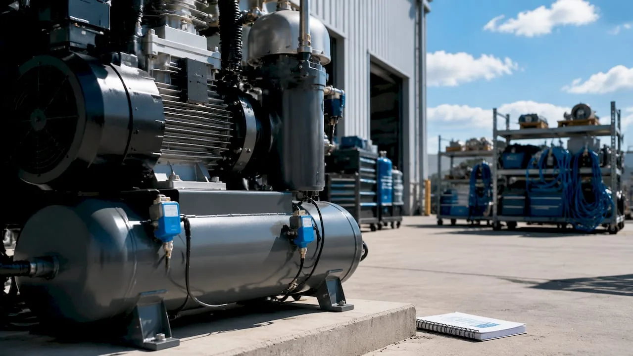
In brief:
- Regular monitoring of compressor vibrations enables early detection of technical faults and reduces repair costs. Vibration diagnostics identifies changes in the vibration profile that signal an impending component failure before it occurs. Modern sensors and automatic monitoring increase the reliability and efficiency of machine maintenance.
Compressor vibration monitoring is a fundamental diagnostic method for early detection of technical problems and ensuring efficient operation. In industrial practice, this method is referred to as vibration diagnostics. It is a non-disassembly method according to industrial standards, which allows faults to be localized without stopping production. Vibrations do not merely signal noise or shaking. Every change in the compressor's vibration profile reflects a specific technical condition of a component, bearing, or shaft. Technicians who regularly monitor vibrations move from reactive repair to planned maintenance, thereby reducing repair costs and unplanned downtime.
Why monitor compressor vibrations and what they tell us
Compressor vibrations are a direct reflection of its technical condition. Every component, from bearings through the shaft to the piston assembly, creates a characteristic vibration pattern during operation. If this pattern changes, it signals a specific problem even before a failure or breakdown occurs.
Every compressor component has a unique vibration signature, and monitoring it enables a transition to preventive maintenance that saves time and costs. In practice, this means the technician does not have to wait for visible signs of failure. A change in amplitude or frequency of vibration at a specific point on the machine precisely indicates which component is starting to fail.
Vibrations are divided into two basic types:
- Free vibration arises after a single impulse, for example at startup or impact. It dies out on its own without an external source of energy.
- Forced vibration is continuous and is caused by a repeating force, such as rotor imbalance, a worn bearing, or a loose joint.
Forced vibration is key for diagnostics. Its frequency corresponds to the machine's speed or multiples of the speed, so frequency analysis directly reveals the source of the problem. Rotor imbalance manifests at the fundamental rotational frequency, while a damaged bearing manifests at higher harmonic components. Compressors most often fail due to operation outside specifications, and vibrations signal this wear earlier than other methods.
Operating conditions and the surrounding environment have a direct impact on vibrations. Improper placement of the compressor on the floor, missing damping pads, or proximity to other machines can amplify vibrations and mask the actual condition of the equipment. Therefore, vibration data must always be evaluated in the context of the entire operating environment.

How to measure compressor vibrations: methods and technologies
Compressor vibration measurement is carried out in practice using accelerometers. These are sensors that detect vibration acceleration and convert it into an electrical signal. The result is a time waveform or frequency spectrum, from which a technician can read the condition of individual components.
Modern sensors enable real-time vibration measurement and remote monitoring, so that faults can be predicted before the machine has to be shut down. Remote monitoring is especially valuable for compressors in continuous operation or in hard-to-reach locations.
During measurement, we monitor two basic parameters:
- Vibration amplitude indicates the intensity of vibration. An increasing amplitude signals a deteriorating condition of the component.
- Vibration frequency determines which component is causing the problem. Frequency analysis (FFT, i.e. Fast Fourier Transform) decomposes the complex vibration signal into individual components.
In addition to accelerometers, vibration velocity sensors and non-contact shaft position sensors (eddy current probes) are also used. The choice of sensor depends on the type of compressor, the frequency range, and the required measurement accuracy.
Professional tip: Always place sensors as close as possible to the bearings. The longer the vibration transmission path, the more the signal becomes distorted, and the lower the diagnostic value of the data.
Real-time data collection is enabled by continuous monitoring systems. These systems record vibration values at regular intervals and automatically alert the operator when the set limits are exceeded. The advantage is that the technician sees the trend of vibration development over time, not just the instantaneous condition. The trend is more valuable for diagnostics than a single measurement.
Interpreting the measured values requires a reference baseline. When the compressor is commissioned, an initial vibration profile, the so-called vibration signature, is measured. All subsequent measurements are compared with this reference condition. A deviation by a predetermined value triggers an alarm or a planned inspection.
How vibration monitoring helps prevent failures
The shift from reactive to preventive maintenance is the main benefit of vibration diagnostics. The reactive approach means repairing the compressor only after a failure occurs. The preventive approach means intervening at the moment when vibrations indicate an approaching problem, and planning the repair without an unplanned shutdown.
The practical procedure for implementing preventive maintenance based on vibrations looks as follows:
- Measure the baseline vibration profile of a new or freshly repaired compressor. This profile serves as the reference point for all future measurements.
- Set alarm limits. Industry standards, such as ISO 10816, define permissible vibration values for different types of machines and power classes.
- Measure regularly and record trends. A single measurement has limited value. Only a series of measurements over time reveals whether the condition of the machine is deteriorating.
- Link vibration data with other parameters. Bearing temperature, oil pressure, and energy consumption complement the vibration picture with an overall view of the compressor's condition.
- Plan repairs based on data, not on a time schedule. A compressor with stable vibrations does not require premature bearing replacement. Conversely, a machine with increasing amplitude needs intervention sooner than the schedule prescribes.
Investment in systems that increase compressor efficiency pays back in 3 to 6 months under two-shift operation of up to 6,000 motor hours per year. Vibration diagnostics, as part of a preventive maintenance system, contributes to this return by reducing the costs of unplanned repairs and extending component lifespan.
Early detection of problems has a direct economic impact. Replacing a bearing at a scheduled time costs a fraction of the cost compared to a failure that damages the compressor shaft or housing. An unplanned shutdown also halts production, which further multiplies the costs. Compressors with an inverter reduce the number of start-stop cycles, thereby increasing operational stability and reducing the need for maintenance. Vibration diagnostics and the correct choice of compressor technology thus complement each other.
Proper compressor diagnostics includes vibration analysis as one of the key tools for maintaining efficient operation.
Common mistakes in vibration monitoring and how to avoid them
The most common mistake in vibration diagnostics is focusing only on symptoms instead of causes. Misinterpretation of vibrations leads to unnecessary replacement of functional components and unnecessary costs. A technician who sees increased vibrations on a bearing must first determine whether the cause is bearing wear or rotor imbalance transferring the load onto that particular bearing.
Other common mistakes include:
- Confusing vibration with noise. Noise is an acoustic manifestation of vibration, but its intensity does not correspond to the severity of the mechanical problem. A quiet compressor may have critical vibrations at frequencies outside the audible range.
- Measuring under unsuitable conditions. Vibrations from surrounding machinery, shocks from production, or unstable power supply distort the measured data. Measurements should be carried out under calm conditions without external interference to ensure the data is as accurate as possible.
- Monitoring only one parameter. Vibration amplitude without frequency analysis will not reveal which component is problematic. Conversely, a frequency spectrum without amplitude trend monitoring will not reveal whether the condition is worsening.
- Ignoring environmental and structural influences. Vibration diagnostics reveals not only the internal condition of the machine but also external influences on the structure and floor that affect the compressor's lifespan. Improper mounting or missing damping elements cause vibrations even in an otherwise flawlessly serviced machine.
- Absence of a reference measurement. Without a baseline vibration profile, it is not possible to assess whether the measured values are normal or alarming.
Professional tip: Always compare vibration data with bearing temperature and oil pressure. The combination of these three parameters gives a more reliable picture of the compressor's condition than any single parameter alone.
An overall view of the machine's condition is a prerequisite for correct diagnostics. Vibrations are one of the diagnostic tools, not the only one. Technicians who are familiar with the most common operating mistakes and actively prevent them achieve significantly lower failure rates for their compressors.
Key findings
Regular monitoring of compressor vibrations using the vibration diagnostics method is the most reliable way to prevent unplanned failures, reduce repair costs, and extend the service life of the equipment.
| Point | Details |
|---|---|
| Vibration signatures of components | Each component has a unique vibration profile, a change in which signals a specific fault. |
| Non-intrusive diagnostics | Vibration diagnostics reveals faults without stopping production, in accordance with industry standards. |
| Reference measurement as a baseline | The initial vibration profile at startup is essential for the correct evaluation of all subsequent measurements. |
| Data correlation for accuracy | Combine vibration data with bearing temperature and oil pressure for a reliable diagnosis. |
| Economic return | Preventive maintenance based on vibration reduces repair costs and shortens downtime. |
Vibration diagnostics in practice: what I've learned over the years with compressors
Zdeněk shares his perspective here.
Over the years of working with industrial compressors, I've found that the biggest mistake isn't a faulty sensor or bad software. The biggest mistake is stopping measurements the moment the compressor is "running fine". That's precisely when the reference baseline is built, without which all later measurements are just numbers without context.
Vibration diagnostics has saved production for me on several occasions. I specifically remember a case where frequency analysis showed a growing amplitude at a frequency corresponding to the bearing's outer race. The compressor operated normally, and the noise was the same as always. Without vibration measurement, we would have replaced the bearing only after a failure, likely with damage to the shaft.
I recommend that every company implement vibration monitoring as part of a standard operational protocol, not as a tool for crisis situations. Continuous monitoring systems with automatic alarms are now available even for medium-sized enterprises, and their acquisition costs are a fraction of the price of a single unplanned breakdown.
Modern technologies, such as wireless accelerometers and cloud platforms for data collection, significantly reduce the demands on personnel. A technician does not need to be physically present at every measurement. Data arrives automatically and the trend is evaluated continuously. This is exactly the shift from reactive to predictive maintenance that has been discussed in the industry for years, but which is only now becoming accessible to ordinary facilities.
— Zdeněk
Technical background for proper compressor operation
Vibration diagnostics is only one part of overall compressor care. Equally important is the correct compressed air distribution and quality air treatment before entering the pneumatic system.
Kompresory-vzduchotechnika offers a complete range for compressed air treatment, including filters, regulators, and automatic lubricators for proper operation of pneumatic systems. For more demanding applications, metal treatment units up to 18 bar are available. The Kompresory-vzduchotechnika team provides technical advice on equipment selection and on solving specific operational problems. A correctly designed and maintained compressed air system reduces vibrations transmitted to the piping and extends the service life of the entire installation.
Frequently Asked Questions
What is compressor vibration diagnostics?
Vibration diagnostics is a non-disassembly method of measuring and analyzing compressor vibrations during operation. It allows the localization of component failures, such as bearings or the rotor, without stopping production.
How often should compressor vibrations be measured?
The measurement frequency depends on the operating intensity and the criticality of the equipment. For compressors in continuous operation, continuous monitoring is recommended; for less utilized machines, monthly or quarterly measurements with trend comparison are recommended.
What sensors are used for vibration measurement?
The most common sensors are accelerometers, which measure vibration acceleration. For precise bearing diagnostics, they are supplemented with temperature sensors and, in some applications, non-contact shaft position probes.
How do you know when compressor vibrations are alarming?
Vibrations are alarming when their amplitude exceeds the reference value from the baseline measurement or the limits defined by ISO 10816. The trend is decisive: an increasing amplitude over time is always a warning sign.
Can vibration diagnostics reveal problems beyond the compressor itself?
Yes. Vibration diagnostics also reveals environmental influences, such as improper compressor positioning or missing damping pads, which cause vibrations even in an otherwise properly serviced machine.
Recommended
- Compressor bleeding procedure: a guide for technicians - Kompresory-Vzduchotechnika.cz
- Definition of the compressor duty cycle: a guide for technicians - Kompresory-Vzduchotechnika.cz
- The significance of the compression stage: a guide for technicians - Kompresory-Vzduchotechnika.cz
- Checklist of accessories for compressors: a guide for technicians - Kompresory-Vzduchotechnika.cz

Definition of Quality Air: Parameters, Standards and Measurement

In brief:
- Quality air has optimal concentrations of pollutants and physical parameters. For correct assessment, both outdoor and indoor environments are measured, including PM particles, CO2, humidity and temperature. Continuous monitoring of these parameters is key to protecting health and performance.
Quality air is air with optimal concentrations of pollutants and physical parameters that ensure a healthy and comfortable environment for people. The technical term for this area is air quality (in Czech kvalita ovzduší), whereby in practice both outdoor and indoor environments are assessed. Key parameters include dust particles PM10 and PM2.5, carbon dioxide (CO2), relative humidity and temperature. Czech legislation, specifically Act No. 201/2012 Coll. on air protection, sets binding limits for pollutants and forms the basis for assessment using the Air Quality Index (IKO). Proper understanding of these parameters is the first step towards protecting health and performance.
What is the definition of quality air and which parameters determine it?
Quality air meets precisely defined values of pollutant concentrations and physical quantities. It is not enough to monitor a single indicator. Only the combination of all parameters gives a complete picture of the condition of the environment.

Dust particles PM10 and PM2.5
PM10 are particles with a diameter of up to 10 micrometers, while PM2.5 are up to 2.5 micrometers. Smaller particles penetrate deeper into the respiratory tract and cause more serious health problems. The European Union sets the annual limit value for PM2.5 at 25 µg/m³ and for PM10 at 40 µg/m³. Exceeding these limits increases the risk of cardiac and pulmonary diseases.
Carbon dioxide as an indicator of ventilation
CO2 is the best indicator of indoor ventilation quality. Values above 1,000 ppm signal insufficient air exchange and lead to fatigue and reduced ability to concentrate. The optimal CO2 level in residential and working spaces lies below 1,000 ppm. Monitoring CO2 is therefore a basic tool for anyone who wants to maintain a healthy indoor environment.
Relative humidity and temperature
The optimal indoor humidity is 40–60%. When humidity drops below 30%, mucous membranes dry out and susceptibility to respiratory infections increases. Conversely, humidity above 60% promotes the growth of mold and dust mites. Air temperature is closely related to the feeling of thermal comfort and also affects the perception of humidity.

Monitoring all parameters together is essential. Air with a low concentration of PM2.5 but excessive humidity still represents a health risk.
Professional tip: Get a combined sensor that measures CO2, humidity, and temperature at once. Such devices are available from manufacturers such as Aranet or CO2Meter and provide a comprehensive overview of air condition in a single device.
What air quality standards and measurement methods apply in the Czech Republic?
The Czech Republic follows Act No. 201/2012 Coll. on Air Protection, which defines pollutants and sets their limit values. The act implements European directives and imposes obligations on both industrial facilities and state administration bodies.
Air Quality Index and its methodology
The new IKO methodology in the Czech Republic uses three-hour moving averages of PM10, NO2, and SO2 concentrations. This change brings a more accurate and realistic assessment of the current situation compared to the older daily averages. The IKO ranges on a scale from 1 to 7, with a lower number indicating better air quality. The results are publicly available through the Air Quality Information System.
Methods for measuring indoor air
Several technologies exist for measuring the indoor environment:
- CO2 sensors based on NDIR technology (non-dispersive infrared spectroscopy) are the most accurate method for measuring carbon dioxide indoors.
- Relative humidity sensors work on a capacitive or resistive principle and are part of most combined meters.
- Laser particle counters detect PM2.5 and PM10 in real time and are suitable for both industrial and home use.
- Electrochemical sensors measure concentrations of gases such as CO, NO2, or VOC (volatile organic compounds).
| Parameter | Measurement method | Recommended device |
|---|---|---|
| CO2 | NDIR sensor | Aranet4, CO2Meter |
| Humidity | Capacitive sensor | Combined meters |
| PM2.5 / PM10 | Laser particle counter | Industrial detectors |
| NO2, CO | Electrochemical sensor | Multi-purpose analyzers |
Professional tip: For industrial applications, choose measuring instruments certified according to EN 14211 or EN 14907. These standards guarantee measurement accuracy and comparability of results with reference methods used by state stations.
The state monitoring network in the Czech Republic is operated by the Czech Hydrometeorological Institute (ČHMÚ), which manages dozens of measuring stations throughout the country. Private companies and industrial enterprises acquire their own measuring systems for internal control. The choice of suitable equipment depends on the required accuracy, environment, and budget.
How to improve air quality indoors and outdoors?
Indoor air tends to be two to five times more polluted than outdoor air. The cause lies in emissions from cooking, cleaning, furniture, and building materials. Without regular ventilation and filtration, pollutants accumulate in enclosed spaces and worsen the health condition of occupants.
Ventilation as the basis
Short, intensive cross-ventilation for 3–5 minutes is more effective than long-term micro-ventilation. Cross-ventilation quickly exchanges the air throughout the entire room while also saving heating costs, since the walls do not have time to cool down. Ventilation is the cheapest and most accessible method of improving air quality in the household.
Air filtration and cleaning technologies
Air purifiers with HEPA filters reduce illness rates by capturing dust particles, allergens, and bacteria. The World Health Organization (WHO) links indoor air pollution to millions of premature deaths per year. Besides HEPA filters, there are activated carbon filters for capturing volatile organic compounds and UV lamps for destroying microorganisms.
Reducing sources of pollution
The main sources of indoor pollution include:
- Smoking indoors, which produces PM2.5 and hundreds of toxic substances.
- Chemical cleaning agents with a high VOC content, which are released into the air during use.
- Dust mites and mold in carpets, upholstery, and damp areas, which produce allergens.
- Printers and copiers in offices, which emit ozone and fine toner particles.
- New furniture and flooring made of chipboard or laminates, which release formaldehyde.
Professional tip: When choosing an air purifier, pay attention to the CADR (Clean Air Delivery Rate) value. This value indicates the volume of cleaned air per hour and allows you to compare the performance of different devices regardless of the manufacturer's marketing descriptions.
Humidity control and outdoor air
Proper air humidity strengthens immunity and reduces the risk of respiratory illness. Humidifiers are suitable in winter, when heating reduces humidity below 30%. Dehumidifiers, on the other hand, help during the summer months or in basement areas. Outdoor air quality depends on traffic, industry, and meteorological conditions, with temperature inversions and calm wind having the greatest impact.
Comparison of methods for ensuring healthy air
Choosing the right method depends on the specific environment, requirements, and available budget. Different air filtration technologies vary in efficiency, operating costs, and maintenance requirements.
| Method | Advantages | Disadvantages | Suitable environment |
|---|---|---|---|
| Window ventilation | Zero cost, simple | Dependent on outdoor air, heat losses | Households, offices |
| Controlled ventilation with heat recovery | Energy savings, constant air exchange | High acquisition costs, installation required | New buildings, industry |
| HEPA filtration | High efficiency for particles | Does not remove gases, filter replacement required | Allergy sufferers, hospitals, laboratories |
| Activated carbon filter | Captures VOCs and odours | Low efficiency on particles | Offices, production halls |
| Combined system | Comprehensive protection | Higher cost and complexity | Industry, healthcare |
Window ventilation is sufficient for ordinary households with low outdoor air pollution. Industrial facilities and healthcare establishments require a combination of controlled ventilation and multi-stage filtration. EU and Czech legislation sets strict limits for SO2, NO2, PM10 and CO, with regions exceeding these limits required to develop plans to achieve the limit values. The choice of technology therefore always starts with an analysis of the specific environment and the applicable standards.
Key findings
Air quality is a system of interrelated parameters that requires continuous monitoring and a combination of ventilation, filtration and limitation of pollution sources.
| Point | Details |
|---|---|
| Definition of good-quality air | Air meeting the limit values for PM2.5, PM10, CO2 and humidity for a healthy environment. |
| Key parameters | CO2 below 1,000 ppm, humidity 40–60%, PM2.5 below 25 µg/m³ are the basic metrics. |
| Legislative framework | Act No. 201/2012 Coll. and IKO form the binding basis for assessing air quality in the Czech Republic. |
| Most efficient ventilation | Short intensive drafts of 3–5 minutes are more effective than continuous micro-ventilation. |
| Technology selection | Combining ventilation and HEPA filtration provides the best protection in both industrial and residential environments. |
Air quality in practice: what actually works
I have been working with air quality issues in industrial and residential environments for a long time, and one thing still surprises me. Most people only address air quality once health problems or unpleasant odours appear. Yet prevention costs a fraction of the expense of dealing with the consequences.
The most common mistake I see is relying on a single method. Some people buy an air purifier and stop ventilating. Others ventilate regularly but ignore humidity, which drops to 20% in winter. Both situations lead to a deterioration in the quality of the environment, just for different reasons.
The second thing that is often underestimated in practice is measuring air cleanliness. Without data, you don't know whether your measures are working. A CO2 sensor costing a few hundred crowns will immediately show you whether ventilation is sufficient. This is information you cannot otherwise obtain.
I recommend starting with measurement, and only then investing in technology. You will find out what is actually missing, and you won't buy unnecessary devices. Air quality is not a one-off project. It is ongoing care, just like the maintenance of any technical system.
— Zdeněk
Air quality solutions from Kompresory-vzduchotechnika
Kompresory-vzduchotechnika offers technical solutions for industrial and operational air treatment, from filters and pressure regulators to complete compressed air treatment systems. The product range includes components for industrial filtration and accessories for precise air quality control in demanding operations.
For industrial applications, systems are available that meet the ISO 8573 standard, which defines compressed air purity classes. Kompresory-vzduchotechnika's technical support will help you select the right solution according to the specific environment and requirements. The entire range of pneumatic components is available online, with the option of expert consultation.
Frequently asked questions
What does quality air mean according to Czech legislation?
Quality air meets the limit values for pollutants set by Act No. 201/2012 Coll. on air protection. Evaluation is carried out using the Air Quality Index (IKO), which is based on moving averages of PM10, NO2 and SO2 concentrations.
What is the optimal CO2 concentration indoors?
The CO2 concentration should be below 1,000 ppm. Higher values indicate insufficient ventilation and cause fatigue and reduced ability to concentrate.
How to measure air quality at home?
The most accessible method is a combined sensor measuring CO2, humidity and temperature. Laser particle counters, which are also available for home use, are used to detect PM2.5 dust particles.
What humidity level is healthy?
Relative humidity of 40–60% is optimal for a healthy indoor environment. Humidity below 30% dries out mucous membranes, while humidity above 60% promotes the growth of mold and mites.
Why is indoor air often more polluted than outdoor air?
Indoor air tends to be two to five times more polluted than outdoor air due to emissions from cooking, cleaning products, furniture and building materials. Without regular ventilation and filtration, pollutants accumulate in enclosed spaces.
Recommended
- Why air purity is measured: methods and health - Kompresory-Vzduchotechnika.cz
- Why monitor air humidity: a guide to a healthy home - Kompresory-Vzduchotechnika.cz
- Compressed air treatment units up to 18 bar
- Air pressure measurement options: a guide for technicians - Kompresory-Vzduchotechnika.cz

What is industrial ventilation: a guide for manufacturing facilities

In short:
- Industrial ventilation ensures controlled air exchange in production halls and protects workers' health. The system includes fans, filters, ducting, and control elements, with proper sizing being key to efficiency. The correct selection of the fan, filter maintenance, or proper ducting design is often underestimated, which reduces system performance.
Industrial ventilation is defined as controlled air exchange in production and industrial spaces, aiming to supply fresh air and remove air contaminated with dust, chemical substances, or heat. The technical term for this field is industrial air handling. The system consists of fans, filtration units, duct distribution, and control elements. Properly designed industrial ventilation protects workers' health, meets occupational health and safety requirements, and maintains stable conditions for production processes. Without functional ventilation, contaminants accumulate in the halls, temperature rises, and productivity decreases.
What is industrial ventilation and how does it work as a system?
Industrial air handling is a set of technologies ensuring controlled air exchange in demanding production conditions. It provides fresh air supply, removal of contaminated air, and stable conditions even under high dust levels, the presence of chemical substances, or thermal load.
The basic principle is straightforward. The fan creates negative pressure, which draws air from the source of contamination through the duct distribution into the filtration units and out of the hall. This controlled air movement is the key principle of industrial ventilation. Without properly designed airflow, air does not follow the path from the source of contamination to the exhaust, and contaminants spread throughout the space.
The system consists of several interconnected parts. Each part performs a specific function, and the failure of one reduces the performance of the entire system:
- Fans ensure the movement of air and overcome the resistance of ducting and filters.
- Duct distribution carries air from the extraction points to filtration and exhaust.
- Filtration units capture solid particles, aerosols, or gaseous substances.
- Control elements (dampers, valves) allow control of flow in different branches of the system.
- Supplementary separators such as cyclones serve as pre-filtration before fine filters.
Professional tip: Place extraction points as close as possible to the source of contamination. The shorter the distance between the source of dust or fumes and the inlet of the extraction ducting, the lower the airflow needed to capture the contaminants, and the smaller the fan you will need.
The efficiency of industrial ventilation depends on a comprehensive assessment of the entire system, not just individual components. A powerful fan combined with improperly sized ducting or a clogged filter will not deliver the expected results.
What is the difference between an axial and a radial fan?
Choosing the right fan is one of the most important decisions when designing industrial ventilation. Axial and radial fans differ in construction, performance, and suitable application.
An axial fan moves air parallel to the axis of rotation. It handles large airflows at low system resistance. Typical applications include ventilating large production halls, warehouses, or supplying fresh air to spaces without long ducting runs. A radial fan (centrifugal) moves air by centrifugal force perpendicular to the axis of rotation. It generates higher pressure and overcomes the resistance of long ducting runs and filtration units.
| Parameter | Axial fan | Radial fan |
|---|---|---|
| Airflow | High | Medium to high |
| Static pressure | Low | High |
| Typical use | Hall ventilation, air supply | Extraction with filtration, long ductwork |
| Noise level | Lower | Higher |
| Energy consumption | Lower at low resistance | Higher, but efficient under resistance |
Fan static pressure is a key parameter that affects the actual air flow in an installed system with ductwork and filters. Manufacturers state the flow rate in m³/h at zero resistance. In a real system with piping, dampers and filters, the actual flow rate is always lower.
Fan selection must take into account not only the flow rate but, above all, the static pressure of the system and the resistance of the filtering elements. Underestimating this parameter leads to undersizing of the entire system.
Professional tip: Before selecting a fan, always calculate the total resistance of the system. Add up the losses in the ductwork, dampers, grilles and filters. Only then select a fan whose operating point lies on its performance curve at the required flow rate.
Industrial fans for specific applications, such as switchboard cooling, use a specific power supply and output expressed as air flow in m³/h. Each application requires a different type and sizing of equipment.
What types of filters are used in industrial ventilation?
Filtration is an integral part of every industrial ventilation system. Industrial fluid power uses cyclones, fabric filters, electrostatic precipitators, and adsorption filters in demanding operations. The choice of filtration depends on the type and composition of the contaminants.
Proper filtration of industrial air directly affects employee health and the safety of production facilities. Insufficient filtration causes occupational diseases and shortens machine service life.
Overview of the main types of filters and their use:
- Cyclones capture heavier solid particles by centrifugal force without consuming filter media. They serve as the first stage of pre-filtration before fine filters.
- Fabric (textile) filters capture fine dust with high efficiency. They are used in the woodworking industry, metal grinding, or in the food industry.
- Cartridge filters offer a large filtration area in a compact design. Suitable for continuous operation with automatic cleaning using compressed air.
- Electrostatic precipitators capture aerosols, oil mists, and fine particles using an electrostatic charge. Typical use is in machining centers and paint shops.
- Adsorption filters (with activated carbon or zeolite) remove gaseous substances, solvent vapors, and odors. Essential wherever fabric filters are not sufficient.
| Filter type | Captures | Typical operation |
|---|---|---|
| Cyclone | Coarse solid particles | Woodworking industry, agriculture |
| Fabric filter | Fine dust | Grinding, wood, food industry |
| Cartridge filter | Fine dust, continuous operation | Welding, metals, ceramics |
| Electrostatic precipitator | Aerosols, oil mists | Machining, painting |
| Adsorption filter | Gaseous substances, vapors | Chemical industry, paint shops |
Multi-stage separation using cyclones and specialized filters significantly increases the reliability and service life of industrial ventilation systems. The cyclone captures heavier particles and reduces the load on fine filters, thereby extending the intervals between filter cartridge replacements.
A detailed overview of types of air filtration systems for manufacturing will help in selecting the right combination for a specific operation.
How to design industrial ventilation for a production hall?
The design of industrial ventilation begins with calculating the required air volume. This calculation depends on the type of work, the number of workers, the type of contamination, and the heat load of the space. Without a correct calculation, the result is either an undersized system that fails to perform its function, or an oversized system with unnecessarily high operating costs.
Procedure for designing a ventilation system for a production hall:
- Identify the sources of contamination. Map all locations where dust, vapors, heat, or noise are generated. Each source requires its own extraction point or at least needs to be accounted for in the total airflow.
- Calculate the required airflow. The air exchange at the workplace must correspond to the type of work. For work without dust and chemicals, the standard of 25 m³/h per employee applies. For higher heat loads or odor, this amount is increased by 10 m³/h per person.
- Design the duct routes. Ductwork systems carry the air from the extraction points to filtration and exhaust. Unsuitable bends and dampers add hydraulic losses and reduce the efficiency of the entire system. Design the routes to be as direct as possible with a minimum of elbows.
- Select filtration according to the type of contamination. The filter type must correspond to the substances being captured. For dust, a textile or cartridge filter is sufficient, for aerosols an electrostatic precipitator is necessary, and for vapours an adsorption filter.
- Size the fan according to the total system resistance. Add up the losses in the ductwork, filters, and other components. Select a fan with an operating point corresponding to the required flow rate at this resistance.
- Take temperature and humidity into account. High temperature or humidity changes the air density and thus the actual fan performance. These parameters affect both the choice of fan and the material of the ductwork and filters.
Professional tip: When designing ductwork, allow for an air velocity in the ducts ranging from 5–10 m/s for main branches and 3–6 m/s for sub-branches. Higher velocities increase noise and hydraulic losses, while lower velocities cause dust to settle in the ductwork.
Properly sized air ductwork systems are the foundation of efficient air distribution in large industrial facilities. The duct diameter directly determines the flow velocity and thus the hydraulic losses of the entire system.
Workers' thermal comfort is part of occupational health and safety and affects productivity. An overheated or poorly ventilated hall increases error rates and sickness absence. Ventilation must ensure not only the removal of contaminants but also the maintenance of acceptable temperature and humidity at the workplace.
Key findings
Industrial ventilation functions as a system of interconnected components, where the performance of the whole depends on the correct sizing of each part, from the fan through the ductwork to the filtration.
| Point | Details |
|---|---|
| System definition | Industrial ventilation is a controlled air exchange ensuring the supply of fresh air and the removal of contaminated air in production premises. |
| Fan selection | Axial fans are used for large spaces with low resistance, radial fans for systems with filtration and long ductwork. |
| Multi-stage filtration | A cyclone as pre-filtration extends the service life of fine filters and reduces their maintenance requirements. |
| Airflow sizing | The standard specifies a minimum of 25 m³/h per employee for dust-free work, with an additional 10 m³/h per person added for thermal load. |
| Duct systems | Unsuitable bends and dampers increase hydraulic losses and reduce the actual airflow in the system. |
Practical experience: what is most often underestimated in industrial ventilation
The biggest mistake I see in practice is fan undersizing. The designer or operator selects a fan based on the airflow stated in the catalogue at zero resistance. However, a real system with ductwork, filters and dampers always has resistance. The result is a fan that delivers only a third of the promised airflow, and the hall remains full of dust or fumes.
The second most common mistake is neglected maintenance. Filter cartridges gradually become clogged and reduce airflow. Regular inspection of filter condition and timely replacement are essential for maintaining ventilation performance and equipment service life. I have seen facilities where the filter was not replaced for two years. The fan was running at full capacity, but hardly any air was passing through the clogged filter.
The third problem is the approach of "I'll buy one big fan and solve everything". Industrial ventilation works as a system. One powerful fan without properly designed extraction points, ductwork and filtration will not help. Contaminants must be captured directly at the source, not after they have already dispersed throughout the entire hall.
I recommend that every production hall operator carry out a ventilation system inspection once a year. Check the condition of the filters, measure the actual air flow at the extraction points and compare it with the design values. A deviation greater than 20% indicates a problem that needs to be addressed before it affects workers' health or production quality.
— Zdeněk
Industrial ventilation from Kompresory-vzduchotechnika
Kompresory-vzduchotechnika offers technical consulting and supplies of components for industrial ventilation systems. The product range includes fans, filtration units, ducting accessories and control elements for production facilities of various sizes.
The expert team at Kompresory-vzduchotechnika will help you select the right equipment according to the specific parameters of your operation, the type of contamination and the required air flow. Technical support includes consultation during system design as well as service after installation. The entire range of pneumatics, ventilation equipment and accessories can be found in the industrial pneumatics and hydraulics section on the Kompresory-vzduchotechnika website.
Frequently Asked Questions
What is industrial ventilation and what is it for?
Industrial ventilation is a system for controlled air exchange in production spaces. It ensures the supply of fresh air, the removal of contaminated air, and maintains safe working conditions for employees.
What is the difference between an axial and a radial fan?
An axial fan moves a large volume of air at low system resistance and is suitable for ventilating halls. A radial fan generates higher pressure and overcomes the resistance of filters and long ducting runs.
How often should filters in industrial ventilation be changed?
The replacement interval depends on the intensity of operation and the type of contamination. The condition of the filters needs to be checked regularly, as clogged filters reduce air flow and put a strain on the fan.
How much air does one worker need in a production hall?
The standard specifies a minimum of 25 m³/h per employee when working without dust and chemicals. At higher heat loads or odour levels, this amount increases by 10 m³/h per person.
What is an industrial fan and how does it differ from a domestic one?
An industrial fan is designed for continuous operation, high airflow rates, and overcoming the resistance of ducting and filters. A domestic fan operates at low resistance and short-term operation, without requirements for filtration or dust resistance.
Recommended
- The importance of multi-way valves in industrial systems - Kompresory-Vzduchotechnika.cz
- How air valves work: their key role and efficient solutions - Kompresory-Vzduchotechnika.cz
- Why use safety valves in industry and construction - Kompresory-Vzduchotechnika.cz
- Safety valves: Function, selection and the right capacity - Kompresory-Vzduchotechnika.cz

What is a blow gun: a guide for technicians

In brief:
- A blow valve controls the flow and pressure of compressed air in pneumatic systems.
- A distinction is made between hand-held guns and automated valves controlled by an electrical signal.
A blow valve is a device for controlling the flow, pressure and direction of compressed air in pneumatic systems. The term covers two distinct categories: hand-held blow guns for manual cleaning and drying, and automated valves controlled by an electrical signal for precise industrial applications. In professional practice, the term solenoid valve or directional valve is used for the automated variants. The correct choice between these types directly affects the efficiency of the entire pneumatic circuit, air consumption and operational safety.
What is a blow valve and how does it work?

A blow valve controls when and where compressed air flows in a pneumatic circuit. Hand-held blow guns work on a simple principle: pulling the trigger opens the flow of air through the nozzle. Automated solenoid valves receive electrical signals from a PLC and switch the flow with high precision and repeatability. This ability to precisely dose air is essential in automated production lines, where manual operation is not sufficient.
The basic technical parameter of every valve is the number of ports and positions, written as X/Y. The number before the slash indicates the number of connections (ports), and the number after the slash indicates the number of working positions. The most common configurations are:
- 3/2-way valve: three ports, two positions. Used for simple switching of the air supply to a single consumer, for example a pneumatic cylinder with single-acting movement.
- 5/2-way valve: five ports, two positions. The standard choice for double-acting pneumatic cylinders, where both forward and backward movement must be controlled.
- 5/3-way valve: five ports, three positions. Additionally offers a neutral position, which defines the behavior of the actuator in the event of a signal or power failure.
Hand-held blow guns operate at a pressure of around 6 bar and consume 110–300 l/min of air depending on the nozzle used and the set pressure. This consumption is significantly higher than that of automated valves, where the flow is controlled precisely according to process requirements.
Professional tip: When designing a pneumatic circuit, always specify the required flow rate in l/min at a specific working pressure. Underestimating the flow rate leads to a pressure drop at the point of use and a loss of performance of the entire system.
What are the most common causes of blow-off valve failures?
Blow-off valve failures generally have four main causes: mechanical wear of seals, contaminants in the air, incorrect installation, and incorrect selection of the neutral position for 5/3-way valves. Each of these causes manifests differently and requires a different approach to prevention.
The most common procedure for diagnosing failures:
- Check the quality of the compressed air. Moisture, oil, and solid particles destroy valve seals. A filter and condensate separator upstream of the valve are a necessity, not an optional accessory.
- Verify the valve orientation during installation. Incorrect orientation leads to functional failures. Vertical installation is a condition for correct operation in many valves and prevents unwanted leaks.
- Check the seals and O-rings. Mechanical wear of seals manifests as air leakage audible as hissing or a drop in circuit pressure.
- Assess the choice of neutral position for 5/3-way valves. An incorrect neutral position causes uncontrolled actuator movement during a power failure, which is a safety risk.
- Perform a regular functional test. The valve should switch smoothly without sticking. Increased switching force or a delayed response indicates wear or contamination.
The neutral position of a 5/3-way valve is a critical parameter for safety. A closed center locks the actuator in place during a power failure. An exhaust center releases pressure from both sides of the cylinder and allows free movement. A pressure center keeps the actuator pressurized on both sides. Confusing these variants when designing a circuit causes dangerous machine behavior.
Professional tip: Every time you replace a valve, check the condition of the filter and condensate separator. Contaminated air is the most common cause of premature failure of a new valve.
Manual gun vs. automated valve: a comparison of types
The choice between a manual and automated solution depends on the application, the required precision, and the method of operation. The following table summarizes the key differences:
| Parameter | Manual blow gun | Solenoid valve |
|---|---|---|
| Control | Manual, by operator | Electrical signal, PLC |
| Working pressure | Up to 6.2 bar | Typically 2–10 bar |
| Air consumption | 110–300 l/min | Controlled according to the process |
| Dosing accuracy | Low | High, repeatable |
| Typical use | Cleaning, drying, servicing | Automation, production |
| Configuration | Simple (1-way) | 3/2, 5/2, 5/3 |
| Safety features | Air strainer | Neutral position selection |
Manual guns, such as the SAM models with a working pressure of 6.2 bar and a safety air strainer, are suitable for service workshops, car repair shops, and workshops. Solenoid valves are essential wherever pneumatic actuator movement needs to be controlled automatically, without an operator present.
Advantages of solenoid valves in automation:
- Precise and repeatable switching independent of the operator
- Integration into PLC control systems and industrial automation
- Possibility of remote control and diagnostics
- Choice of neutral position for safe behaviour in case of power failure
- Lower air consumption thanks to controlled flow
Guns with a long nozzle allow cleaning of narrow and hard-to-reach places at pressures up to 6 bar. This variant is standard in the automotive industry and engineering workshops, where cavities and channels need to be cleaned without disassembly.
How to select and correctly integrate a blow gun valve?
Correct valve selection begins with defining the application. The technician must know three basic parameters: the required working pressure, the required air flow, and the method of control. Only based on these values can the correct type and configuration be chosen.
Criteria for valve selection:
- Working pressure: The valve must handle the maximum pressure in the system with a reserve. Operating at the limit of the nominal pressure shortens the lifespan of the seals.
- Flow rate (Kv value): Too small a flow coefficient causes a pressure drop. An oversized valve unnecessarily increases costs and can cause surges in the circuit.
- Port and position configuration: For simple switching, 3/2 is sufficient, for bidirectional actuators 5/2, for applications requiring defined behavior during power loss 5/3.
- Neutral position for 5/3 valves: The choice of neutral position affects operational safety and energy consumption. This decision must be part of the circuit design, not an afterthought.
- Medium and air quality: Valves for lubricated air cannot be used in systems without lubrication and vice versa. The manufacturer's specification is binding.
- Mounting position: A series of valves requires a specific orientation for proper function. Horizontal mounting where the manufacturer specifies vertical leads to failures.
Technical consultation is key when selecting a valve for non-standard applications. The balance between tightness, flow resistance, control, and cost is not always evident from catalog sheets. An experienced technician or supplier can identify hidden design risks before they manifest as a failure in operation.
Valve installation must respect the flow direction marked on the body. Swapping the inlet and outlet ports causes malfunction or damage to the valve. After installation, a functional test at operating pressure must be performed and the tightness of all connections checked.
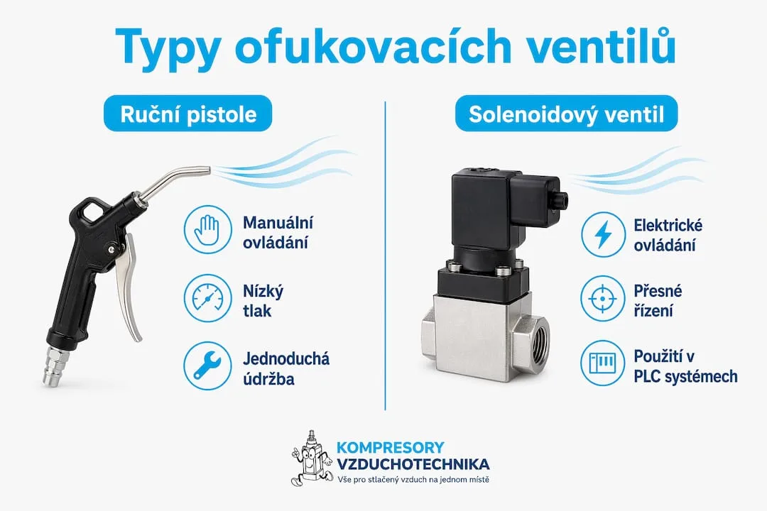
Professional tip: When integrating a solenoid valve into a PLC system, always verify the coil supply voltage and the output type of the control system. Swapping the voltage or using an incorrect output module causes immediate damage to the coil.
The efficiency of a pneumatic system depends on the entire chain of components, from the compressor through the air receiver and air treatment to valves and actuators. The valve is only one link. An undersized piping system or insufficient air treatment will devalue even a correctly selected valve.
Key findings
A blow valve operates reliably only when it matches the application, is correctly installed, and is supplied with clean air at the appropriate pressure.
| Point | Details |
|---|---|
| Definition and types | A blow gun includes both manual guns and solenoid valves; the choice depends on the application and the required precision. |
| 3/2, 5/2, 5/3 configurations | The number of ports and positions determines the valve's function in the circuit; 5/3 additionally defines behaviour in the event of a power failure. |
| Neutral position | An incorrect choice of neutral position in a 5/3 valve causes safety risks and uncontrolled actuator movement. |
| Air quality | Moisture and contaminants are the main cause of premature valve failure; a filter upstream of the valve is a necessity. |
| Selection and consultation | Correct valve selection requires knowledge of pressure, flow and application; technical consultation reduces the risk of an incorrect choice. |
Practical experience: what technicians overlook
Zdeněk, pneumatic systems technician
Over the years of working with pneumatic circuits, I've found that the biggest problems are not caused by faulty valves, but by poor decisions made during design. The most frequently overlooked parameter is the neutral position of a 5/3-way valve. Technicians select it based on what they have in stock, not on what the application requires. The result is an actuator that either moves uncontrollably in the event of a power failure or, conversely, remains locked in a position where it should release pressure.
The second recurring problem is air quality. I have seen installations where a new valve failed within three months because there was no filter installed upstream. The valve's datasheet specifies requirements for media cleanliness, but hardly anyone reads them before installation. Yet a filter with a condensate separator costs a fraction of the valve's price and extends its service life several times over.
I recommend that every technician start the circuit design process from the end: what should happen in the event of a power failure? This question determines the choice of neutral position, and thus the type of valve. Only then does it make sense to address flow, pressure, and the method of installation. Approaching it in the opposite direction leads to a redesign or, in the worst case, to a failure on the production line.
Multi-way valves are a standard in industry, but their correct function in systems depends on details that are not listed in catalogues. Consulting with a supplier before purchase is an investment, not a waste of time.
— Zdeněk
Blow Guns and Pneumatic Accessories at Kompresory-vzduchotechnika
Kompresory-vzduchotechnika offers a complete range of products for pneumatic systems, from blow guns and solenoid valves to piping, air treatment, and compressors. Technicians will find products here for service workshops as well as for industrial automation, including technical support in selecting the right solution.
For manual applications, blow guns and spray guns for working with compressed air are available. Pneumatic piping can be supplemented with compressed air tubing of the push-in system in diameters of 15–28 mm. Air treatment upstream of valves is ensured by air treatment units for classic applications up to 10 bar. The Kompresory-vzduchotechnika team provides technical advice on selecting valves, components, and complete pneumatic assemblies.
Frequently Asked Questions
What is a blow valve in pneumatics?
A blow valve is a device for controlling the flow, pressure, and direction of compressed air. This includes manual blow guns as well as automated solenoid valves for industrial applications.
How does a solenoid blow valve work?
The solenoid valve receives an electrical signal from the PLC and mechanically switches the air flow between the ports. It enables precise and repeatable air dosing without manual operation.
What is the difference between a 5/2-way valve and a 5/3-way valve?
A 5/2-way valve has two working positions and is used for bidirectional actuators. A 5/3-way valve adds a neutral position, which defines the actuator's behavior in case of power or signal failure.
What are the most common causes of blow-off valve failures?
The main causes are contaminated air with moisture and solid particles, seal wear, incorrect installation orientation, and incorrect selection of the neutral position on 5/3 valves.
Where to buy a blow valve for industrial use?
Blow valves and complete pneumatic accessories are offered by Kompresory-vzduchotechnika, a specialized supplier with technical support for selecting the right solution for a specific application.
Recommended
- The importance of multi-way valves in industrial systems - Kompresory-Vzduchotechnika.cz
- What is an isolation valve and how to use it correctly - Kompresory-Vzduchotechnika.cz
- The check valve in compressors: technical function and application - Kompresory-Vzduchotechnika.cz
- Why use safety valves in industry and construction - Kompresory-Vzduchotechnika.cz

The Role of Lubrication in Pneumatics: A Guide for Technicians
We have merged this article with a more detailed and more up-to-date guide on the same topic. Continue here: How to choose the right oil for a compressor: a guide 2026.

The meaning of the compression ratio: a guide for technicians
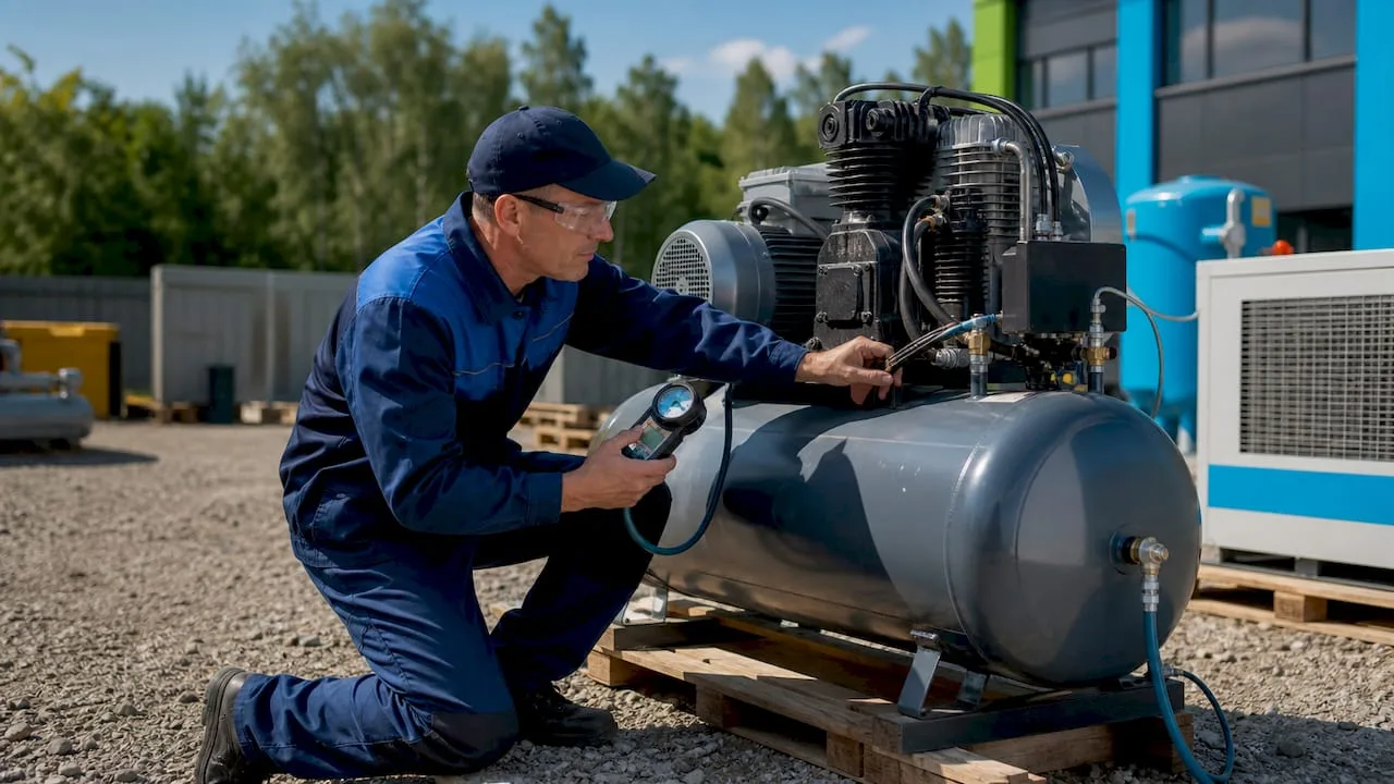
In brief:
- The compression stage is the fundamental functionality of a compressor, which determines the pressure-efficient compression of air. Proper configuration and regular maintenance extend service life and increase the efficiency of the entire system. The choice between a simpler and a multi-stage solution depends on the required pressure and operating conditions.
A compression stage is defined as one functional unit of a compressor, in which air passes through one compression cycle from a lower pressure to a higher pressure. This parameter determines how efficiently the equipment compresses air, what output pressure it achieves, and how long it will run without failures. For technicians and professionals in the compressed air field, understanding the compression stage is the basis for proper selection, operation, and maintenance of the entire system. Single-stage and multi-stage configurations differ in performance, energy consumption, and suitability for specific industrial applications.
How does a compression stage work and what is its structural significance?
A compression stage operates on the principle of reducing the volume of air in the working space, which increases its pressure. In piston compressors, the piston compresses air in the cylinder during its movement, valves control the air intake and outlet, and each cycle corresponds to one compression stage. Screw compressors use rotating screw rotors, which gradually compress air along the axis of the machine.
The structural arrangement of stages directly affects the force load on the crankshaft, vibrations, and power drop. The W-shaped configuration in three-stage piston compressors minimizes torsional vibrations and extends bearing life. Technicians who underestimate this relationship face premature failures and higher repair costs.
Basic types of piston compressor arrangements:
- Inline arrangement: simple, suitable for single-stage machines with lower pressure
- V-configuration: two cylinders at an angle, better force balance than the inline arrangement
- W-configuration: three cylinders, significantly lower vibrations, typical for multi-stage industrial compressors
- Radial arrangement: multiple cylinders evenly distributed around the crankshaft, maximum balance
Each arrangement affects bearing life, noise level, and the frequency of service interventions. Proper stage configuration reduces vibrations and torsional oscillations, which directly extends the service life of the equipment and saves maintenance costs.
Professional tip: When selecting a compressor for continuous operation, always check the cylinder configuration. W-configuration or radial (star) arrangement are significantly more reliable for 24-hour operation than a simple in-line design.
The working principle of a piston compressor is described in more detail in the technical analysis of piston compressors, where you will also find the effect of configuration on operation and maintenance.
What is the compression ratio and why does it determine performance?
The compression ratio is a number expressing the ratio of the working chamber volume before compression to the volume after compression. In internal combustion engines it is referred to as the engine compression ratio and directly determines the thermodynamic efficiency of the entire cycle. The same logic applies to industrial compressors: a higher ratio means greater compression of air in a single stage.
A higher compression ratio brings higher energy efficiency and performance, but requires control of fuel sensitivity to autoignition and material properties. For compressors, this means higher thermal load on components and the need for quality cooling. Without sufficient cooling, the temperature of the compressed air rises to levels that damage seals, lubricant, and the cylinders themselves.
Strict compression ratio regulations in motorsport show how critical precise monitoring and control of the compression ratio is for achieving optimal performance without exceeding specified limits.
A practical example comes from motorsport. From 1 June 2026, FIA will measure engine compression ratios when heated to 130 °C to prevent illegal increases in compression above the 16:1 limit. This measure was introduced because the difference in compression ratio between a cold and operating engine can be significant and affects energy utilization. Industrial technicians should learn a lesson from this approach: measuring the compression ratio only when cold is not enough.
| Parameter | Low compression ratio | High compression ratio |
|---|---|---|
| Output pressure | Lower | Higher |
| Energy efficiency | Lower | Higher |
| Thermal load | Lower | Higher |
| Cooling requirements | Minimal | High |
| Risk of self-ignition | Low | Higher |
| Suitability | Light-duty applications | Industrial operation |
Single-stage vs. multi-stage compressors: what determines the choice?
Choosing between a single-stage and multi-stage compressor depends on the required pressure, air volume and operating profile. Each type has clearly defined strengths and limitations.
Single-stage compressors
A single-stage compressor compresses air in a single step directly to the outlet pressure. Single-stage compressors achieve a pressure range of 100–150 psi and are suitable for light to medium-duty applications. Typical uses include auto repair shops, workshops, construction work and pneumatic tools with lower air consumption.

The advantage of single-stage machines is simple design, lower purchase price and easy maintenance. The disadvantage is higher compressed air temperature and lower energy efficiency at higher pressures.
Multi-stage compressors
A multi-stage compressor divides compression into two or more steps with intercooling between stages. Intercooling reduces the air temperature between stages, increases air density and thus improves the efficiency of the entire compression process. The outlet pressure of multi-stage machines exceeds 200 psi, which is necessary for industrial applications, painting, manufacturing or the food industry.
Intercooling is not just about reducing temperature. The higher air density after cooling allows the next stage to operate with lower energy loss. Regular intercooler maintenance is therefore essential for stable long-term operation.
- Check the intercooler at every scheduled maintenance. Fouling reduces efficiency and increases outlet temperature.
- Monitor the pressure difference between stages. A deviation from the manufacturer's specification indicates wear on valves or piston rings.
- Measure the outlet air temperature from each stage separately. Uneven values reveal a problem before it causes a failure.
- Replace air filters based on operating hours, not just the calendar. A dusty environment significantly shortens filter life.
| Compressor type | Pressure range | Typical use | Maintenance costs |
|---|---|---|---|
| Single-stage | 100–150 psi | Workshop, auto repair shop, construction | Low |
| Two-stage | 150–200 psi | Industry, paint shop, manufacturing | Medium |
| Multi-stage (3+) | above 200 psi | Heavy industry, special applications | Higher |
Professional tip: A two-stage compressor with intercooling consumes less energy for the same output than a single-stage machine operating at the limit of its pressure range. If your operation requires continuous pressure above 10 bar, a two-stage solution will pay back in energy savings within two years.

For a detailed comparison and the advantages of two-stage machines, see the article on the efficiency of two-stage compressors.
Practical applications and recommendations for technicians in operation
Choosing the correct compression stage for a specific application prevents most operational problems. A technician who knows the requirements of their operation will select the right machine and set it up to work within the optimal range.
The most common mistakes in selection and operation:
- Underestimating the required pressure: a compressor operating continuously at the upper limit of its range wears out faster and consumes more energy
- Ignoring the duty cycle: a machine designed for intermittent operation fails prematurely when run continuously
- Neglecting cooling: insufficient cooling of the compressor space increases intake temperature and reduces efficiency
- Incorrect lubricant choice: unsuitable lubricant carbonizes at high temperatures and fouls the valves
- Overlooking cylinder configuration: choosing a single-stage machine where a multi-stage one is needed leads to overloading and shortened service life
Selecting the right compressor for industrial use involves more parameters than just pressure and flow. Factors for selecting an industrial compressor include the operating profile, network quality, air purity requirements, and the maintenance plan.
Setting the compression stage correctly delivers measurable results. It reduces energy consumption, extends intervals between service interventions, and increases the reliability of compressed air supply. Technicians who regularly check the pressure parameters and temperatures of individual stages detect wear before it causes an unplanned shutdown. Tips for saving energy with a compressor show how correctly setting the compression stage directly affects operating costs.
Key takeaways
A correctly selected and set compression stage is the foundation for energy-efficient, reliable, and long-term sustainable operation of every compressor system.
| Point | Details |
|---|---|
| Definition of a compression stage | A single functional unit of the compressor providing one cycle of compressing air from a lower to a higher pressure. |
| Impact of configuration on service life | W-configuration and radial (star) arrangement minimize vibrations and extend bearing service life. |
| Compression ratio and performance | A higher compression ratio increases efficiency but requires good cooling and control of thermal load. |
| Benefit of intercooling | Intercooling in multi-stage compressors increases air density and reduces energy losses. |
| Maintenance as prevention | Regular inspection of the intercooler, valves, and pressure differentials between stages prevents unplanned shutdowns. |
Compression stage in practice: what I've learned over years in the field
Technicians most often make mistakes when selecting a compressor based on catalog pressure and flow rate, overlooking the stage configuration. I've seen workshops where a single-stage machine was permanently running at 10 bar because "that's how it's always been." The result was overheated valves, reduced lubricant lifespan, and service intervention every three months instead of once a year.
The second thing that surprised me in practice is the underestimation of intercooling. Technicians only clean the intercooler when the compressor starts overheating. Properly, the intercooler should be part of every scheduled inspection, because fouling of just 20% significantly reduces the efficiency of the entire second stage.
The future of compression systems is moving toward integrated sensors that monitor the pressure and temperature of each stage in real time. Machines with this feature enable predictive maintenance and eliminate unplanned shutdowns. For technicians, this means that knowledge of the compression stage is no longer just mechanical, but also data-driven.
I recommend every technician: learn to read your compressor's pressure diagram. A deviation from the normal pattern between stages is the first sign of a problem, long before it manifests as a failure.
— Zdeněk
Technical solutions for compression systems from Kompresory-vzduchotechnika
Kompresory-vzduchotechnika offers technical equipment for professionals who need reliable tools for operating and maintaining compression systems. The range includes pneumatic and hydraulic components suitable for both single-stage and multi-stage applications.
For technicians working with compressed air, the Professional KIT of blow guns for compressed air is available, containing tools for the everyday operation of compression systems. Additional pneumatic and hydraulic components cover the needs of industrial operations, from basic maintenance to demanding applications. The Kompresory-vzduchotechnika team provides technical support in selecting the right equipment for a specific compression system.
Frequently Asked Questions
What is a compression stage in a compressor?
A compression stage is one functional unit of a compressor in which air goes through one cycle of compression from a lower to a higher pressure. Each stage operates with its own valves, piston or rotor, and cooling system.
What is the difference between a single-stage and a two-stage compressor?
A single-stage compressor compresses air in one step to a pressure of 100–150 psi, while a two-stage compressor divides the compression into two steps with intercooling and reaches a pressure above 200 psi. A two-stage machine is more energy-efficient at higher pressures.
Why is intercooling important in multi-stage compressors?
Intercooling reduces the air temperature between stages and increases its density, allowing the next stage to operate with lower energy loss. A neglected intercooler reduces compression efficiency and shortens the service life of components.
How does the compression ratio affect compressor performance?
A higher compression ratio increases energy efficiency and discharge pressure, but at the same time increases the thermal load on components. Without sufficient cooling, damage occurs to seals, lubricant, and cylinders.
How can you tell that a compression stage needs servicing?
A signal is a deviation of the pressure differential between stages from the values stated by the manufacturer, increased discharge air temperature, or unusual vibrations. Regular monitoring of these parameters allows wear to be detected before it causes a failure.
Recommended
- Definition of the compressor duty cycle: a guide for technicians - Kompresory-Vzduchotechnika.cz
- Checklist of accessories for compressors: a guide for technicians - Kompresory-Vzduchotechnika.cz
- Compressor bleeding procedure: a guide for technicians - Kompresory-Vzduchotechnika.cz
- The role of lubrication in a compressor: a guide for technicians - Kompresory-Vzduchotechnika.cz

What Pneumatic Safety Means in Industry

In brief:
- Proper pneumatic safety combines fast emergency valves, SIL circuits and physical interlocking, which significantly reduces the risk of serious injuries. Key elements are emergency valves with a response time of up to 50 ms, monitoring of their status and robust interlocking mechanisms, which must not be confused with one another. Also important is the analysis of common cause failures and compliance with standards, in order to ensure real protection of workers.
Pneumatic safety is defined as a set of technical measures and systems designed to prevent accidents and protect workers during the operation of pneumatic equipment in industry. It includes three key components: emergency shut-off valves with a response time of 15–50 ms, safety circuits with a SIL level and dual-pressure interlocking preventing accidental release of pressure. Properly implemented pneumatic safety systems reduce the risk of serious injuries by 96–99%. For technicians and managers in manufacturing, this means a clear framework: without these elements, it is impossible to meet legislative requirements or to ensure real protection of operators.
What does pneumatic safety mean and how do its key components work?
Pneumatic safety is built on three functional layers: rapid circuit shut-off, physical pressure interlocking and controlled system status monitoring. Each layer performs a different function and they complement one another.

Emergency shut-off valves
Emergency shut-off valves must close the pneumatic circuit within 15–50 ms. This speed is crucial: human reaction time is approximately 200 ms, so the valve must act before the operator even registers the danger. Standard designs use dual solenoids with dynamic coil position monitoring. This arrangement ensures automatic diagnostics and fault tolerance within safety circuits with a SIL level.
Valve status monitoring is not an optional add-on. Without continuous feedback on the spool position, it cannot be confirmed that the valve has actually closed the circuit after an emergency stop activation. A correct safety circuit design therefore includes redundant position sensors and automatic test cycles.
Pneumatic interlocking versus a safety switch
These two elements perform fundamentally different functions, yet in practice technicians often confuse them. Pneumatic interlocking forms a physical barrier against accidental release of pressure. It mechanically isolates the energy source and prevents the system from restarting without a deliberate intervention by the operator.

A safety switch, on the other hand, controls system operation in start/stop mode. It does not physically prevent accidental release of pressure, so it cannot be used as a substitute for interlocking during servicing work or when entering a hazardous zone. Both elements are necessary and complement one another.
The role of safety circuits with a SIL level
Safety circuits with a SIL (Safety Integrity Level) rating determine how reliably a system will perform its safety function when a stop is required. A higher SIL level means a lower probability of failure on demand (PFDavg). Redundancy in the circuit, meaning the duplication of valves or sensors, directly increases the achieved SIL level. Without a correctly designed circuit, there is no guarantee that the safety function will operate exactly when it is most needed.
Professional tip: When designing a safety circuit, always verify whether the valve manufacturer provides certified PFDavg and B10d values. Without this data, SIL level validation cannot be performed.
How does pneumatic safety reduce risks in manufacturing operations?
A comprehensive approach to pneumatic system safety reduces the risk of serious injury by 96–99%. This figure applies to systems combining fast-acting valves, SIL circuits, and properly sized interlocks. A single emergency valve without redundancy and monitoring will not achieve such a result.
Valve response speed directly affects the extent of injury. A valve responding within 50 ms shuts off the circuit before the moving part of the machine comes into contact with the operator. A valve with a response time of 200 ms or more does not provide this protection. Correct sizing therefore includes calculating the stopping time of the entire motion system, not just the valve itself.
Safety measures in pneumatics also directly affect operational reliability. A system with automatic diagnostics detects valve degradation before it causes an unplanned production stoppage. A preventive approach thus reduces the costs of unplanned downtime while keeping safety functions operational.
The legislative framework in the Czech Republic and the EU requires machine manufacturers to demonstrate compliance with standards such as EN ISO 13849 or EN 62061. These standards directly reference performance levels (PL) and SIL levels that safety circuits must meet. Failure to comply with these requirements means not only legal liability but also higher insurance premiums and the risk of production shutdown during inspection.
Professional tip: When assessing compliance with EN ISO 13849, be sure to include the entire safety chain: the sensor, the logic, and the actuator. A fault in any one link will reduce the overall performance level of the system.
What hazards do pneumatic systems present and how can they be prevented?
Pneumatic systems involve four main categories of risk: uncontrolled air exhaust, residual pressure after shutdown, energy release, and mechanical failures caused by contamination.
Hazards of uncontrolled exhaust
Exhaust air can cause mechanical injuries, hearing damage, and component failure. Noise from direct exhaust exceeds 100 dB, while cumulative exposure above 85 dB damages hearing with prolonged exposure. The kinetic energy of particles carried by air at a speed of 100 m/s is sufficient to penetrate skin or damage the eye.
Exhaust velocities above 30 m/s in accessible locations are considered hazardous. ISO 4414 therefore recommends flow regulation as a standard measure. Noise mufflers, flow regulators, and special exhaust piping are specific technical solutions that eliminate this risk.
Overview of main hazards and protective measures
| Type of hazard | Cause | Protective measure |
|---|---|---|
| Exhaust noise | Direct exhaust above 85 dB | Noise muffler, exhaust piping |
| Kinetic energy of particles | Air velocity above 30 m/s | Flow regulator, exhaust guard |
| Accumulated pressure | Residual energy after shutdown | Lockout, vent valve |
| Air contamination | Dirt, moisture, oil | Filtration, regular filter replacement |
Safe system shutdown procedure
- Close the compressed air supply using the main shut-off valve.
- Activate the lockout on the energy supply.
- Vent the system through the vent valve or manual exhaust with a silencer.
- Verify with a pressure gauge that the pressure throughout the circuit has dropped to zero.
- Only then enter the hazardous zone or begin service work.
Accumulated pressure in pneumatic cylinders or reservoirs persists even after the supply has been shut off. This fact is the cause of many occupational injuries during service work. Venting must include all branches of the circuit, not just the main supply.
Regular maintenance and testing of safety devices are a prerequisite for maintaining functionality. Testing intervals are determined based on the PFDavg value and the required SIL level. Automatic diagnostics built into modern valves simplify this process but do not replace periodic physical verification.
How to select and implement pneumatic safety measures?
The selection of safety components begins with risk assessment. Without a formal risk assessment according to EN ISO 12100, it is not possible to determine what SIL level or performance level PL the safety function must meet. Risk assessment is therefore an input condition, not a formality.
Selection of interlocking devices according to ČSN EN 1088
The choice of interlocking devices must be based on risk assessment, compatibility with the machine's control system, and the requirements of the ČSN EN 1088 standard. A key mistake in practice is that the interlocking device is added as a supplement, rather than as an integrated safety part of the control system. This mistake reduces the overall achieved SIL level.
Comparison of types of interlocking devices
| Device type | Function | Suitable application |
|---|---|---|
| Mechanical interlocking | Physical isolation of the pressure source | Service work, entry into the zone |
| Electropneumatic interlocking | Controlled shut-off with confirmation | Automated lines, SIL 2–3 |
| Safety switch | Start/stop control | Operational control, not isolation |
| Emergency shut-off valve | Rapid circuit stop | Protection upon hazard detection |
Recommended implementation steps
- Carry out a risk assessment according to EN ISO 12100 and determine the required PL or SIL level for each safety function.
- Select valves with manufacturer-certified PFDavg and B10d values.
- Verify compatibility of locking devices with the machine's control system before purchase.
- Design a redundant circuit with status monitoring for SIL 2 and higher functions.
- Document the installation and perform a validation test before commissioning.
- Determine periodic testing intervals based on the required PFDavg value.
Standard ČSN EN 1088 defines principles for the design and selection of interlocking devices for protective guards. Its practical benefit lies in providing specific criteria for selection: type of actuator, locking method, and monitoring requirements. A technician who knows this standard can justify the choice of a specific device during an audit or when communicating with an insurance company.
During installation of a pneumatic system, safety elements must be installed before the first start-up, not added afterward. Subsequent installation increases costs and often compromises the achievable SIL level due to wiring limitations.
Insufficient consideration of common cause failures (CCF) can reduce the system's safety level several times over. CCF includes pressure fluctuations, air contamination, or adverse environmental conditions that can cause multiple redundant elements to fail simultaneously. Proper design therefore includes CCF analysis as part of the safety circuit validation.
Key findings
Pneumatic safety requires a combination of fast emergency valves, SIL circuits, and physical locking, with proper implementation reducing the risk of serious injuries by 96–99%.
| Point | Details |
|---|---|
| Valve response time | Emergency valves must close the circuit within 15–50 ms for the protection to be effective. |
| Interlocking vs. switch | Interlocking physically isolates pressure; a switch controls operation. They cannot replace each other. |
| CCF analysis | Common cause failures can invalidate redundancy; CCF analysis is mandatory. |
| Standard ČSN EN 1088 | Defines the criteria for selecting interlocking devices; risk assessment is a prerequisite. |
| Exhaust air | Velocities above 30 m/s and noise above 85 dB require silencers and flow regulators. |
A practical view: where pneumatic safety most often fails
I have worked with pneumatic systems for a number of years, and I repeatedly see the same pattern: a company meets the minimum legislative requirements, obtains a declaration of conformity, and considers the matter closed. The problem is that minimum compliance and actual safety are two different things.
The most common mistake I see is the absence of CCF analysis. Technicians install redundant valves and assume this achieves SIL 2. However, if both valves share the same air supply with fluctuating pressure or are exposed to the same contamination, the redundancy is illusory. A single common factor can cause both elements to fail simultaneously.
The second recurring mistake is confusing a safety switch with a lockout. I have seen operations where a technician merely turned off the switch before entering a hazardous zone. A switch can be turned back on accidentally or deliberately. A lockout cannot. This confusion has cost lives in the past.
I recommend that every production manager perform an internal audit of safety functions once a year. Not a paper audit, but physical verification: activate the emergency stop and measure the response time. Check whether lockout devices are actually in use during servicing. Training technicians in the safe use of pneumatic tools is an investment that pays off sooner than you think.
Comprehensive safety solutions in high-risk applications should not be built merely on minimal regulatory compliance. Combining multiple technologies significantly increases both safety and operational reliability. This is not theory, this is practice.
— Zdeněk
Safe pneumatic systems from Kompresory-vzduchotechnika
Kompresory-vzduchotechnika offers both technical support and a product range for building safe pneumatic systems in manufacturing. From compressed air treatment units through piping systems to screw compressors for industrial applications, all with an emphasis on reliable operation and compliance with safety standards.
Technicians and managers dealing with the implementation of safety measures or the selection of components for a specific application can take advantage of expert consultations directly on the website. Kompresory-vzduchotechnika provides technical support in selecting compressors, piping systems and accessories for safe and efficient pneumatic operation. The range of SCR screw compressors covers industrial applications with high demands on reliability and continuity of compressed air supply.
Frequently Asked Questions
What does pneumatic safety mean in industry?
Pneumatic safety is a set of technical measures protecting workers from the risks of pneumatic systems, particularly uncontrolled pressure release, exhaust air, and mechanical movements. It includes emergency valves, lockouts, SIL safety circuits, and regular testing.
What is the difference between a pneumatic lockout and a safety switch?
A pneumatic lockout physically isolates the pressure source and prevents restart without a deliberate intervention. A safety switch only controls start/stop operation and does not provide physical protection during servicing work.
How quickly must an emergency shut-off valve react?
The emergency shut-off valve must shut off the pneumatic circuit within 15–50 ms. This reaction time is shorter than human reaction time, ensuring protection before the operator registers the hazard.
What standards govern pneumatic safety measures?
The key standards are EN ISO 13849 and EN 62061 for safety functions of control systems, ČSN EN 1088 for interlocking devices, and ISO 4414 for general requirements for pneumatic systems. Risk assessment according to EN ISO 12100 is a prerequisite for selecting the correct measures.
Why is CCF analysis important for pneumatic safety systems?
Common cause failures (CCF) can cause multiple redundant elements to fail simultaneously, for example due to pressure fluctuations or air contamination. Without CCF analysis, a seemingly redundant system may fail as a whole and fail to achieve the declared SIL level.
Recommended
- How pneumatics works: a complete guide for industry 2026
- Why use pneumatics: efficiency, speed and safety - Kompresory-Vzduchotechnika.cz
- What is pneumatic lubrication: a guide for technicians - Kompresory-Vzduchotechnika.cz
- Pneumatic tools in 2025: trends and innovations - Kompresory-Vzduchotechnika.cz

Why monitor air humidity: a guide to a healthy home
This article is no longer up to date. Please go to the home page or look into our advice centre.

Why air purity is measured: methods and health
This article is no longer up to date. Please go to the home page or look into our advice centre.
Procedure for assembling an air distribution system: an installation guide
We have merged this article with a more detailed and more up-to-date guide on the same topic. Continue here: A guide to industrial air distribution: efficiency of operation.
Checklist for compressor accessories: a guide for technicians
We have merged this article with a more detailed and up-to-date guide on the same topic. Continue here: What to look for when buying a compressor: a checklist for workshops and companies.

Basic Requirements for a Compressor Room: 2026 Guide

Summary:
- Correctly designing a compressor room depends on detailed determination of flow and pressure according to actual consumption.
- Also important are structural and spatial requirements, such as floor load capacity and controlled ventilation, which protect the equipment from overheating and vibration.
Basic requirements for a compressor room are a set of technical, structural and operational criteria that must be met for safe and economical operation of a compressor system in an industrial environment. A correctly designed compressor room ensures a stable supply of compressed air, minimizes energy losses and extends the service life of the equipment. This guide covers key areas from flow and pressure sizing through structural standards to the control of multi-compressor systems. It is based on Atlas Copco recommendations and IEC 61511 standards, so you will get an overview that you can directly apply when designing or modernizing a compressor room.
1. Basic requirements for a compressor room: flow and pressure as the starting point
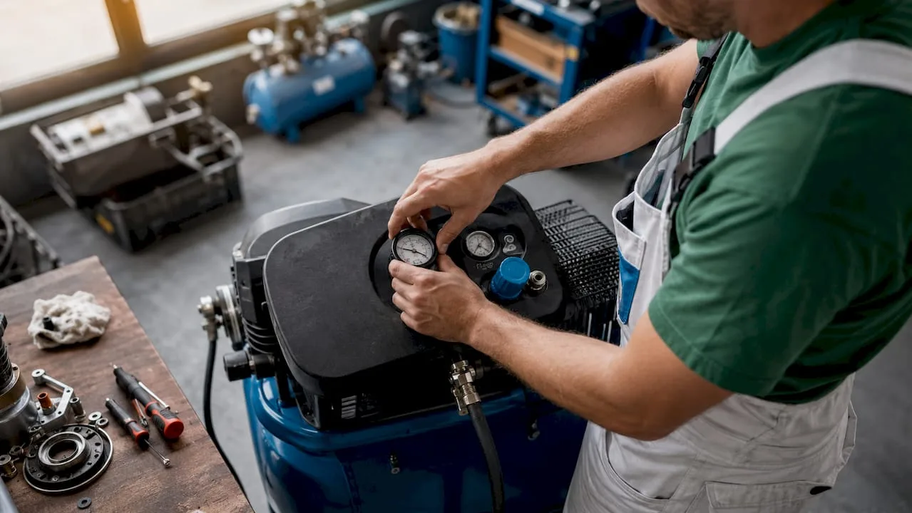
Correct design of a compressor room always starts with air flow (CFM) and working pressure (PSI or bar). These two parameters determine what compressor output is actually needed, and only from them is the power input in kW or HP derived. The opposite approach, i.e. selecting a compressor based on power without knowing actual consumption, leads to undersizing or oversizing of the system.
Atlas Copco recommends compiling a detailed list of all tools and applications with their CFM and PSI requirements. This list must include simultaneous operation of equipment, i.e. how many tools will be working at the same time and what their peak demand is.
Key steps in compiling technical requirements:
- List all points of use with their rated flow and pressure.
- Determine the simultaneity coefficient (not all equipment runs at the same time).
- Add a 10–20% reserve for future expansion.
- Include pressure losses in piping, filters and dryers.
Pressure losses are the most commonly underestimated factor. Atlas Copco points out that losses in dryers and filters can be significant enough that a compressor with a catalog-correct pressure fails to deliver the required pressure at the point of use. In practice, this means that if you need 6 bar at the point of use, the compressor must operate at 7 or 7.5 bar to cover the system losses.
Professional tip: When sizing, always start from the CFM and PSI requirements, and only then select the compressor power. This approach minimizes energy losses and prevents unnecessary oversizing.
Compressor power in kW is a supplementary parameter, not a starting point. Practical examples of compressor applications show that the same input power can correspond to very different flow rates depending on the compressor type and its efficiency.
2. Structural and spatial requirements for the compressor room
The compressor room space must meet specific structural and physical conditions. Having a free room is not enough. Flooring, ventilation, insulation, and vibration solutions are just as important as the selection of the compressor itself.
Floor load capacity and insulation
Industrial compressors are heavy equipment. For industrial compressors in containers, the floor is standardly reinforced to a load capacity of at least 1,000 kg/m². This value also applies as a default minimum for permanent compressor rooms in production halls. Insufficient floor load capacity causes vibrations that accelerate wear on joints and piping.
Insulation must meet fire resistance class A1 and include a 0.2 mm vapor barrier against condensation. Condensation in the structure of the compressor room causes corrosion of the structural elements as well as the equipment itself and shortens its service life.
Ventilation and cooling
| Parameter | Minimum requirement | Recommended value |
|---|---|---|
| Fresh air supply | Natural ventilation | Forced ventilation with louvres |
| Warm air exhaust | Opening near the ceiling | Fan with thermostat |
| Room temperature | Max. 40 °C | 20–30 °C |
| Air humidity | Max. 85% RH | Below 60% RH |
Compressors produce a large amount of waste heat. Without sufficient ventilation, the temperature in the compressor room quickly rises above the equipment's operating limits, triggering thermal protection and causing unplanned shutdowns.
Vibrations and noise
Compressors generate vibrations that are transmitted into the building structure and piping. Anti-vibration pads under the compressor are a basic measure. For larger installations, flexible joints at the compressor outlet and acoustic wall cladding are used. Noise in the compressor room commonly reaches 70–85 dB, so the space must be separated from workplaces with a requirement for lower noise levels.
Professional tip: Modular containerized compressor rooms from manufacturers such as CubeCont address load capacity, insulation, and ventilation as a whole. When expanding production, they save both time and costs, since the entire station can be relocated without construction work.
3. control of multi-compressor systems: lead and lag mode
Multi-compressor systems require a properly configured control system. Without it, compressors operate uncoordinated, wear unevenly, and consume more energy than necessary.
The principle of lead-lag control mode is that one compressor (lead) covers the base load and the other (lag) starts only when the lead compressor's capacity is exceeded. This arrangement extends the service life of both machines and reduces energy costs.
Typical setting parameters
| Parameter | Typical value |
|---|---|
| Lag compressor start delay | 30–60 s |
| Lag compressor stop delay | 60–120 s |
| Control pressure | 80–100 psig (5.5–6.9 bar) |
| Deadband | 10–20 psig (0.7–1.4 bar) |
Typical lead-lag mode settings specify a start delay of 30–60 s and a stop delay of 60–120 s. These delays prevent short cycling, which causes excessive wear on starting mechanisms.
Incorrect parameter settings lead to frequent compressor switching, increased wear, and higher energy consumption. Too narrow a deadband causes compressors to start and stop at short intervals, which is the most common cause of premature electric motor failure.
Safety shutdown
Safety features such as shutdown on high oil temperature, motor overload, or overpressure are mandatory under IEC 61511 and OSHA 1910.169 standards. These protections must be wired outside the PLC, i.e. directly in hardware, so that they function even in the event of control system failure.
Professional tip: Consult the compressor manufacturer or a service technician regarding deadband settings. Too wide a deadband causes pressure fluctuations in the network, too narrow a deadband wears out the compressors. The correct value depends on the air receiver volume and the nature of the demand.
Choosing the right compressor type for multi-compressor systems is described in the comparison of screw and piston compressors, which also presents the typical operating parameters of both technologies.
4. Compressed air distribution: planning and material quality
Compressed air distribution systems are part of the compressor room that most significantly affects the actual performance of the entire system at the points of use. Poorly designed distribution systems cause pressure losses, water condensation in the piping, and increased maintenance costs.
Quality compressed air distribution systems include the correct selection of materials, minimizing pipe lengths and pressure losses, and the integration of elements such as separators, filters, and air dryers. Each of these elements adds a pressure loss, which must be included when sizing the compressor.
Basic requirements for compressed air distribution systems:
- Pipe material: Certified pipes for compressed air (steel, aluminum, or plastic depending on pressure and environment). Poor-quality materials corrode and contaminate the air.
- Pipe diameter: Size for maximum flow with a reserve. Too narrow piping causes pressure losses even with a correctly selected compressor.
- Minimizing length: Shorter distribution systems mean lower losses. The compressor room should be located as close as possible to the main points of use.
- Accessibility for maintenance: Every filter, dryer, and separator must be accessible for regular inspection and replacement of consumables.
- Expandability: Design the distribution system with connections for future points of use. Additional drilling into pressurized piping is costly and risky.
- Pipe slope: Horizontal branches must have a slope of 1–2% in the direction of flow to drain condensate into the separators.
The integration of control systems and pressure monitoring in the distribution system allows for the early detection of air leaks. Leaks are the most common cause of unnecessary energy consumption in industrial compressor rooms. Continuous pressure monitoring at key points in the network reveals a drop that signals a leak or a clogged filter.
When selecting an industrial compressor, it is also advisable to take the planned distribution system into account, as the type of compressor affects air quality and, consequently, the filtration requirements in the network.
Key takeaways
A properly designed compressor room requires the simultaneous fulfilment of technical, structural and operational requirements, with the starting point always being the determination of flow and pressure according to the actual needs of the operation.
| Point | Details |
|---|---|
| Flow and pressure as a basis | Size the compressor based on CFM and PSI, not on power in kW. |
| Pressure losses in the system | Include losses in dryers and filters in the calculation, otherwise the compressor will not deliver the required pressure. |
| Construction standards | Floor min. 1,000 kg/m², class A1 insulation, 0.2 mm vapour barrier and forced ventilation are basic conditions. |
| Lead-lag system control | Set a delay of 30–60 s for starting and 60–120 s for stopping the following compressor. |
| Safety protection | Shutdown on oil overheating, motor overload, and overpressure must be wired independently of the PLC. |
Lessons from practice: what gets overlooked most often in projects
I have worked with compressor systems for many years, and I repeatedly see the same mistakes. Technicians pay attention to selecting the compressor but underestimate the distribution system. The result is that a new 11 kW compressor fails to deliver even 5 bar at the end of 80 metres of piping, because no one accounted for the losses in an outdated filter and piping that is too narrow.
The second most common mistake is ventilation of the compressor room. I have seen installations where the compressor was placed in a closed room without a supply of fresh air. The thermal protection would trip every summer, and the technicians considered it a fault of the compressor. The cause was in the room, not in the machine.
The third overlooked area is safety shutdowns in multi-compressor systems. Many installations rely solely on the PLC, without hardware safeguards. If the control system fails, nothing then stops a compressor operating outside safe parameters.
I recommend starting every compressor room project with a detailed analysis of consumption, walking through the physical space with measurements, and only then selecting the equipment. The energy savings achieved through proper sizing and system setup will pay for themselves within two years. The topic is covered in more detail in the guide to energy savings with a compressor, which includes specific examples from manufacturing operations.
— Zdeněk
Kompresory-vzduchotechnika will help you with the design and equipment
Kompresory-vzduchotechnika offers a complete range for the construction and operation of compressor rooms. From SCR screw compressors for industrial operation, through pressure vessels of 270–2,000 l, to certified pipes for compressed air distribution using the push-in system.
The Kompresory-vzduchotechnika team provides technical consultations on equipment selection, system sizing, and distribution planning. If you are working on a new compressor room or modernizing an existing one, contact us directly through the website. We will advise you on selecting the compressor, air tank, and air treatment accessories, for both industrial and construction applications.
Frequently Asked Questions
What are the basic requirements for a compressor room?
Basic requirements for a compressor room include proper sizing of flow and pressure, floor load capacity of min. 1,000 kg/m², forced ventilation, class A1 insulation, and safety shutdown according to IEC 61511 standards.
How to select a compressor for an industrial compressor room?
Compressor selection begins with compiling a list of consumption points with CFM and PSI requirements, adding pressure losses in the system, and adding a 10–20% reserve for future expansion.
What pressure losses must I include in the compressor room design?
The calculation includes losses in dryers, filters, separators, and distribution piping. Atlas Copco states that these losses can be significant enough that the compressor must operate 1–1.5 bar above the required pressure at the consumption point.
How to set up lead and lag compressor control mode?
Set the start delay of the lag compressor to 30–60 s, the stop delay to 60–120 s, and the dead band to 10–20 psig. These settings minimize wear caused by short cycling.
What safety features are mandatory in a compressor room?
Hardware shutdowns for high oil temperature, motor overload, and overpressure are mandatory. According to IEC 61511 and OSHA 1910.169 standards, this protection must be wired outside the PLC so that it functions even in the event of a control system failure.
Recommended
- Factors for selecting an industrial compressor: a 2026 guide - Kompresory-Vzduchotechnika.cz
- A list of safety rules for working with a compressor in automotive 2026 - Kompresory-Vzduchotechnika.cz
- What is Cyclic Compressor Operation: Guide 2026 - Kompresory-Vzduchotechnika.cz
- Saving energy with a compressor: an expert guide 2026 - Kompresory-Vzduchotechnika.cz

Tips for Quiet Compressor Systems: A 2026 Guide
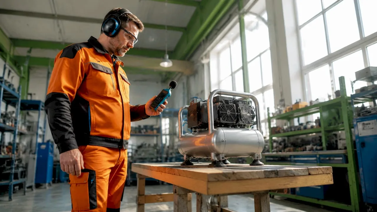
In short:
- Correct selection, sizing and quality installation are key to quiet and efficient compressor operation. Regular maintenance and suitable anti-vibration measures significantly reduce noise and extend equipment lifespan. Oil-free models are suitable for precision applications, while oil-lubricated models are reliable for more demanding industrial use.
A quiet compressor is defined as a device with a sound pressure level below 60 dB, which corresponds to the level of normal conversation. Proper tips for quiet compressor systems include selecting the right type, accurate sizing, installation on anti-vibration pads, and regular maintenance. For example, a model with a 24-litre tank and a 750 W motor achieves a noise level of 57.5 dB. Quiet operation allows the compressor to be placed directly at the workstation, eliminating pressure losses in long piping runs and increasing overall work efficiency. This guide provides specific technical recommendations for professionals who want to reduce noise and improve operating conditions.
Tips for quiet compressor systems: types and their selection
Selecting the right type of quiet compressor is the first and most important step. Each category has different noise characteristics, maintenance requirements, and suitable applications.
Oil-lubricated vs. oil-free quiet compressors
Oil-lubricated quiet compressors use lubrication to reduce friction, allowing them to operate more quietly at higher output. Their disadvantage is the need for regular oil changes and the risk of oil mist in the compressed air. Oil-free quiet compressors use special piston materials that minimize friction without lubrication. They are essential for medical, laboratory, and food industry operations where 100% air purity is required. In addition, there is no need for oil changes or disposal of oil condensates, which reduces operating costs.
Portable and vertical models
Portable quiet compressors with a smaller tank (up to 24 l) are suitable for mobile applications, auto repair shops, and workshops. Vertical models with a 50–100 l tank offer more stable pressure and are designed for permanent installation in operations. Modern piston quiet compressors with low-speed motors can deliver a flow rate of up to 295 l/min at a noise level of around 50 dB. This performance disproves the common myth that a quiet compressor necessarily means a weak compressor.
Overview of quiet compressor types
| Compressor type | Typical noise level | Recommended use |
|---|---|---|
| Oil-free piston (up to 24 l) | 55–60 dB | Workshop, car repair shop, household |
| Oil-lubricated piston (50–100 l) | 58–65 dB | Manufacturing, construction |
| Oil-free vertical (50–100 l) | 50–58 dB | Laboratory, medicine, food industry |
| Silent screw compressor | 62–72 dB | Industry, continuous operation |

Professional tip: When selecting for an industrial environment, always compare not only the dB value but also the type of noise. Screw compressors have a higher dB level, but a more even and less disruptive sound than piston models.
Oil-free models are the only correct choice for industrial applications requiring clean air. For more detailed selection criteria by application, see the industrial compressor selection guide.
How to correctly size a quiet compressor?
Incorrect sizing is the most common cause of excessive noise and reduced compressor lifespan. A compressor that is too small operates at the limit of its performance, overheats, and is noisy. One that is too large unnecessarily increases acquisition costs.
Key sizing rules
According to Atlas Copco's recommendations, two basic rules apply. First, the compressor's working pressure must be 2 bar higher than the maximum required pressure in the application. Second, the air flow must have a 15–20% reserve above the total consumption of all connected tools. This reserve ensures that the compressor does not operate at 100% output continuously, which reduces both noise and wear.
Correct sizing procedure:
- Add up the air consumption of all tools and equipment (in l/min).
- Add a 15–20% reserve for unexpected consumption peaks.
- Determine the maximum required working pressure and add 2 bar.
- Choose the tank size: a larger air tank stabilizes pressure and reduces the number of motor starts.
- Check whether the selected model can handle the duty cycle of your application.
Effect of tank capacity on noise level
A larger air tank directly reduces operating noise. A compressor with a small tank starts and stops much more frequently, and each motor start-up is louder than the running operation itself. An air tank with a capacity of 50 l or more significantly extends the intervals between start-ups and stabilizes the pressure in the piping.
| Application | Flow rate (l/min) | Recommended pressure (bar) | Minimum tank volume (l) |
|---|---|---|---|
| Pneumatic screwdriver | 100–150 | 6 bar + 2 = 8 bar | 24 l |
| Spray gun | 200–250 | 4 bar + 2 = 6 bar | 50 l |
| Pneumatic sanders | 250–300 | 6 bar + 2 = 8 bar | 100 l |
| Multiple tools simultaneously | 400+ | 8 bar + 2 = 10 bar | 200 l+ |
How to install a silent compressor for minimal noise?
The dB value on the compressor nameplate alone doesn't tell the whole story. Structural noise transmitted by vibrations into the floor, walls and workbenches can in practice be more disturbing than the direct sound of the machine. Proper installation solves this problem.
Principles for installing a silent compressor:
- Anti-vibration pads: Placing the compressor on rubber anti-vibration pads significantly reduces the transmission of vibrations into the floor and surrounding structures. Use pads with a thickness of at least 20 mm and a Shore A hardness of 40–60.
- Distance from walls: Place the compressor at least 30 cm from walls and obstacles. Proximity to walls amplifies sound reflection and increases perceived noise.
- Room ventilation: Insufficient ventilation causes overheating, which increases motor noise. Ensure the supply of fresh air and the removal of warm air from the room.
- Fixed pipe distribution: Flexible hoses transmit vibrations throughout the entire distribution system. Where possible, use fixed air distribution pipes with flexible compensators at the connection to the compressor.
- Separate room or enclosure: For industrial operations, the most effective solution is placing the compressor in a separate plant room with acoustic lining.
Professional tip: If the compressor cannot be separated into a plant room, get an acoustic enclosure made of mineral wool and perforated sheet metal. A properly designed enclosure reduces noise by 5–10 dB without limiting ventilation.
Quiet operation also allows the compressor to be placed closer to the workstation. Shorter piping runs mean lower pressure losses and higher efficiency of the entire system. More on why quiet operation is key to productivity is described in a separate article on the Kompresory-vzduchotechnika blog.

How to maintain a quiet compressor for long-term quiet operation?
Proper maintenance is a prerequisite for maintaining low noise levels throughout the compressor's service life. Neglecting maintenance leads to a gradual increase in noise, vibration, and eventually to failure.
Regular maintenance step by step
- Air filter check (every 50 operating hours): A clogged filter increases intake resistance, the motor works under higher load and becomes noisier. Clean or replace the filter.
- Tank draining (every week): Condensate in the tank causes corrosion and reduces the effective volume of the air receiver. The draining procedure is described in the guide for technicians.
- Checking and tightening connections (every 100 hours): Loose bolts and flanges are a source of vibration and noise. Check all accessible connections.
- Oil change for oil-lubricated models (per manufacturer, typically every 500 hours): Degraded oil increases friction and temperature, which results in higher noise.
- Diagnostics of noise-reducing components (once a year): Regular diagnostics extend service life and keep the compressor's noise level low.
Duty cycle and overheating
Reciprocating silent compressors are designed for intermittent operation. The recommended duty cycle is approximately 30% of total time, i.e. a ratio of 1:3 (1 minute running, 3 minutes idle). Exceeding this limit leads to motor overheating, which immediately manifests as increased noise and vibration. Screw compressors, on the other hand, are designed for continuous operation and are the right choice in industrial applications with high air consumption.
Oil-free silent compressors have lower maintenance requirements. There is no need for oil changes or cleaning of oil condensates, which saves time and waste disposal costs. However, they still require regular inspection of piston rings and valves, whose wear manifests as a drop in performance and an increase in noise.
The most common mistakes that lead to noisier operation are: operation with insufficient ventilation, overloading beyond the recommended duty cycle, neglecting air filter replacement, and lack of anti-vibration mounting. For an overview of other operational mistakes and their prevention, see the article on the most common mistakes when using compressors.
Key findings
Quiet and efficient operation of a compressor system requires the correct choice of type, precise sizing, anti-vibration installation, and regular maintenance without exception.
| Point | Details |
|---|---|
| Compressor type selection | Oil-free models are a necessity for medicine and the food industry, while oil-lubricated models are necessary for demanding industrial operation. |
| Dimensioning with a reserve | Size the flow rate with a 15–20% reserve and the pressure 2 bar above the required value. |
| Anti-vibration installation | Rubber pads and rigid piping eliminate structural noise transmitted into the building. |
| Duty cycle | Do not operate reciprocating silent compressors above 30% of the total time to avoid overheating. |
| Regular diagnostics | Annual diagnostics of components keeps noise levels low and extends the compressor's service life. |
Silent compressor in practice: what I've learned over years in operation
I have worked with compressors for a long time, and I must say that the biggest mistake I see repeatedly is confusing the dB value on the label with a guarantee of quiet operation. A compressor rated at 58 dB, placed directly on a concrete floor without anti-vibration pads and bolted to a steel table, will create unbearable noise in a workshop. The same machine on proper mounting and with short, rigid piping actually runs quietly.
The second thing that still surprises me: experts underestimate the performance of silent compressors. I have encountered operations that rejected a silent compressor for "insufficient performance," even though a vertical reciprocating model with a low-speed motor can deliver a flow rate exceeding 295 l/min. That is a performance level that covers most medium-demand industrial applications.
The third finding concerns oil-free models. Their lower maintenance requirements are a real advantage, not just a marketing phrase. In operations where I have observed a switch from oil-lubricated to oil-free compressors, maintenance costs decreased measurably. At the same time, problems with air contamination in paint shops and assembly halls disappeared.
I recommend that anyone deciding on a silent compressor start with the application and only then look for the machine. The opposite approach, i.e., buying a "silent compressor" and then figuring out what can be done with it, leads to frustration and unnecessary costs.
— Zdeněk
Silent compressors and accessories from Kompresory-vzduchotechnika
Kompresory-vzduchotechnika offers a complete range of silent compressor systems for industrial and professional applications. From oil-free reciprocating models for laboratories and auto repair shops to SCR screw compressors with low operating noise for continuous industrial operation.
The offer also includes air treatment units for clean and stable operation, pipe distribution systems and all accessories for proper installation. The Kompresory-vzduchotechnika team provides technical advice for selecting the right model according to your application, system sizing and service support. Contact us for a free technical consultation and find out which quiet compressor best suits your operating requirements.
Frequently Asked Questions
What does a quiet compressor mean and what is its noise level?
A quiet compressor is a unit with a sound pressure level below 60 dB. For example, an oil-free model with a 24-litre tank and a 750 W motor reaches a noise level of 57.5 dB, which corresponds to the level of normal conversation.
How to choose the right quiet compressor for industry?
The choice depends on the required air flow, working pressure and type of application. Size the flow with a 15–20% reserve and choose a pressure 2 bar higher than the maximum requirement of your application.
Why an oil-free quiet compressor for medicine and laboratories?
Oil-free compressors deliver 100% clean air without oil mist, which is a requirement for medical, laboratory and food industry operations. In addition, they do not require oil changes or disposal of oil condensates.
How to reduce compressor noise through installation?
Placing the compressor on anti-vibration rubber pads significantly reduces the transmission of structural noise into the floor and walls. Add rigid pipe distribution systems with flexible compensators at the connection to the compressor.
How long can a quiet piston compressor run without a break?
Quiet piston compressors are designed for intermittent operation with a recommended duty cycle of approximately 1:3, i.e. a maximum of 30% of total time. Exceeding this limit leads to overheating and increased noise. Screw compressors are suitable for continuous operation.
Recommended
- What is Cyclic Compressor Operation: Guide 2026 - Kompresory-Vzduchotechnika.cz
- A list of safety rules for working with a compressor in automotive 2026 - Kompresory-Vzduchotechnika.cz
- Factors for selecting an industrial compressor: a 2026 guide - Kompresory-Vzduchotechnika.cz
- Comparison of screw and piston compressors: a selection guide - Kompresory-Vzduchotechnika.cz

Scroll vs. Diaphragm Compressor: Key Differences

In brief:
- Scroll compressors work on the principle of two orbitally moving scrolls, which ensures continuous and quiet air compression. They are suitable for continuous industrial use with long service life and low noise, mainly in heat pumps or air conditioning systems. Diaphragm compressors use an oscillating flexible diaphragm, provide clean air, and are ideal for sensitive applications, such as in laboratories or healthcare.
The difference between a scroll compressor and a diaphragm compressor lies in the compression principle, achievable pressure, and suitability for specific operating conditions. A scroll compressor uses two eccentrically moving scrolls for continuous air compression, while a diaphragm compressor works with a flexible diaphragm that oscillates and compresses air without contact with oil. Both types belong to the category of oil-free compressors, but serve different applications. The correct choice depends on the required pressure, flow rate, purity of the output air, and the operating profile of the equipment.
How does a scroll compressor work and what is its advantage?
A scroll compressor works on the principle of two scrolls: one is fixed, the other moves eccentrically along a circular path. The moving scroll does not rotate, but performs an orbital motion. Air is drawn in at the periphery of the scrolls and gradually compressed toward the center, where it is forced out through the outlet port. This mechanism ensures continuous compression without the shocks and pulsations typical of piston compressors.
Key operating characteristics of scroll compressors:
- Low noise and vibration: The absence of reciprocating motion and a smaller number of moving parts lead to quiet operation, suitable for office and commercial environments.
- Long service life: With proper maintenance, scroll compressors achieve a designed service life of up to 15 years. This value is significantly higher than comparable piston machines.
- Resistance to liquid slugging: Scroll compressors have a high tolerance to liquid return, which is a crucial advantage in refrigeration applications and heat pumps.
- Continuous operation: Suitable for applications with high utilization and the requirement for stable air flow.
- No valve failures: Scroll technology eliminates suction and discharge valves, which are a typical failure point in piston compressors.
Typical industrial and commercial applications include heat pumps, air conditioning systems, industrial cooling circuits, and the production of clean compressed air for the food or pharmaceutical industry. Scroll compressors have almost replaced piston compressors in residential and commercial heat pumps thanks to their high efficiency and reliability. This dominance is not a coincidence: scroll technology offers a better power-to-noise ratio than any other rotary type in its power class.
Professional tip: If you operate a scroll compressor in a refrigeration circuit, regularly check the system's tightness. Refrigerant leaks reduce lubrication of the scrolls and accelerate their wear.

How does a diaphragm compressor work and where does it fit in?
A diaphragm compressor uses a flexible diaphragm as the main compression element. The diaphragm is driven by a connecting rod or hydraulically and oscillates between two positions. When moving down, it draws air into the compression chamber, and when moving up, it compresses the air and discharges it through the outlet valve. The air does not come into contact with oil or any moving metal parts. The result is an oil-free air output ideal for sensitive applications.
Design features and advantages of diaphragm compressors:
- Absolute air purity: No contact with machine oils or metals. The output air meets the requirements of laboratories, healthcare facilities, and analytical instruments.
- Low working pressure: Diaphragm compressors operate up to approximately 10 bar. This value is sufficient for most laboratory and healthcare applications, but not enough for industrial processes with higher demands.
- Quiet operation: A diaphragm compressor operates with low vibration and smooth running, suitable for noise-sensitive environments.
- Simple maintenance: The diaphragm is the most commonly serviced part. Its replacement is quick and does not require specialized tools or disassembly of the entire machine.
- Low flow rates: Diaphragm compressors are not designed for high volumetric flow rates. They are suitable for applications with low air consumption and intermittent operation.
Typical applications include laboratory analytical instruments, dental units, medical ventilators, filling of special gases, and applications in the food industry where oil contamination is unacceptable. If you are looking for an overview of oil-free compressors for various applications, the diaphragm type is one of the cleanest technologies available.
Professional tip: Replace the diaphragm preventively according to the manufacturer's recommendations, not only after a failure. A ruptured diaphragm causes an immediate stop of operation and may contaminate connected equipment.
Comparison of scroll and diaphragm compressors by key parameters
Selecting the correct type of compressor requires evaluating multiple parameters at the same time. Technicians should assess air quality, type of operation, and noise level as primary criteria. The table below summarizes the key technical and operational differences.
| Parameter | Scroll compressor | Diaphragm compressor |
|---|---|---|
| Compression principle | Two eccentric scrolls, continuous flow | Oscillating diaphragm, intermittent flow |
| Maximum pressure | 15–30 bar (industrial types) | Approximately 10 bar |
| Air flow | Medium to high | Low to medium |
| Air purity | Oil-free (oil-free version) | Absolutely oil-free |
| Noise level | Low | Very low |
| Service life | Up to 15 years with proper maintenance | Depends on the frequency of diaphragm replacement |
| Main service part | Bearings, scroll seals | Diaphragm |
| Acquisition costs | Higher | Lower to medium |
| Typical applications | Heat pumps, industry, air conditioning | Laboratories, healthcare, analytics |

Scroll compressors have higher acquisition and service costs, so correct sizing according to volumetric needs and CAGI parameters is essential for economical operation. Diaphragm compressors are more affordable, but their low flow rate and limited pressure exclude them from industrial processes with continuous air consumption.
The limitations of both technologies are just as important as their advantages. A scroll compressor is not suitable for applications with very low consumption and intermittent operation, where unnecessary wear would occur. A diaphragm compressor, on the other hand, cannot supply pneumatic tools or production lines with high air consumption. An overview of other types of industrial compressors will help complete the overall picture when choosing the technology.
Installation, maintenance, and the most common operating mistakes
Proper installation and regular maintenance determine the service life of both types of compressors. Technicians transitioning from piston to scroll or diaphragm machines encounter different servicing requirements. Knowledge of these specifics prevents unnecessary downtime and costly repairs.
Scroll compressors: critical installation requirements
- Check the direction of rotation before starting. Scroll compressors are sensitive to the direction of rotation, and incorrect phase wiring can damage the compressor within a short time. Install phase protection as a standard part of the electrical wiring.
- Ensure proper lubrication. In hermetic scroll compressors, the oil is sealed inside the machine. Check the oil level at every regular inspection and use only the oil recommended by the manufacturer.
- Limit vibration transfer to the structure. Although scroll compressors run quietly, mount them on anti-vibration pads. Vibration transfer into the piping accelerates fatigue of joints.
- Size correctly according to CAGI parameters. Overloading a scroll compressor above its rated flow shortens the life of bearings and scroll seals. Base your selection on the compressor selection guide.
- Monitor discharge temperature. Excessive discharge air temperature indicates insufficient cooling or a refrigerant leak in refrigeration applications.
Diaphragm compressors: servicing principles
- Plan preventive diaphragm replacement. The diaphragm is the most stressed part of a diaphragm compressor, and fatigue damage is common. Replacement is quick, but must be carried out before it ruptures.
- Keep spare diaphragms on site. A ruptured diaphragm stops operation immediately. Having the spare part available directly on site minimizes downtime.
- Check the tightness of suction and discharge valves. Diaphragm compressor valves are small and sensitive to contamination. Regular inspection and cleaning extends their service life.
- Do not operate a diaphragm compressor above its rated pressure. Exceeding the maximum pressure accelerates diaphragm fatigue and shortens the interval between replacements.
- Avoid the most common operating mistakes. The overview of common compressor operating mistakes applies to both types and helps prevent unnecessary failures.
Key takeaways
A scroll compressor is the choice for continuous industrial operation requiring low noise and long service life, while a diaphragm compressor is indispensable wherever absolute purity of the output air is a condition of operation.
| Point | Details |
|---|---|
| Compression principle | A scroll compressor uses the orbital motion of two scrolls, while a diaphragm compressor uses an oscillating flexible element. |
| Pressure and flow | Scroll compressors achieve higher pressures and flow rates than diaphragm compressors, which are limited to approximately 10 bar. |
| Air purity | A diaphragm compressor provides absolutely oil-free air, while a scroll compressor in oil-free design meets industrial purity standards. |
| Service life and maintenance | Scroll compressors achieve a service life of up to 15 years, while diaphragm compressors require regular replacement of the diaphragm as the main service part. |
| Selection by application | The scroll compressor belongs in industry and heat pumps, the diaphragm compressor in laboratories, healthcare, and analytical instruments. |
Practical experience: what matters in the selection
In consultations with technicians, I repeatedly encounter one mistake: choosing a compressor based on price or availability rather than on the operating profile. A scroll compressor purchased for a laboratory application with intermittent draw-off will work, but its potential will remain unused and the acquisition costs will be unnecessarily high. Conversely, a diaphragm compressor deployed in production with continuous air draw-off will fail very quickly.
The second recurring problem is underestimating the direction of rotation in scroll compressors. I have seen machines damaged within the first minutes of operation simply because an electrician connected the phases in the wrong order and phase protection was not installed. This mistake costs more than the entire installation of phase protection.
With diaphragm compressors, technicians most often neglect the preventive replacement of the diaphragm. The diaphragm lasts hundreds of operating hours, but a ruptured diaphragm stops the entire line or device immediately. I recommend setting the replacement interval 20% shorter than stated by the manufacturer, especially in operations with higher temperature or an aggressive medium.
When choosing between the two technologies, I always ask three questions: What is the required pressure and flow rate? Is absolute air purity critical? Is it continuous or intermittent operation? The answers to these three questions determine the correct type without unnecessary hesitation.
— Zdeněk
Compressors and accessories for your application
Kompresory-vzduchotechnika offers technical advice when selecting the right compressor for a specific application. Whether you are dealing with the installation of a scroll compressor for industrial operation or looking for a diaphragm type for laboratory equipment, our specialists will help you with sizing and selection.
For a complete compressed air installation, you will find pipes for air distribution in diameters of 15–28 mm for push-in systems in our range. If you need to adjust the air quality from a diaphragm compressor, air treatment units up to 10 bar provide filtration, pressure regulation, and drainage in one place. For industrial applications with higher air consumption, we also offer SCR screw compressors as an alternative to scroll types.
Frequently asked questions
What is the main difference between a scroll and a diaphragm compressor?
A scroll compressor uses two eccentric scrolls for continuous compression and achieves higher pressures and flow rates. A diaphragm compressor works with an oscillating diaphragm, ensures absolutely oil-free air, and is limited to a pressure of approximately 10 bar.
When should a diaphragm compressor be used instead of a scroll compressor?
A diaphragm compressor is the right choice wherever the purity of the output air without traces of oil is critical, for example in laboratories, medical facilities, or when filling special gases. A scroll compressor is more suitable for continuous industrial operation with higher flow rate.
How long does a scroll compressor last?
With proper maintenance, scroll compressors reach a designed service life of up to 15 years. Key factors are regular checks of the oil, system tightness, and correct direction of rotation.
How often is the diaphragm in a diaphragm compressor replaced?
The diaphragm replacement interval depends on the operating conditions and the manufacturer's recommendation. Preventive replacement before reaching the maximum interval reduces the risk of unplanned downtime.
Is a scroll compressor oil-free?
Scroll compressors are available in both oil-lubricated and oil-free versions. Oil-free scroll compressors are suitable for applications requiring clean air, but absolute oil-free operation is achieved only by diaphragm compressors, where the air does not come into contact with any lubricated parts.
Recommended
- Comparison of screw and piston compressors: a selection guide - Kompresory-Vzduchotechnika.cz
- List of advantages of screw compressors for industry - Kompresory-Vzduchotechnika.cz
- The check valve in compressors: technical function and application - Kompresory-Vzduchotechnika.cz
- Factors for selecting an industrial compressor: a 2026 guide - Kompresory-Vzduchotechnika.cz

Definition of the compressor duty cycle: a guide for technicians

TL;DR:
- The duty cycle of a compressor is the proportion of time during which the equipment operates under load, expressed as a percentage. Piston compressors should have a maximum duty cycle of 50%, while screw compressors can operate at up to 100%. Proper management and monitoring of the duty cycle extend the equipment's service life and increase its efficiency.
The duty cycle of a compressor is defined as the maximum proportion of time during which the compressor can operate under load within a given time period without overheating or suffering mechanical damage. This parameter is expressed as a percentage and directly determines how long the equipment may run relative to its rest time. The recommended duty cycle for piston compressors is generally 50%, i.e. a maximum of 30 minutes of operation per hour. Ignoring this limit leads to premature wear, increased maintenance costs, and, in extreme cases, equipment failure.
What is the definition of a compressor's duty cycle and how to understand it correctly
The definition of a compressor's duty cycle distinguishes between two different concepts that technicians often confuse in practice. The first is the mechanical cycle, which describes the physical phases of air compression inside the compressor. The second is the load (duty) cycle, which expresses the ratio of operating time under load to the total cycle time, including idle time.
The duty cycle of a compressor must be distinguished from simple operating time. A piston compressor with a duty cycle above 50% may be undersized for a given application, even though it still technically works. The result is gradual thermal stress on the motor windings, bearings, and piston rings, which only becomes apparent after extended operation.
The industry standard is based on a simple formula: duty cycle (%) = (operating time / total cycle time) × 100. If a compressor runs for 20 minutes and then rests for 20 minutes, its duty cycle is 50%. This calculation forms the basis for selecting the right equipment according to the operational needs of a specific production line or workshop.
How a compressor works and what phases make up its cycle

The duty cycle includes three main mechanical phases: intake, compression, and discharge of air. These phases repeat with every rotation of the crankshaft in piston compressors or every rotation of the rotors in screw compressors. Understanding these phases is a prerequisite for proper fault diagnosis and operational optimization.
Phases of the piston compressor's duty cycle:
- Intake: The piston moves down, the vacuum opens the intake valve, and air enters the cylinder.
- Compression: The piston moves up, both valves are closed, and the air is compressed to the required pressure.
- Discharge: When the set pressure is reached, the discharge valve opens and compressed air flows into the air receiver.
- Idle phase: The compressor stops after reaching the upper switch pressure and waits for the pressure to drop below the lower limit.
The difference between the mechanical and loading cycle has a direct impact on the quality of compressed air. If the idle phases are too short, the air in the piping does not have enough time to cool down and condense moisture, which increases the water content in compressed air. This is a critical factor especially in paint shops, the food industry, or electronics manufacturing, where moisture causes direct damage to products.
Screw compressors operate on a different principle. Two screw rotors rotate in opposite directions, and air is progressively compressed along their length without interruption. This continuous process eliminates the pressure pulsations typical of piston compressors and allows operation at a higher duty cycle without thermal stress.

Professional tip: When diagnosing compressor overheating, always first check the actual duty cycle over the last 8 hours of operation. Overheating caused by exceeding the recommended duty cycle manifests earlier than failure caused by a mechanical fault.
How does the duty cycle differ between compressor types?
The choice of the right compressor directly depends on the required duty cycle in operation. Screw compressors are designed for continuous operation with a duty cycle of up to 100%, while piston compressors are designed for intermittent operation. Ignoring this difference leads to excessive wear and higher maintenance costs.
| Compressor type | Recommended duty cycle | Typical applications | Cooling |
|---|---|---|---|
| Single-stage piston | 25–50 % | Workshops, service, intermittent operation | Air-cooled |
| Two-stage piston | 50–75 % | Medium production, more demanding applications | Air-cooled or oil-cooled |
| Rotary screw | 75–100 % | Industrial production, continuous operation | Oil-cooled or water-cooled |
| Oil-free screw | 75–100 % | Food industry, pharmaceuticals, electronics | Air-cooled or water-cooled |
Piston compressors with a duty cycle above 50% overheat because their air cooling cannot sufficiently dissipate the heat generated by compression. This results in degradation of the lubricating oil, shortened piston ring life, and in extreme cases, piston seizure. Screw compressors have integrated oil cooling with a thermostatic valve that maintains the operating temperature within the optimal range regardless of the duration of operation.
Professional tip: If your production requires compressed air for more than 6 hours a day or a duty cycle above 60%, switching to a screw compressor typically pays back in maintenance and energy savings within 2 to 3 years. For a detailed comparison of parameters, see the overview of screw and piston compressors.
When selecting equipment based on the duty cycle, a margin must be factored in. If the application requires a 40% duty cycle, select a compressor with a recommended maximum of 50% or higher. Operating at the limit of the maximum duty cycle shortens the equipment's service life even when technical limits are observed, because thermal stress accumulates.
How does automation control the duty cycle and protect the equipment?
The pressure switch automatically controls the compressor's duty cycle through set cut-in and cut-out pressures, typically ranging from 0.6 to 0.8 MPa. The compressor starts when the pressure drops below the lower limit and stops when it reaches the upper limit. Correct setting of this range directly affects the number of starts per hour and thus the overall duty cycle.
Optimizing the duty cycle through automation involves four key steps:
- Setting the pressure switch range: A larger difference between the cut-in and cut-out pressure extends the idle phases and reduces the number of starts per hour. The recommended difference is at least 1.5 bar.
- Installing a variable frequency drive (VSD): The inverter adjusts the motor speed to the current air consumption. The compressor does not need to start and stop cyclically, but instead regulates its output continuously. Installing a VSD significantly improves efficiency and reliability.
- Monitoring operating hours and number of starts: Modern control units record the number of cycles per hour, total operating hours, and temperature profiles. This data forms the basis for predictive maintenance.
- Setting the minimum discharge pressure: Too low a minimum pressure causes unnecessarily frequent starts. Correct setting reduces the duty cycle and extends motor service life.
Frequent start-stop cycles increase wear and reduce operating efficiency. Each motor start generates an inrush current several times higher than the rated current, which stresses the windings and starting capacitors. Limiting the number of starts to a maximum of 10 per hour is a standard industry recommendation for piston compressors.
Professional tip: When installing a VSD, verify compatibility with the existing pressure switch. Some older switches are not designed for continuous regulation and may cause pressure instability in the network.
Practical methods for monitoring and optimizing the duty cycle
Monitoring the duty cycle in real operation requires specific tools and methodology. Without measured data, it is impossible to distinguish whether the compressor is operating in an optimal regime or approaching critical overload.
Tools and methods for measuring the duty cycle:
- Hours of operation and hours under load: Most industrial compressors have separate counters for total hours of operation and hours of operation under load. The ratio of these values indicates the actual duty cycle over the monitored period.
- Temperature data logger: Continuous recording of discharge air and oil temperature reveals overheating trends before a failure occurs. The critical discharge air temperature for reciprocating compressors is generally 160 °C.
- Compressed air network analyzer: Devices such as the Fluke 721 or systems from Kaeser Kompressoren record pressure profiles and identify air leaks that increase the duty cycle.
- Thermal imaging camera: An infrared thermal imaging camera reveals overheated motor parts, bearings, or valves without the need to shut down the compressor.
| Parameter | Normal range | Critical value | Recommended action |
|---|---|---|---|
| Discharge air temperature | up to 120 °C | above 160 °C | Check cooling and oil |
| Number of starts per hour | max. 10 | over 15 | Adjust pressure switch or air tank |
| Duty cycle | up to 50% (piston) | over 65% | Consider replacing with a screw compressor |
| Oil temperature | 70–90 °C | over 100 °C | Check the thermostat and cooler |
Heat generated by compression is a key factor affecting the lifespan and operational efficiency of compressors. In large industrial facilities, this heat can be utilized through heat recovery systems for heating water or heating operational spaces, bringing measurable savings in operating costs. Heat recovery is a standard feature of modern screw compressors from manufacturers such as Atlas Copco or Kaeser.
When optimizing the duty cycle in a production environment, seasonal effects must also be taken into account. During the summer months, the intake air temperature rises, the compressor must dissipate more heat, and the duty cycle lengthens for the same air consumption. A preventive check of the cooling system before the summer season is a standard part of planned maintenance.
Key findings
The compressor duty cycle is a critical parameter that determines the maximum safe load on the equipment and directly affects its lifespan, efficiency, and maintenance costs.
| Point | Details |
|---|---|
| Definition of duty cycle | The ratio of operating time under load to the total cycle time, expressed as a percentage. |
| Limit for reciprocating compressors | The recommended maximum is 50%, i.e., 30 minutes of operation per hour. |
| Screw compressors | Designed for operation at up to 100% duty cycle, suitable for continuous production. |
| Automation and VSD | Inverters and properly set pressure switches reduce the number of starts and extend service life. |
| Monitoring and Predictive Maintenance | Monitoring temperature, number of starts, and operating hours enables early detection of problems. |
Practical experience: what technicians underestimate
I have worked with compressors in industrial environments for many years and repeatedly encounter the same problem. Technicians monitor pressure and flow, but ignore the duty cycle until the moment the compressor fails. Yet this very parameter is the simplest indicator of whether the equipment is correctly sized for the given application.
The most common mistake I see is installing a piston compressor in an operation where air is consumed continuously. The compressor runs at a 70 or 80% duty cycle, overheats, the oil degrades faster, and service intervals shorten. The operator deals with this through repeated repairs instead of investing once in a screw compressor with advantages for industrial operation.
The second thing that surprises me is the underestimation of data from control units. Modern compressors record hundreds of operating parameters, but most operators only read the hours until service. Analyzing duty cycle trends over the past 30 days can predict a failure a week in advance. That is the difference between a planned shutdown and an unplanned breakdown in the middle of production.
I recommend that every technician set up a monthly check of the actual duty cycle as a standard part of preventive maintenance. It is enough to compare the load hours with the total operating hours and compare the result with the manufacturer's recommendation. If the numbers approach the maximum, it is time to act. Switching to a two-stage compressor or installing a VSD are concrete steps that have repeatedly proven effective in practice.
— Zdeněk
Products for optimal duty cycle management
Kompresory-vzduchotechnika offers technical solutions for every stage of duty cycle optimization, from basic control to comprehensive compressed air treatment.
Essential for stable and clean compressed air are the air treatment units, which regulate pressure, filter condensate and lubricate pneumatic components. Proper air treatment reduces back-pressure surges that extend the compressor's duty cycle. Kompresory-vzduchotechnika provides expert advice on selecting control components and accessories for industrial and workshop applications. The full range of compressors and pneumatic equipment can be found at kompresory-vzduchotechnika.cz.
FAQ
What is a compressor duty cycle?
The compressor duty cycle is the maximum proportion of operating time under load within a given time period, expressed as a percentage. For example, a 50% duty cycle means a maximum of 30 minutes of operation per hour.
What is the recommended duty cycle for a piston compressor?
The recommended duty cycle for piston compressors is generally 50%. Exceeding this limit leads to overheating, faster oil degradation, and a shorter service life of the equipment.
Can screw compressors operate continuously?
Yes, screw compressors are designed for continuous operation with a duty cycle of up to 100%. Their integrated oil cooling ensures a stable operating temperature regardless of the length of operation.
How does an inverter (VSD) affect the duty cycle?
An inverter adjusts the motor speed to match the current air demand, so the compressor does not need to cyclically start and stop. The result is fewer starts per hour, lower thermal stress, and a longer service life of the equipment.
How do I know if a compressor is operating with too high a duty cycle?
The most reliable indicator is comparing the loaded hours with the total operating hours over the monitored period. If the resulting ratio exceeds the manufacturer's recommendation, or if the compressor starts more than 10 times per hour, the duty cycle is too high.
Recommended
- What is Cyclic Compressor Operation: Guide 2026 - Kompresory-Vzduchotechnika.cz
- Compressor bleeding procedure: a guide for technicians - Kompresory-Vzduchotechnika.cz
- Factors for selecting an industrial compressor: a 2026 guide - Kompresory-Vzduchotechnika.cz
- The role of lubrication in a compressor: a guide for technicians - Kompresory-Vzduchotechnika.cz

Pneumatic Tools in 2025: Trends and Innovations

TL;DR:
- In 2025, pneumatic tools are characterized by compact design, lighter materials, and IoT sensors enabling predictive maintenance. Key innovations include flexible articulated constructions, advanced materials, and the integration of IoT technologies to increase efficiency and reliability. Proper selection and regular maintenance ensure long service life and optimal performance of systems in industry and service applications.
Pneumatic tools in 2025 are defined by three key shifts: compact construction for working in confined spaces, integration of intelligent sensors for predictive maintenance, and advanced materials reducing weight while maintaining performance. Models such as the ZIW340FA and ZIW410FA from China Pneumatic Corporation show where the development of pneumatic tools in industry, construction, and automotive service is heading. IoT integration enables real-time monitoring of tool condition, which reduces unplanned downtime and extends the lifespan of the entire system. The new generation of pneumatic tools brings measurable benefits for operational efficiency, which is why an overview of current technologies is essential for every professional who wants to keep their operation competitive.
What are the main innovations affecting pneumatic tools in 2025?
The development of pneumatic tools over the past two years has brought several technological shifts that have a direct impact on productivity in industrial operations. These are not cosmetic changes. They are fundamental structural redesigns of the tools.
Key innovations include:
- Dual-Flex articulated construction. China Pneumatic Corporation has introduced the ZIW340FA and ZIW410FA angle impact wrenches with two flexible joints. These models allow access to places where standard impact wrenches physically cannot fit, for example behind vehicle engines or inside body frame profiles.
- Advanced materials. Composite tool bodies made of aluminum alloys and engineering plastics reduce weight by 15 to 25% compared to older steel constructions. Lower weight directly reduces operator fatigue during repetitive work.
- Intelligent sensors and IoT. The integration of IoT sensors into pneumatic tools enables monitoring of pressure, temperature, and the number of work cycles. Predictive maintenance based on this data reduces the risk of unexpected failures on critical production lines.
- Ergonomics and safety. New models include non-slip surfaces, vibration damping, and ergonomically shaped handles. These features directly affect compliance with occupational health and safety standards and reduce the risk of occupational diseases caused by vibration.
- Energy savings. Modern 2025 pneumatic technologies operate with optimized airflows that reduce compressed air consumption while maintaining performance.
Professional tip: When acquiring new tools with IoT functions, verify the compatibility of their communication protocol with your existing production management system. Incompatible systems mean that data from the sensors will remain unused.
Trends in pneumatic tools clearly show that the future belongs to tools that are not only more powerful but also "smarter" and better adapted to specific applications. Automation of pneumatic tools is ceasing to be the privilege of large manufacturing plants and is becoming accessible to medium-sized service centers and workshops as well.

How to choose the right pneumatic tools for industry and service?
Choosing pneumatic tools without the correct technical foundation leads to undersized or oversized tools, with negative impacts on operation in both cases. The correct selection process is based on specific calculations and knowledge of the application.
- Calculate the required force. The calculation of force F = P × A is the basic step in sizing a pneumatic actuator. Add a safety factor of 25 to 30% to the result due to friction and system losses. This procedure ensures that the tool will operate in the optimal performance range, not at the limit of its capabilities.
- Define the type of application. Light assembly in electronics requires different parameters than heavy industrial assembly or truck servicing. Torque, rotation speed, and tool dimensions must match the specific work task.
- Choose the correct type of drive. Rodless cylinders save space and allow longer strokes in compact automated machines, but have lower side load capacity. For applications with high side loads, conventional cylinders with profiled rods or external guide systems are more suitable.
- Compare the parameters of the models. When choosing between models, pay attention to torque, air consumption in l/min, working pressure in bar, and tool dimensions. These four parameters form the basis of comparison.
- Take accessibility and ergonomics into account. For working in confined spaces, for example in vehicle underbodies or inside machines, compact dimensions and an articulated design are key.
Professional tip: The performance of a pneumatic tool cannot be evaluated by price alone. Correct force calculation with a safety margin is crucial for maintaining the efficiency and service life of the entire system.
Comparison of tools by application
| Application type | Recommended tool | Key parameter |
|---|---|---|
| Automotive service, heavy-duty assembly | ZIW410FA angle impact wrenches | High torque, articulated head |
| Surface preparation, renovation | Pneumatic sandblasting gun | Nozzle type, air consumption |
| Grinding and cutting in the workshop | MSW pneumatic die grinder | Speed up to 25,000 rpm |
| Industrial automation | Rodless pneumatic cylinder | Stroke length, side load |
| Easy installation, electronics | Compact pneumatic screwdriver | Torque, precision |

Choosing the right tools for the application directly affects work speed, result quality, and maintenance costs. An overview of available models and their technical data can be found in the drive selection guide.
Where are the latest pneumatic tools used in practice?
Practical deployment of new pneumatic tools in industry, construction, and automotive service shows that technological innovations have a measurable impact on productivity and quality of work.
- Automotive service. Angle impact wrenches with Dual-Flex construction, such as the ZIW340FA and ZIW410FA models from China Pneumatic Corporation, enable tightening bolts in places standard tools cannot reach. A typical example is the assembly of chassis components or work in the engine compartment of compact vehicles, where access is limited to a few centimeters.
- Surface preparation and renovation. Pneumatic sandblasting guns use various nozzles and abrasive materials for effective removal of rust, old coatings, and dirt. Performance and air consumption depend on the type of gun and the chosen abrasive, with the correct combination directly affecting the speed and quality of surface preparation before further treatment.
- Industrial grinding and cutting. The MSW pneumatic die grinder, with a speed of up to 25,000 rpm and a set of grinding stones and cutting discs, covers a wide range of applications from fine weld grinding to rough cutting in metalworking. Ergonomic design and quick tool changes increase comfort during long-term use.
- Construction and structural assembly. Pneumatic nailers and staplers remain the standard on construction sites, where speed and reliability are emphasized. New models with lower weight and better recoil damping reduce worker fatigue during all-day operation.
- Industrial automation. Rodless pneumatic cylinders are used in compact automated lines where space is limited and longer strokes are required. Their deployment in packaging and assembly machines is growing as manufacturers seek to save space while maintaining performance.
The new pneumatic tools of 2025 bring specific benefits to users in these industries: shorter task completion time, reduced physical strain on operators, and higher repeatability of results. These factors directly translate into operating costs and the competitiveness of the operation.
How to extend the service life of pneumatic tools and ensure reliable operation?
Proper maintenance and system sizing are crucial for the service life of pneumatic tools. Most premature failures are not caused by wear, but by errors in operating practice, which are easily avoidable.
- Oversize the compressor's output. Compressor output must be oversized by at least 20% compared to the theoretical tool consumption. A pressure drop caused by an overloaded compressor reduces tool performance and leads to unplanned downtime. A screw compressor with reserve output is standard for industrial operations with multiple tools.
- Regularly inspect and replace seals. Leaks in compressed air distribution cause a pressure drop and increase energy costs. Seal inspection should be part of a regular monthly check.
- Lubricate moving parts. Pneumatic tools with moving metal parts require regular lubrication with oil designed for pneumatic tools. Insufficient lubrication is the most common cause of premature wear in rotary tools.
- Clean and dry the compressed air. Moisture and impurities in compressed air damage the internal components of tools. Installing water separators and filters on the distribution system is a basic requirement for reliable operation.
- Monitor operating parameters using sensors. For tools equipped with IoT sensors, use data on cycle count and temperature to plan preventive maintenance. A predictive approach is significantly cheaper than reactive repairs after a failure.
- Choose the right accessories. Selecting a cylinder with anti-rotation protection must take into account load, space constraints, and required precision. Unsuitable accessories shorten the service life of the entire system.
Professional tip: The most commonly overlooked step in maintenance is checking safe tool usage and the condition of air hoses. A cracked or worn hose causes pressure losses that manifest as "weak tool performance," even though the tool itself is fine.
The efficiency of pneumatic tools depends on the entire system, not just the tool itself. The compressor, distribution system, air treatment, and regular maintenance form a whole, in which every link affects the resulting performance.
Key takeaways
Pneumatic tools in 2025 achieve the highest efficiency when they are correctly sized, regularly maintained, and selected according to the specific application using current technologies.
| Point | Details |
|---|---|
| Compressor sizing | Oversize the compressor output by at least 20% compared to the nominal tool consumption. |
| Calculating actuator force | Use the formula F = P × A and add a safety factor of 25 to 30% for reliable operation. |
| Tool selection according to application | Articulated wrenches for confined spaces, die grinders for grinding, sandblasting guns for surface preparation. |
| IoT and predictive maintenance | Sensors in tools enable maintenance to be planned before a failure occurs, not after. |
| Regular system maintenance | Checking seals, lubrication, and air cleanliness are crucial for tool service life. |
Pneumatics in practice: what really determines performance
I have been working with pneumatic tools and systems for many years, and I repeatedly encounter the same problem: operators invest in quality tools but neglect the system that powers them. They buy a powerful impact wrench, but the compressor cannot cover peak consumption when multiple tools are running simultaneously. The result is predictable. The tool underperforms, the operator complains about "weak tools" and the fault is looked for in the wrong place.
The second recurring problem is underestimating ergonomics. New models with composite bodies and vibration damping are not just a marketing feature. These are tools that reduce the risk of occupational diseases and maintain operator productivity throughout the entire shift, not just in the first two hours. Investment in ergonomically better tools pays off in lower sickness rates and higher quality of work.
What really interests me about the current development of pneumatic technologies 2025 is IoT integration. Predictive maintenance based on sensor data is an approach the industry knows from large machines. Transferring it to hand tools is a logical step, but it requires operators to have a system for collecting and evaluating data. Without this, sensors are pointless. I recommend starting simply: track the number of work cycles and plan replacement of wear parts based on data, not estimation.
The future of pneumatic tools belongs to tools that are smarter, lighter and more adaptable. But the fundamentals remain the same. Correct sizing, clean and dry air, regular maintenance. Technology has not abolished these fundamentals. It has only added new possibilities to them.
— Zdeněk
Equip your operation with Kompresory-vzduchotechnika
Kompresory-vzduchotechnika offers a complete range for professional pneumatic operations: from SCR screw compressors with reserve power for industrial applications to air treatment units ensuring clean and dry air for reliable tool operation.
The range also includes compressed air distribution systems, M7 pneumatic guns for surface preparation, and complete accessories for installation and service. The Kompresory-vzduchotechnika team provides expert technical advice on component selection and system sizing. Contact us or visit the website for an overview of the current offer and technical specifications of the products.
FAQ
What are pneumatic tools in 2025?
Pneumatic tools in 2025 are tools powered by compressed air, equipped with advanced materials, compact design, and in new models also IoT sensors for monitoring operation. Compared to older generations, they offer lower weight, better ergonomics and higher performance with lower air consumption.
How to choose the right pneumatic tool for industrial operation?
The selection is based on calculating the required force using the formula F = P × A with a safety factor of 25 to 30%, the type of application, and the required parameters such as torque and tool dimensions. Comparing models based on air consumption and working pressure is essential before every purchase.
Why is it necessary to oversize the compressor by 20%?
An overloaded compressor causes a drop in operating pressure, which reduces tool performance and leads to unplanned downtime. Oversizing by at least 20% compared to the nominal tool consumption ensures stable pressure even under peak load.
What are the advantages of rodless cylinders in industrial automation?
Rodless cylinders save space and allow longer strokes in compact automated lines, but they have a lower side load capacity than conventional cylinders. For applications with high side loads, cylinders with profiled rods or external guide systems are more suitable.
How do IoT sensors improve the operation of pneumatic tools?
IoT sensors integrated into pneumatic tools monitor pressure, temperature, and the number of operating cycles in real time. This data enables predictive maintenance, which reduces the risk of unexpected failures and extends tool lifespan in critical industrial conditions.
Recommended
- How pneumatics works: a complete guide for industry 2026
- What is pneumatic automation: a guide for industry - Kompresory-Vzduchotechnika.cz
- Pneumatic spring cylinder: principle, specifications and use - Kompresory-Vzduchotechnika.cz
- What is pneumatic lubrication: a guide for technicians - Kompresory-Vzduchotechnika.cz

List of Professional Spray Guns 2026: A Guide for Technicians

TL;DR:
- A professional spray gun is designed for the even application of paints, varnishes and stains over large surfaces, and depends on the nozzle diameter, the bowl volume and the working pressure. Choosing the right type, for example HVLP or airless, affects work efficiency and material consumption on different types of surfaces. Quality spray guns from brands such as DeVilbiss, Sata, Iwata or Walther Pilot ensure precision, long service life and professional results.
A professional spray gun is defined as a pneumatic or electric device designed for the even application of paints, varnishes and stains over large surfaces with controlled material flow. The correct choice from the available list of professional spray guns depends on three key parameters: nozzle diameter, bowl volume and working pressure. Brands such as DeVilbiss, Sata, Iwata or Walther Pilot are among the reference manufacturers in the field. This overview provides a technically grounded comparison of models and types for professional craftsmen and painters who need reliable equipment for everyday work.
1. Key types of spray guns and their technical parameters
Professional spraying equipment is divided into four main categories: HVLP, LVLP, APS and airless. Each technology has different compressor requirements and different results on the surface. Choosing the right technology is the basis for efficient work without unnecessary material losses.
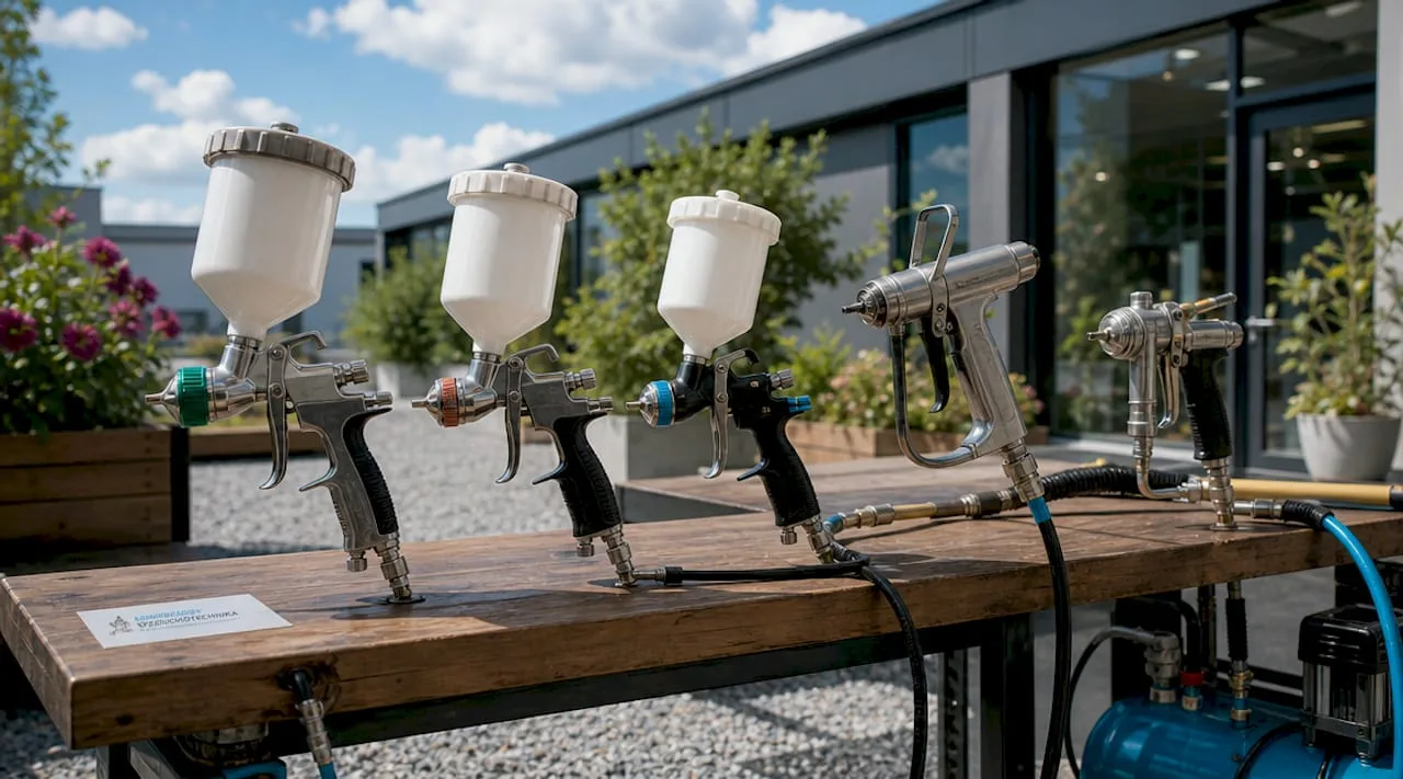
HVLP (High Volume Low Pressure) works with a high volume of air and low output pressure. This technology achieves high material transfer efficiency, typically 65 to 85%, and minimizes waste from atomization. HVLP spray guns are the standard in car body shops and joinery workshops.
LVLP (Low Volume Low Pressure) combines a low volume of air with low pressure. The advantage is lower air consumption compared to HVLP, so these spray guns also work with less powerful compressors. They are suitable for fine painting and work in smaller workshops.
APS (Air Pressure Spray) is a conventional technology with higher working pressure. It provides a very fine spray and fast application, but with higher material waste. It is used where speed and surface fineness are the priority.
Airless spray guns work without compressed air. The material is pushed by a pump directly through the nozzle at high pressure. They are ideal for large surfaces and dense materials such as facade paints or primers.
Professional HVLP, LVLP, APS spray guns have a working pressure of 3 to 6 bar and air consumption of 160 to 300 l/min. This means that for stable spraying you need a compressor with an output of at least 200 l/min and a tank of at least 50 litres.
| Technology | Working pressure | Air consumption | Typical use |
|---|---|---|---|
| HVLP | 1.5 to 3 bar | 200 to 300 l/min | Paints, varnishes, car paint shops |
| LVLP | 1.5 to 2.5 bar | 160 to 220 l/min | Fine paints, smaller workshops |
| APS | 3 to 6 bar | 200 to 350 l/min | Fast application, industry |
| Airless | without air | pump | Facades, primers |
Professional tip: For selecting the nozzle diameter, a direct rule applies: nozzles 0.5 to 1.4 mm are intended for paints and thin materials, while nozzles 1.7 to 2.5 mm are for thick decorating paints and primers. A bowl volume of 0.5 to 0.8 l is the optimal compromise for most professional work.
2. Ten best professional spray guns: model comparison
The following overview includes models that have proven themselves in professional operation. Each model is evaluated according to technical parameters, typical use, and performance-to-price ratio.
DeVilbiss GTi Pro Lite
DeVilbiss GTi Pro Lite is an HVLP gun designed for car paint shops and fine painting. The nozzle is available in diameters of 1.2, 1.3, and 1.4 mm. The gun body is made of anodized aluminum, with a weight of approximately 490 g. The gun is popular for its exceptionally even spray pattern and low paint consumption.
Sata Jet 5000 B HVLP
Sata Jet 5000 B is the reference model for professional painters. It offers nozzles from 1.2 to 1.8 mm and an ergonomic body with precise flow regulation. Air consumption is approximately 220 l/min at a pressure of 2 bar. Sata is synonymous with precision and long service life in demanding operation.
Iwata LPH-400
Iwata LPH-400 is a Japanese-made HVLP gun with a 1.3 or 1.4 mm nozzle. It features exceptionally fine atomisation of material and low paint consumption. The gun is popular in car paint shops as well as in industrial painting thanks to precise air cap regulation.
Walther Pilot WA 500
Walther Pilot WA 500 is an industrial HVLP gun with a nozzle of 1.4 to 2.0 mm. It is suitable for painting furniture, metal structures and industrial parts. The body is made of durable aluminium, the bowl has a volume of 600 ml. The gun can handle both thinned paints and thicker primers.
Kinekus Profi Jet S
Kinekus Profi Jet S is an HVLP gun with a 1.4 mm nozzle, working pressure of 3 to 6 bar and a 600 ml bowl. Air consumption of 160 to 300 l/min places it in the category of guns for powerful compressors. It is an affordable choice for tradespeople looking for a reliable basis for everyday work.
Graco Finishline 4 FLX
Graco Finishline 4 FLX is an HVLP gun with an adjustable nozzle from 1.0 to 1.8 mm. It allows spraying of both water-based and solvent-based materials. The bowl has a volume of 1 litre, the body is made of durable polymer. Graco is popular in carpentry workshops and for furniture painting.
Wagner Control Pro 350 M
Wagner Control Pro 350 M is an electric airless gun designed for facade paints and primers. It works without a compressor, the pump generates pressure of up to 210 bar. The 0.023 inch nozzle (approximately 0.58 mm) ensures fine atomisation even with thick materials. The gun is suitable for large areas and fast application.
Electric HVLP gun 1200 W
The electric HVLP gun from one of the premium global brands has a power input of 1200 W. The nozzle is adjustable from 1.8 to 3.0 mm, and the bowl has a capacity of 1.5 l. The gun handles paints, varnishes, and stains without the need for a compressor. It is a practical choice for craftsmen who do not work with a pneumatic system.
HIGH-END Z10507 cordless gun
The Z10507 cordless gun with a 36V Li-Ion battery, a bowl capacity of 800 ml, and a power of 800 W provides freedom of movement without being limited by a cable or hose. This technology is suitable for work on scaffolding, roofs, or in areas without an air supply. The uniform spray pattern is comparable to lower-class pneumatic guns.
Fuji Semi-PRO 2 HVLP
The Fuji Semi-PRO 2 is a turbine HVLP gun with its own turbine instead of a compressor. The working pressure is stable regardless of the hose length. The nozzle is available in diameters from 1.0 to 1.8 mm, and the bowl has a capacity of 400 ml. The gun is popular for furniture finishing and detail work, where precision is key.
Professional tip: When choosing a gun for an auto body shop, always check the compatibility of the air cap with the nozzle. An incorrect combination causes asymmetric atomization, which shows up as streaks on the surface.
3. How to choose a professional spray gun according to the type of work
The choice of gun depends primarily on the material you will be applying and the scope of work. There is no universal model for all situations.
For auto body shops and fine finishes, choose HVLP guns with a 1.2 to 1.4 mm nozzle. These guns provide the finest atomization and minimal material loss. The brands DeVilbiss, Sata, and Iwata are the standard in this segment.
For painting work and facade paints, guns with a 1.7 to 2.5 mm nozzle or airless systems are suitable. Correct paint viscosity is crucial for a flawless spray application. Professional painters measure viscosity with a viscometer before each spraying job.
When choosing, also consider the frequency of use. Guns for everyday professional use must have an easily disassemblable body and available spare parts. Cheap guns without service support can end up being more expensive than a pricier model with full manufacturer support.
Pneumatic guns require a powerful compressor. For stable operation with an HVLP gun, you need a compressor with a minimum air consumption matching the gun's parameters. Information on optimizing compressed air consumption will help you set up the system efficiently and reduce operating costs.
Procedure for correctly setting up the gun before work:
- Check the nozzle diameter and select the corresponding air cap.
- Set the working pressure on the compressor according to the gun manufacturer's recommendations.
- Measure the paint viscosity with a viscometer and adjust the consistency with thinner if necessary.
- Set the spray fan width and material flow rate on the gun.
- Perform a test spray on cardboard and check the pattern uniformity.
- Adjust the distance of the gun from the surface to 20 to 25 cm and maintain a perpendicular angle.
4. Comparing a spray gun with a roller: when to use which
A spray gun is more efficient than a roller for large areas. A roller, on the other hand, is faster and more practical for small or intricate spaces. This decision has a direct impact on working time and the resulting surface quality.
The gun applies material evenly and without tool marks. The resulting surface is smoother and more professional, especially with paints and enamels. However, preparation before spraying is more time-consuming: masking off surrounding surfaces, preparing the paint, and cleaning the gun after work takes longer than with a roller.
| Parameter | Spray gun | Roller |
|---|---|---|
| Speed on large surfaces | High | Medium |
| Surface quality | Very smooth | Slight texture |
| Preparation and cleanup | More demanding | Simple |
| Suitability for complex surfaces | Limited | High |
| Material consumption | Lower (HVLP) | Higher |
| Purchase cost | Higher | Low |
The choice between a spray gun and a roller depends on the scope of the job. For surfaces over 50 m², a spray gun always pays off. For small repairs or work in corners and behind radiators, a roller or brush is more practical.
Key findings
A professional spray gun requires the right combination of nozzle diameter, working pressure, and material viscosity to achieve a professional result without streaks or blotches.
| Point | Details |
|---|---|
| Nozzle diameter | Nozzles 0.5 to 1.4 mm for paints, 1.7 to 2.5 mm for thick paints and primers. |
| Spray gun technology | HVLP is the standard for car body shops, airless for façades and large surfaces. |
| Working pressure | Professional spray guns require a compressor with an output of 160 to 300 l/min and a pressure of 3 to 6 bar. |
| Material viscosity | Measuring viscosity with a viscometer before each spraying session prevents streaks and uneven surfaces. |
| Distance and angle | An optimal distance of 20 to 25 cm and a perpendicular angle of 90° are prerequisites for an even spray coat. |
Practical experience: what determines spray coat quality
I have worked with professional spray guns for years, and I can say that the biggest mistakes craftsmen make are not in choosing the gun, but in preparing the paint and setting up the equipment. A spray gun worth thousands of crowns won't help if the paint is improperly thinned or the pressure is set by guesswork.
Failure to maintain a distance of 20 to 25 cm and a perpendicular angle to the surface is the most common cause of streaks and uneven spraying. I see this repeatedly even with experienced craftsmen switching to a new gun model. Each gun behaves slightly differently, and the first spray should always be a test run on cardboard.
The second thing that gets underestimated is maintenance. A gun that is not thoroughly cleaned after every job will start clogging the nozzle and air channels. The result is dripping, uneven atomization, and eventually a damaged seal. Cleaning the gun takes 10 minutes and extends the equipment's lifespan by years.
As for choosing a specific model, I recommend starting with a spray gun that has an established service network and available spare parts in the Czech Republic. Sata, DeVilbiss, and Iwata meet this requirement. Cheaper models without service support may be tempting due to their price, but a breakdown during the season can halt your work for days.
— Zdeněk
Professional gun and accessory kits at Kompresory-vzduchotechnika.cz
Kompresory-vzduchotechnika offers professional craftsmen and painters a complete range of spray guns and pneumatic accessories. The selection includes guns for auto body shops, carpentry workshops, and industrial applications.
Professional gun kits intended directly for demanding operation are available on the Kompresory-vzduchotechnika.cz website. The range includes HVLP and LVLP guns as well as accessories for proper air treatment. The team of technical advisors provides support in selecting the right model according to specific working conditions. For an overview of the entire range of pneumatic tools, visit the website or contact technical support directly.
FAQ
What is an HVLP gun and why do professionals use it?
An HVLP (High Volume Low Pressure) gun works with a high volume of air and low output pressure, achieving high material transfer efficiency and minimal waste. Professionals prefer it for fine painting, auto body shops, and work where surface quality is key.
What compressor do I need for a professional spray gun?
Professional air guns have an air consumption of 160 to 300 l/min and a working pressure of 3 to 6 bar. For stable spraying, you need a compressor with a capacity of at least 200 l/min and an air tank of at least 50 liters.
What nozzle diameter should I choose for painting furniture?
For painting furniture and fine paints, nozzles of 1.0 to 1.4 mm are suitable. Nozzles of 1.7 to 2.5 mm are intended for thick paint colors and base coats on larger surfaces.
When is a roller better than a spray gun?
A roller is more practical for small areas, intricate spaces and quick repairs. A spray gun pays off on areas above 50 m², where it saves time and delivers a smoother finished surface.
How to properly maintain a professional spray gun?
After each use, completely disassemble the gun and clean all parts with thinner or a cleaning agent recommended by the manufacturer. Regular maintenance prevents nozzle clogging and extends the service life of both the seals and the entire device.
Recommended
- A guide to choosing pneumatic hoses for auto repair shops 2026 - Kompresory-Vzduchotechnika.cz
- What is pneumatic lubrication: a guide for technicians - Kompresory-Vzduchotechnika.cz
- M7 pneumatic washing, spray and sandblasting guns – surface preparation from washing to blasting
- The role of lubrication in a compressor: a guide for technicians - Kompresory-Vzduchotechnika.cz

How to set up a compressed air distribution system step by step
We have merged this article with a more detailed and more up-to-date guide on the same topic. Continue here: A guide to industrial air distribution: efficiency of operation.

Outdated article: discount portals
This article is no longer current. Continue here: compressed air blog.

Compressor air bleeding procedure: a guide for technicians
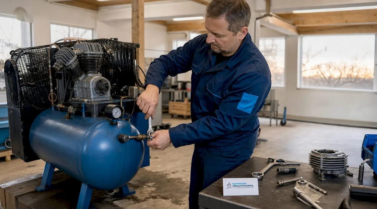
TL;DR:
- Bleeding a compressor is necessary before every service to prevent damage and hazards. Technicians must carry out gradual depressurization, drain the condensate, and check the system for leaks. Regular maintenance extends the service life of the equipment and minimizes repair costs.
Bleeding a compressor is the process of controlled release of residual pressure from the air tank and piping system, which prevents mechanical damage, corrosion, and safety hazards during maintenance. The correct bleeding procedure for a compressor is not an optional step. It is a prerequisite for every service intervention, filter replacement, or valve inspection. Technicians who skip this step or perform it incorrectly risk damaging seals, causing pressure surges in the piping, or serious injury. This guide covers preparation, the step-by-step procedure itself, common issues, and recommendations for regular maintenance after bleeding.
What do you need before bleeding a compressor?
Proper preparation determines whether the bleeding process will go smoothly. Safety measures such as gradual depressurization and disconnecting the power supply are necessary to prevent injury and equipment damage. Before starting work, gather the following equipment and follow the rules below.
Required tools and equipment:
- Flat or hex key for bleed valves (size depends on compressor type)
- Pressure gauge for checking residual pressure in the system
- A set of bleed keys or a special bleeder for screw compressors
- Safety glasses and work gloves
- A container or hose to collect condensate from the air tank
- Manufacturer's service documentation for the specific compressor model
Safety rules without exception:
- Disconnect the electrical power supply and ensure that the compressor cannot start up on its own.
- Never begin venting at full operating pressure. Release the pressure gradually to prevent a sudden failure and damage to components.
- If you are working on a vehicle's air suspension compressor, support the vehicle before starting work to avoid damaging the springs or the compressor.
- Check that all air lines and fittings are in good condition before opening the valves.
Professional tip: Before every venting operation, check the current pressure value on the pressure gauge. If the pressure gauge shows zero but you can hear air hissing, the valve is leaking and the system is still holding residual pressure. Never rely on visual inspection alone.
Choosing the right tools and knowing the specifics of individual compressor types is key for effective venting and for selecting the right compressor for a given application.


How to vent a compressor step by step?
The procedure differs depending on the type of compressor. Piston compressors with an air tank have a different venting valve than screw compressors with an integrated oil separator. The procedure below serves as a general basis. Always supplement it with the specifics from the manufacturer's documentation.
General procedure for venting an air compressor:
- Switch off the compressor and disconnect the power cable from the outlet, or secure the main switch in the OFF position.
- Wait for the compressor to cool down if it has been in operation. Hot surfaces and hot condensate increase the risk of burns.
- Check the pressure gauge and record the current system pressure. The operating pressure of piston compressors typically ranges between 8 and 10 bar, while for screw compressors it ranges between 7 and 13 bar.
- Open the air receiver's drain valve slowly and gradually. Turn the valve by no more than a quarter turn at a time and monitor the pressure drop on the pressure gauge. Opening the valve suddenly causes shocks in the piping and can damage the seals.
- Drain the condensate from the air receiver. The condensate contains water and oil. Collect it in a container and dispose of it in accordance with local regulations for the disposal of waste oils.
- Check that the pressure gauge reads zero and that the hissing of air has stopped. Only then proceed with the service work.
- For screw compressors, verify that the oil separator and oil circuit are also depressurized. Screw compressors have a separate drain valve on the oil separator, which must be opened separately.
- After completing the service work, close all drain valves, check the tightness of the connections, and only then switch on the power supply.
Professional tip: For SCR screw compressors and similar industrial machines, always also vent the pipework downstream of the discharge valve. Air trapped in the pipework causes a backlash when restarting and shortens the service life of the discharge valve.
Comparison of the procedure for different types of compressors
| Compressor type | Drain valve | Procedure specifics |
|---|---|---|
| Piston compressor with air receiver | Manual cock or ball valve on the air tank | Drain the condensate, check the check valve |
| Rotary screw | Valve on the oil separator and discharge piping | Vent the oil circuit and the air circuit separately |
| Oil-free piston | Vent valve on the air tank | No oil condensate, but moisture check is mandatory |
| Air suspension compressor | Valve on the air bellows or distributor | Support the vehicle, vent each air bellows individually |
Regular and systematic venting and quarterly maintenance significantly extend the compressor's service life and reduce operating costs.
What problems can occur during compressor depressurization?
Depressurizing a compressor looks simple, but in practice there are several typical mistakes that lead to equipment damage or injury. The most common maintenance mistakes can significantly reduce performance and increase repair costs.
Typical mistakes and their consequences:
- Opening the valve too quickly. A sudden pressure drop causes a hydraulic shock in the piping, damages seals, and can pull fittings out of their threads.
- Depressurizing without disconnecting the power supply. The compressor may start up on its own and immediately re-pressurize the system, endangering the operator.
- Ignoring residual pressure. The pressure gauge may read zero, but residual pressure can remain in the oil separator or in the air tanks. Always physically check for the hissing sound of air.
- Failing to drain the condensate. Water in the air receiver causes corrosion, contaminates the air, and shortens the compressor's service life.
- Overlooking the oil circuit on screw compressors. Pressure in the oil circuit can cause oil to spray out when the separator cover is opened.
A burnt-out compressor signals serious problems in the system. Typical signs of a fault include the smell of burning, discoloration of the metal housing, and damage to the air tubing. These signs can be a direct result of improper depressurization or an air leak.
When installing a new compressor or after a repair, it is advisable to also replace the starting relay. Excessive or continuous compressor operation causes premature failure, which can be prevented by replacing protective components during every major service action.
Compressor diagnostics before and after depressurization help increase operational reliability and detect leaks or other faults early. Technicians who perform diagnostics systematically catch problems before they cause costly failures.
Recommended procedure for regular maintenance after depressurization
Bleeding is part of a broader compressor maintenance procedure. Simply releasing the pressure is not enough. After every bleeding and service intervention, control tasks must be carried out to ensure correct operation of the equipment until the next service.
Quarterly maintenance tasks after bleeding:
- Replace the filter element of the oil and water separator. Replacing the filter element and regularly checking the oil and water separator significantly affects the quality of the compressed air and the reliability of the compressor.
- Clean the intake filter screen. A clogged screen increases the compressor's power consumption and reduces air flow.
- Check and adjust the bypass valve. An incorrectly set bypass valve causes overpressure or insufficient pressure in the system.
- Check the tightness of all joints and fittings after bleeding. Use a soap solution or an electronic air leak detector.
- Record the service date, measured pressure values, and filter condition in the compressor service log.
Comparison of quarterly and annual compressor maintenance
| Task | Quarterly interval | Annual interval |
|---|---|---|
| Replacement of the separator filter element | Mandatory | Mandatory |
| Bypass valve inspection | Visual inspection and adjustment | Complete overhaul or replacement |
| Oil change (screw compressors) | Level and quality check | Complete oil change |
| Belt and coupling inspection | Visual tension inspection | Wear measurement, replacement if necessary |
| Safety valve inspection | Functional test | Calibration test or replacement |
| Cooler cleaning | Blowing with compressed air | Chemical cleaning or replacement |
Regular maintenance according to this schedule extends the lifespan of the compressor and reduces the risk of unplanned downtime. Technicians who keep a service log have an overview of the equipment's history and can anticipate the need for part replacement before a failure occurs.
Key takeaways
The correct compressor bleeding procedure requires disconnecting the power supply, gradually releasing pressure, draining condensate, and subsequently checking for leaks and filter condition.
| Point | Details |
|---|---|
| Safety first | Before bleeding, always disconnect the power supply and release pressure slowly, a quarter turn of the valve at a time. |
| Compressor type determines the procedure | Screw compressors require separate venting of the oil and air circuits. |
| Condensate must be drained. | Water in the air receiver causes corrosion and contamination of the air. Collect and dispose of it properly. |
| Diagnostics before and after | Checking for air leaks and pressure values after venting detects faults before they cause a failure. |
| Quarterly maintenance extends service life | Replacing filters, checking valves, and adjusting bypasses reduce operating costs and increase reliability. |
Field experience: what technicians overlook most often
I have worked with compressors of various types and outputs for many years, and one pattern keeps repeating. Technicians handle venting well, but underestimate the inspection afterwards. They open the valve, wait for the pressure to drop, and go straight to the service work. Meanwhile, residual pressure in the oil separator or in the piping behind the discharge valve causes oil spray or a kickback when restarting.
The second thing that surprises me in practice is the absence of a service log. Without a record of the last venting and filter replacement, the technician makes decisions blindly at every service. He doesn't know when the separator filter was last replaced, or whether the safety valve was tested. That is not professional work. It is improvisation.
I also recommend not underestimating diagnostics before venting. If the compressor shows unusual noise, higher temperature, or a drop in output before servicing, that is a signal that the problem is not only related to the need for venting. Systematic compressor diagnostics detects leaks, worn valves, or clogged filters before they cause a costly failure. Venting is then part of the solution, not a substitute for diagnostics.
Last piece of advice: never use improvised tools to open the venting valves. A damaged valve or an incorrectly fitted wrench causes air to escape in an uncontrolled direction. The right tools are an investment that pays off the first time you perform a service intervention without complications.
— Zdeněk
Compressors and accessories for easy maintenance at Kompresory-vzduchotechnika.cz
Kompresory-vzduchotechnika offers a complete range for technicians and tradesmen who need reliable machines with simple maintenance.
For industrial applications, SCR screw compressors are available with integrated venting valves and service points designed for easy access. To keep compressed air clean after venting and filter replacement, we offer air treatment units that remove residual moisture and oil from the piping. The Kompresory-vzduchotechnika team also provides technical advice on selecting the right compressor and accessories for a specific application.
FAQ
What is compressor venting?
Compressor venting is the controlled release of residual pressure from the air tank, piping, and oil circuit before a service intervention. The goal is to ensure safe working conditions and prevent mechanical damage when opening the system.
When is it necessary to vent the compressor?
The compressor must be vented before any servicing work, filter replacement, valve inspection, or pipe repair. Venting is also part of the regular quarterly maintenance when draining condensate from the air tank.
How long does compressor venting take?
Venting itself typically takes 5 to 15 minutes, depending on the air tank volume and initial pressure. For screw compressors with a larger oil circuit, the process may take longer, as multiple circuits need to be vented separately.
What are the signs of improper venting?
Signs include a burning smell, unusual noise at startup, oil spraying out when opening the separator cover, or a pressure surge in the piping. These signs indicate that residual pressure remained in the system or that the oil circuit was not vented.
How often should the air compressor be bled?
Bleeding as part of condensate drainage is performed daily or after every working cycle for compressors in intensive operation. Complete bleeding before servicing is performed quarterly or during every scheduled service intervention.
Recommended
- The importance of compressor diagnostics for efficient operation - Kompresory-Vzduchotechnika.cz
- Avoid the most common mistakes when using compressors - Kompresory-Vzduchotechnika.cz
- Why compressor cooling is essential for operation - Kompresory-Vzduchotechnika.cz
- A list of safety rules for working with a compressor in automotive 2026 - Kompresory-Vzduchotechnika.cz