
In brief:
- A blow valve controls the flow and pressure of compressed air in pneumatic systems.
- A distinction is made between hand-held guns and automated valves controlled by an electrical signal.
A blow valve is a device for controlling the flow, pressure and direction of compressed air in pneumatic systems. The term covers two distinct categories: hand-held blow guns for manual cleaning and drying, and automated valves controlled by an electrical signal for precise industrial applications. In professional practice, the term solenoid valve or directional valve is used for the automated variants. The correct choice between these types directly affects the efficiency of the entire pneumatic circuit, air consumption and operational safety.
What is a blow valve and how does it work?

A blow valve controls when and where compressed air flows in a pneumatic circuit. Hand-held blow guns work on a simple principle: pulling the trigger opens the flow of air through the nozzle. Automated solenoid valves receive electrical signals from a PLC and switch the flow with high precision and repeatability. This ability to precisely dose air is essential in automated production lines, where manual operation is not sufficient.
The basic technical parameter of every valve is the number of ports and positions, written as X/Y. The number before the slash indicates the number of connections (ports), and the number after the slash indicates the number of working positions. The most common configurations are:
- 3/2-way valve: three ports, two positions. Used for simple switching of the air supply to a single consumer, for example a pneumatic cylinder with single-acting movement.
- 5/2-way valve: five ports, two positions. The standard choice for double-acting pneumatic cylinders, where both forward and backward movement must be controlled.
- 5/3-way valve: five ports, three positions. Additionally offers a neutral position, which defines the behavior of the actuator in the event of a signal or power failure.
Hand-held blow guns operate at a pressure of around 6 bar and consume 110–300 l/min of air depending on the nozzle used and the set pressure. This consumption is significantly higher than that of automated valves, where the flow is controlled precisely according to process requirements.
Professional tip: When designing a pneumatic circuit, always specify the required flow rate in l/min at a specific working pressure. Underestimating the flow rate leads to a pressure drop at the point of use and a loss of performance of the entire system.
What are the most common causes of blow-off valve failures?
Blow-off valve failures generally have four main causes: mechanical wear of seals, contaminants in the air, incorrect installation, and incorrect selection of the neutral position for 5/3-way valves. Each of these causes manifests differently and requires a different approach to prevention.
The most common procedure for diagnosing failures:
- Check the quality of the compressed air. Moisture, oil, and solid particles destroy valve seals. A filter and condensate separator upstream of the valve are a necessity, not an optional accessory.
- Verify the valve orientation during installation. Incorrect orientation leads to functional failures. Vertical installation is a condition for correct operation in many valves and prevents unwanted leaks.
- Check the seals and O-rings. Mechanical wear of seals manifests as air leakage audible as hissing or a drop in circuit pressure.
- Assess the choice of neutral position for 5/3-way valves. An incorrect neutral position causes uncontrolled actuator movement during a power failure, which is a safety risk.
- Perform a regular functional test. The valve should switch smoothly without sticking. Increased switching force or a delayed response indicates wear or contamination.
The neutral position of a 5/3-way valve is a critical parameter for safety. A closed center locks the actuator in place during a power failure. An exhaust center releases pressure from both sides of the cylinder and allows free movement. A pressure center keeps the actuator pressurized on both sides. Confusing these variants when designing a circuit causes dangerous machine behavior.
Professional tip: Every time you replace a valve, check the condition of the filter and condensate separator. Contaminated air is the most common cause of premature failure of a new valve.
Manual gun vs. automated valve: a comparison of types
The choice between a manual and automated solution depends on the application, the required precision, and the method of operation. The following table summarizes the key differences:
| Parameter | Manual blow gun | Solenoid valve |
|---|---|---|
| Control | Manual, by operator | Electrical signal, PLC |
| Working pressure | Up to 6.2 bar | Typically 2–10 bar |
| Air consumption | 110–300 l/min | Controlled according to the process |
| Dosing accuracy | Low | High, repeatable |
| Typical use | Cleaning, drying, servicing | Automation, production |
| Configuration | Simple (1-way) | 3/2, 5/2, 5/3 |
| Safety features | Air strainer | Neutral position selection |
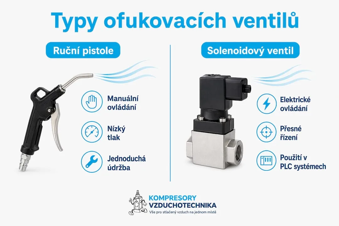
Manual guns, such as the SAM models with a working pressure of 6.2 bar and a safety air strainer, are suitable for service workshops, car repair shops, and workshops. Solenoid valves are essential wherever pneumatic actuator movement needs to be controlled automatically, without an operator present.
Advantages of solenoid valves in automation:
- Precise and repeatable switching independent of the operator
- Integration into PLC control systems and industrial automation
- Possibility of remote control and diagnostics
- Choice of neutral position for safe behaviour in case of power failure
- Lower air consumption thanks to controlled flow
Guns with a long nozzle allow cleaning of narrow and hard-to-reach places at pressures up to 6 bar. This variant is standard in the automotive industry and engineering workshops, where cavities and channels need to be cleaned without disassembly.
How to select and correctly integrate a blow gun valve?
Correct valve selection begins with defining the application. The technician must know three basic parameters: the required working pressure, the required air flow, and the method of control. Only based on these values can the correct type and configuration be chosen.
Criteria for valve selection:
- Working pressure: The valve must handle the maximum pressure in the system with a reserve. Operating at the limit of the nominal pressure shortens the lifespan of the seals.
- Flow rate (Kv value): Too small a flow coefficient causes a pressure drop. An oversized valve unnecessarily increases costs and can cause surges in the circuit.
- Port and position configuration: For simple switching, 3/2 is sufficient, for bidirectional actuators 5/2, for applications requiring defined behavior during power loss 5/3.
- Neutral position for 5/3 valves: The choice of neutral position affects operational safety and energy consumption. This decision must be part of the circuit design, not an afterthought.
- Medium and air quality: Valves for lubricated air cannot be used in systems without lubrication and vice versa. The manufacturer's specification is binding.
- Mounting position: A series of valves requires a specific orientation for proper function. Horizontal mounting where the manufacturer specifies vertical leads to failures.
Technical consultation is key when selecting a valve for non-standard applications. The balance between tightness, flow resistance, control, and cost is not always evident from catalog sheets. An experienced technician or supplier can identify hidden design risks before they manifest as a failure in operation.
Valve installation must respect the flow direction marked on the body. Swapping the inlet and outlet ports causes malfunction or damage to the valve. After installation, a functional test at operating pressure must be performed and the tightness of all connections checked.
Professional tip: When integrating a solenoid valve into a PLC system, always verify the coil supply voltage and the output type of the control system. Swapping the voltage or using an incorrect output module causes immediate damage to the coil.
The efficiency of a pneumatic system depends on the entire chain of components, from the compressor through the air receiver and air treatment to valves and actuators. The valve is only one link. An undersized piping system or insufficient air treatment will devalue even a correctly selected valve.
Key findings
A blow valve operates reliably only when it matches the application, is correctly installed, and is supplied with clean air at the appropriate pressure.
| Point | Details |
|---|---|
| Definition and types | A blow gun includes both manual guns and solenoid valves; the choice depends on the application and the required precision. |
| 3/2, 5/2, 5/3 configurations | The number of ports and positions determines the valve's function in the circuit; 5/3 additionally defines behaviour in the event of a power failure. |
| Neutral position | An incorrect choice of neutral position in a 5/3 valve causes safety risks and uncontrolled actuator movement. |
| Air quality | Moisture and contaminants are the main cause of premature valve failure; a filter upstream of the valve is a necessity. |
| Selection and consultation | Correct valve selection requires knowledge of pressure, flow and application; technical consultation reduces the risk of an incorrect choice. |
Practical experience: what technicians overlook
Zdeněk, pneumatic systems technician
Over the years of working with pneumatic circuits, I've found that the biggest problems are not caused by faulty valves, but by poor decisions made during design. The most frequently overlooked parameter is the neutral position of a 5/3-way valve. Technicians select it based on what they have in stock, not on what the application requires. The result is an actuator that either moves uncontrollably in the event of a power failure or, conversely, remains locked in a position where it should release pressure.
The second recurring problem is air quality. I have seen installations where a new valve failed within three months because there was no filter installed upstream. The valve's datasheet specifies requirements for media cleanliness, but hardly anyone reads them before installation. Yet a filter with a condensate separator costs a fraction of the valve's price and extends its service life several times over.
I recommend that every technician start the circuit design process from the end: what should happen in the event of a power failure? This question determines the choice of neutral position, and thus the type of valve. Only then does it make sense to address flow, pressure, and the method of installation. Approaching it in the opposite direction leads to a redesign or, in the worst case, to a failure on the production line.
Multi-way valves are a standard in industry, but their correct function in systems depends on details that are not listed in catalogues. Consulting with a supplier before purchase is an investment, not a waste of time.
— Zdeněk
Blow Guns and Pneumatic Accessories at Kompresory-vzduchotechnika
Kompresory-vzduchotechnika offers a complete range of products for pneumatic systems, from blow guns and solenoid valves to piping, air treatment, and compressors. Technicians will find products here for service workshops as well as for industrial automation, including technical support in selecting the right solution.
For manual applications, blow guns and spray guns for working with compressed air are available. Pneumatic piping can be supplemented with compressed air tubing of the push-in system in diameters of 15–28 mm. Air treatment upstream of valves is ensured by air treatment units for classic applications up to 10 bar. The Kompresory-vzduchotechnika team provides technical advice on selecting valves, components, and complete pneumatic assemblies.
Frequently Asked Questions
What is a blow valve in pneumatics?
A blow valve is a device for controlling the flow, pressure, and direction of compressed air. This includes manual blow guns as well as automated solenoid valves for industrial applications.
How does a solenoid blow valve work?
The solenoid valve receives an electrical signal from the PLC and mechanically switches the air flow between the ports. It enables precise and repeatable air dosing without manual operation.
What is the difference between a 5/2-way valve and a 5/3-way valve?
A 5/2-way valve has two working positions and is used for bidirectional actuators. A 5/3-way valve adds a neutral position, which defines the actuator's behavior in case of power or signal failure.
What are the most common causes of blow-off valve failures?
The main causes are contaminated air with moisture and solid particles, seal wear, incorrect installation orientation, and incorrect selection of the neutral position on 5/3 valves.
Where to buy a blow valve for industrial use?
Blow valves and complete pneumatic accessories are offered by Kompresory-vzduchotechnika, a specialized supplier with technical support for selecting the right solution for a specific application.
Recommended
- The importance of multi-way valves in industrial systems - Kompresory-Vzduchotechnika.cz
- What is an isolation valve and how to use it correctly - Kompresory-Vzduchotechnika.cz
- The check valve in compressors: technical function and application - Kompresory-Vzduchotechnika.cz
- Why use safety valves in industry and construction - Kompresory-Vzduchotechnika.cz