

Parallel compressor control maintains the required pressure at the lowest possible energy consumption. The preferred solution is a master intelligent control system with unit rotation and control based on actual consumption.
Immediate steps:
- Check the pressure band settings on each control unit and verify that the bands do not overlap or conflict.
- Verify the minimum run times (typically 3–5 minutes) and whether the rotation logic is active.
- Check the communication status between the units: a missing data connection means the compressors operate independently without coordination.
Professional tip: If the station lacks a data bus or predictive diagnostics, contact a specialist for an energy audit before making any changes to the settings.
Key takeaways
| Point | Details |
|---|---|
| Pressure band as the basis | Every unnecessary bar of overpressure increases consumption by 6–8%; set the setpoint to the minimum covering the technology. |
| Rotation is mandatory | Without active rotation, one compressor bears a disproportionate load and service intervals become shorter. |
| Communication as a prerequisite | Without a data bus (MODBUS, Profinet), predictive supervisory control cannot be deployed. |
| Pre-deployment audit | Measuring the baseline state for one week is essential for evaluating the benefits after implementation. |
| Kompresory-vzduchotechnika | Offers audits, component supply, control system integration, and 24/7 service for parallel stations. |
Contents
- How do the individual compressor control modes differ?
- What methods of parallel compressor control exist?
- What components and protocols do you need for reliable integration?
- How to correctly design and commission a parallel station?
- What metrics and alarms should be monitored at a parallel station?
- What are the most common mistakes in parallel control and how to fix them?
- What savings and operational benefits does parallel control bring?
- When is simple control sufficient and when is it worth investing in a master control system?
- Kompresory-vzduchotechnika offers design and service of parallel control
- Recommended technical resources for further reading
- Frequently asked questions
How do the individual compressor control modes differ?
The selection of the correct control mode depends on the compressed air consumption profile and the acceptable pressure band. Each mode has a different impact on energy consumption and pressure stability.
| Control mode | Principle | Suitable for | Impact on energy |
|---|---|---|---|
| Start/stop | The compressor starts and stops based on pressure | Small operations, low cycling frequency | High wear with frequent switching |
| Load/unload | The compressor runs unloaded at low demand | Medium-sized operations with fluctuating demand | Unloaded running consumes a significant portion of the rated power input |
| Modulation (by-pass) | Throttling the discharge to regulate flow | Operations with continuously varying demand | Lower efficiency at partial load |
| VSD (variable speed drive) | Frequency inverter adapts speed to demand | Operations with significant load fluctuation | Highest efficiency under variable load |
| Master network control | Central unit coordinates multiple compressors | Stations with two or more units | Lowest total consumption with correct setup |
A multi-compressor configuration equipped with VSD provides lower specific energy consumption and better pressure stability than mixed systems combining VSD with fixed-speed units. Switching to multiple VSD units reduces the control gap and keeps pressure within a narrower band, which directly reduces overall operating costs.
What methods of parallel compressor control exist?
Parallel operation of multiple compressors requires coordination logic. Four basic approaches differ in complexity, cost, and achieved efficiency.
Master/slave: One compressor (master) controls the pressure and sends commands to subordinate units (slave). Suitable for simple installations with two to three compressors and limited communication infrastructure. Drawback: the master carries a disproportionate share of operating hours unless supplemented by rotation.
Load sharing and rotation: The control logic allocates load according to the current operating hours of each unit. The compressor with the lowest number of hours is given priority for the next start. The result is even wear and extended service intervals across the entire station.
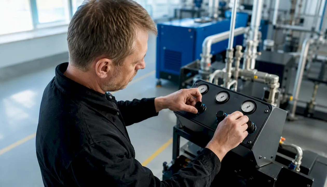
Cascade control: Units start sequentially according to fixed pressure thresholds. Simple to set up, but less efficient: when pressure drops, a second compressor starts at full output, causing transient pressure surges and unnecessary idle running.
Predictive master control (demand-based control): A central unit monitors the pressure at the point of consumption as the primary input and optimizes machine operation based on actual demand. Systems such as ARCHON from ARDAT Systems or GD Connect 12 can control up to 12 compressors from different manufacturers via a data bus. This method achieves the narrowest pressure band and the lowest overall consumption.
- Place pressure sensors as close as possible to the point of consumption, not just at the compressor discharge.
- Set the control point (setpoint) to the lowest acceptable pressure in the process, not the maximum.
- With cascade control, set the pressure thresholds with a sufficient margin (at least 0.3–0.5 bar) between units.
What components and protocols do you need for reliable integration?
Reliable parallel control requires specific hardware and data infrastructure. A missing link in the chain typically causes pressure instability or uncontrolled starts.
Mandatory components:
- A control unit (PLC or a dedicated compressor station HMI) with a sufficient number of digital and analog inputs/outputs for all units.
- Pressure sensors at the point of consumption (4–20 mA or digital output) and at the discharge of each compressor.
- Flow sensors for measuring actual air consumption (basis for predictive control).
- Variable speed drives (VSD) on units intended for continuous regulation.
- Air receiver with sufficient volume to dampen pressure peaks and transient conditions.
- Dryers and filters integrated into the control logic: their status (differential pressure across filters) must be monitored centrally.
Communication protocols and data bus:
- MODBUS RTU or MODBUS TCP/IP: the most widespread protocol for industrial compressors, supported by most manufacturers.
- Profinet or Profibus: suitable for integration into existing industrial networks based on Siemens.
- RS485: physical layer for MODBUS RTU, low-cost and reliable for distances up to 1,200 m.
Central control with a data bus enables remote diagnostics, predictive trend analysis, and reduced downtime. Without a data connection, master control is limited to analog signals, which makes predictive functions impossible.
Installation checklist:
- Verify the number of I/O points of the control unit against the number of connected compressors and sensors.
- Ensure backup power (UPS) for the control unit and communication infrastructure.
- Set up the watchdog function: in the event of a communication failure, each compressor switches to autonomous load/unload mode.
- Test the isolation of each unit without affecting the rest of the station.
How to correctly design and commission a parallel station?
The design parameters and commissioning procedure directly determine whether the station achieves the projected savings or generates unnecessary costs. Detailed requirements for the design of the compressor room, distribution, and safety are described in the guide to the basic requirements for a compressor room.
- Determine the pressure band. Every bar of unnecessary overpressure increases energy consumption by approximately 6–8 %. Set the maximum pressure to the lowest value that covers all consumption points with a reserve.
- Set the minimum run times. Typically 3–5 minutes for screw compressors. Shorter times cause excessive wear of starting components and shorten oil lifespan.
- Define priority and rotation. Assign a priority to each unit (1 = base load, 2 = peak coverage) and activate automatic rotation based on operating hours.
- Size the receiver. The air tank volume must dampen transient conditions during the start/stop of the peak unit. An undersized receiver causes frequent cycling and unstable pressure.
- Perform commissioning tests:
- Pressure stability test: simulate maximum consumption and verify that the pressure does not drop below the minimum acceptable value.
- Transient test: disconnect one unit and monitor the time it takes for the remaining compressors to cover the demand.
- Alarm verification: simulate a communication failure and check whether each unit switches to backup mode.
- Rotation test: verify that an actual priority change occurs after the set operating interval has elapsed.
Professional tip: During initial start-up, record the pressure profile and power consumption of each unit for at least 24 hours. This data serves as the baseline for later optimization and energy audits.
Which metrics and alarms should be monitored on a parallel station?
Properly configured monitoring will reveal inefficiency before it manifests as a fault or outage. Practical diagnostic procedures and KPI setup are described in detail in the article on compressor diagnostics for efficient operation.
Key metrics:
- Pressure at the point of use (bar): the primary indicator of control quality.
- Differential pressure across filters and dryers: indicates clogging and the need for replacement.
- Power consumption of each unit (kW) and specific energy consumption (kWh/m³).
- Operating hours and number of start/stop cycles for each compressor.
- Air flow (m³/min or m³/h): the basis for calculating specific consumption.
Typical alarms and their interpretation:
- Frequent starts (more than 6 per hour): pressure band too narrow or insufficient receiver capacity.
- Different power consumption at the same setting: unbalanced load, incorrect priority, or mechanical fault.
- Communication failure: the compressor switched to autonomous mode, the master control is not functioning.
- High differential pressure on the filter: clogging, replacement required before further measurement of consumption.
Recommended KPIs for an energy audit:
- Specific energy consumption (kWh/m³ of compressed air).
- Share of idle running in total operating hours (target: below 10%).
- Average pressure at the point of consumption vs. the set setpoint (deviation up to ±0.1 bar).
Professional tip: Export data from the control unit to a spreadsheet or SCADA system at least once a week. The trend of power consumption at the same flow rate is the fastest indicator of deteriorating condition.
What are the most common errors in parallel control and how to fix them?
Practical operating experience shows that most problems in parallel compressor connections stem from incorrect settings, not from hardware faults.
- Overlapping pressure thresholds: Two compressors have the same or too closely set switching pressures. Result: both try to regulate at the same time, pressure oscillates. Fix: set the thresholds with a gap of at least 0.3 bar.
- Missing rotation: One compressor carries the entire base load, the other stands idle. Operating hours accumulate unevenly, service intervals are shortened on one unit. Fix: activate automatic rotation in the control unit.
- Incorrect priority: The more powerful unit is set as backup instead of the base unit. Fix: assign priority 1 to the unit with the lowest operating cost per m³.
- Loss of communication without backup: If the bus fails, the master control stops functioning and the compressors behave uncontrollably. Fix: set up a watchdog and a backup autonomous load/unload mode for each unit.
- Insufficient receiver: Pressure fluctuates with every start of the peak unit. Fix: increase the air receiver volume or slow down the control logic response by extending the minimum run time.
During basic diagnostics before calling service, check in this order: the pressure profile over the last 24 hours, the number of start/stop cycles, communication status, and the power input of each unit at the same demand.
What savings and operational benefits does parallel control provide?
A properly deployed master intelligent control system delivers measurable results. This result stems from a combination of three effects: maintaining pressure within a narrower band, eliminating idle running, and evenly distributing the load.
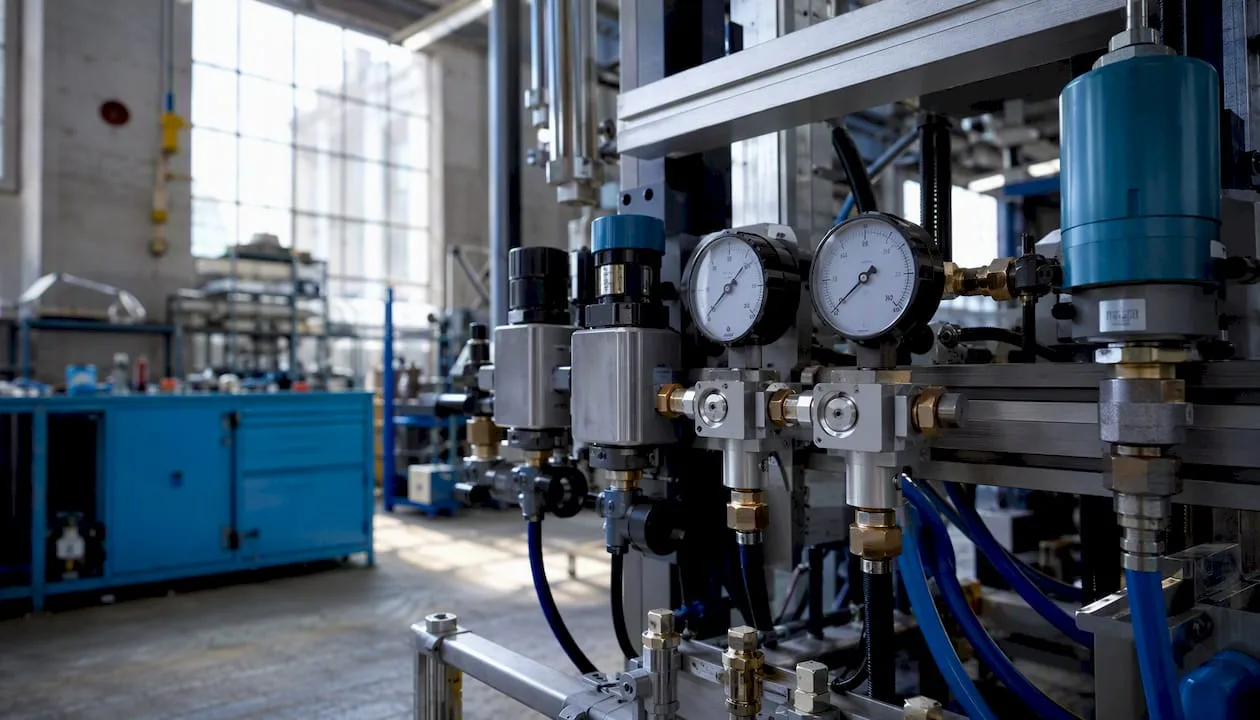
The greatest benefit of master control is not only energy savings, but also extended service intervals thanks to intelligent rotation and even distribution of operating hours. Integrating dryers, oil separators, and flow meters into the control logic enables full automation and efficient unattended operation, as confirmed by references from completed installations.
Recommended steps to maximize the benefit:
- Before deploying master control, measure the baseline state (power input, flow, pressure) for at least one week.
- Keep historical data for before/after implementation comparison.
- Tune the settings gradually: first the pressure band, then rotation, and finally predictive functions.
- Include dryers and filters in the control logic for full automation of air quality. Suitable compressed air treatment units are available for various flow rates and pressure classes.
Detailed techniques for calculating payback and energy audits are described in the expert guide to energy savings with a compressor.
When is simple control sufficient and when is it worth investing in a supervisory system?
The decision depends on four variables: consumption fluctuation, number of units, operating hours, and energy price.
Simple cascade or master/slave control is sufficient for stations with two compressors, stable consumption, and operation of less than 2,000 hours per year. In such cases, the cost of a supervisory system will not pay back within a reasonable time horizon.
Recommended procedure: energy audit as the first step, pilot deployment at one station, evaluation of data after three months, then decision on full deployment.
Kompresory-vzduchotechnika offers design and service of parallel control
Kompresory-vzduchotechnika provides a complete supply for parallel stations: from the selection and supply of SCR screw compressors, through the design of control logic, to commissioning and 24/7 service. The cooperation takes place in four phases: audit of the current state and consumption measurement, configuration design and component selection, installation and integration of control systems, commissioning and handover with a protocol.
For operations lacking data connectivity or predictive diagnostics, Kompresory-vzduchotechnika offers a free consultation and on-site pressure and consumption measurement. Contact the technical team via Kompresory-vzduchotechnika and arrange an audit date.
Recommended technical resources for further reading
- Technical datasheets from control system manufacturers — (ARDAT Systems ARCHON, GD Connect 12): include I/O specifications, supported protocols, and configuration examples for different numbers of units.
- Atlas Copco technical documentation on VSD configuration — analysis of the benefits of multiple VSD units over mixed systems in terms of specific energy consumption and pressure stability.
Frequently asked questions
What is parallel compressor control and how does it work?
Parallel compressor control coordinates the operation of two or more compressors so that they jointly maintain the required pressure with minimal energy consumption. The central control unit allocates load to individual compressors based on current demand and operating hours.
What energy savings are realistic with master control?
The specific result depends on the demand profile, the pressure band setting, and the number of units.
Which communication protocol is most commonly used for controlling multiple compressors?
MODBUS RTU or MODBUS TCP/IP is the most widespread protocol for industrial compressors and is supported by most manufacturers. For integration into Siemens networks, Profinet or Profibus is used.
From how many compressors does it pay off to implement master control?
Master control is economically justified with a larger number of units or a higher number of operating hours with significant fluctuation in demand. For two units with stable demand, cascade or master/slave control is usually sufficient.
What causes unstable pressure during parallel operation?
The most common causes are overlapping pressure thresholds of the units, insufficient air tank volume, or a communication failure between the compressors. Basic diagnostics include checking the pressure trend over the last 24 hours and the number of start/stop cycles.
Recommended
- List of the best compressors 2026: a buying guide - Kompresory-Vzduchotechnika.cz
- Basic requirements for a compressor room: guide 2026 - Kompresory-Vzduchotechnika.cz
- Definition of the compressor duty cycle: a guide for technicians - Kompresory-Vzduchotechnika.cz
- Factors for selecting an industrial compressor: a 2026 guide - Kompresory-Vzduchotechnika.cz