

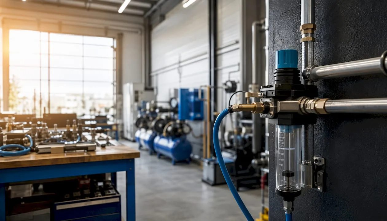
A flow meter in a pneumatic system performs one essential function: it verifies that the system is actually delivering the volume of compressed air that actuators and processes require. Without this measurement, you are operating the system blindly. Insufficient flow reduces pressure directly at the point of use, slows cylinder movement, and reduces their force. Conversely, excess flow without measurement means unnecessary energy costs. Install the flow meter first on the main supply line and on branches to production machines, where you will identify the largest losses.
- Consumption diagnostics: monitoring actual consumption per machine or line
- Leak detection: comparing flow in idle and operating modes reveals air leaks
- Verification of actuator performance: checking whether cylinders receive the required flow for correct speed and force
A flow meter is not just a measuring instrument. It is a diagnostic tool that determines whether your pneumatic system is operating as designed, or only approximately.
Professional tip: When first deploying a flow meter, measure consumption in idle state (without production). Any non-zero flow indicates leaks, which directly increase compressor costs.
Contents
- Why measure compressed air flow?
- What principles and types of flow meters are suitable for pneumatics?
- How to choose a flow meter for compressed air?
- How to correctly install a flow meter in a pneumatic distribution system?
- How to calibrate and maintain a flow meter?
- Practical applications and calculation examples
- Available technologies and support for the Czech market
- Key Takeaways
- Flow meter as the first step of an energy audit
- Kompresory-vzduchotechnika: measurement, design and service in one place
- Selected sources and further reading
- FAQ
Why measure compressed air flow?
Flow measurement delivers concrete operational and economic results. Without data on actual consumption, it is not possible to effectively manage compressed air energy use or plan compressor capacity.
- Energy savings: identifying losses and optimizing operating cycles reduces compressor power input; compressed air consumption optimization starts precisely with measurement
- Leak quantification: continuous measurement on main branches with comparative analysis of idle and operating flow reliably detects and quantifies leaks
- Verification of actuator performance: the correct speed and force of cylinders depends on the delivered flow, not just the set pressure
- Energy audits and reporting: the flow meter provides data for monitoring consumption by department, machine, or product, which is essential for both internal and external audits
- Return on investment calculation: measuring consumption before and after optimization gives an accurate figure for savings; a typical example is packaging lines, where isolated measurement of each station reveals which one consumes disproportionately
The relationship between flow and actuator performance is direct. If a cylinder does not receive sufficient flow, movement slows down or force drops below the required value. A pressure gauge will not detect this situation, because the pressure at the supply may be fine while the flow is restricted by a bottleneck in the piping.
What principles and types of flow meters are suitable for pneumatics?
Several measurement principles are applicable to compressed air. Each has different strengths and different limitations.
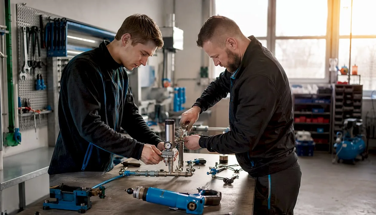
Thermal (calorimetric) mass flow meters operate on the principle of a heated sensor: the probe measures the heat loss from the heated element caused by the flowing gas. The result is directly in mass or normalized units (Nm³/h) without the need to convert to current pressure and temperature. For this reason, they are the most commonly preferred choice for compressed air, especially for low flows and applications with variable pressure.
Differential pressure flow meters (orifice plates, nozzles, Venturi tubes) are among the most widespread in industry. They are robust and proven, but require precise installation, since turbulence significantly affects accuracy. The result depends on pressure and temperature, so conversion to normalized conditions is necessary.
Turbine and vane flow meters are sensitive to the cleanliness of the medium. Condensate or oil in the piping quickly damages the rotating parts. They require straight sections of piping before and after the meter.
Ultrasonic flow meters enable non-invasive measurement from outside the pipe without interrupting operation. They minimize pressure losses and are suitable where intervention in the piping is not possible.
Coriolis flow meters measure mass flow and density with high accuracy, independent of pressure, temperature, and viscosity. However, they are more expensive and are used where accuracy directly affects the process or billing.
Electromagnetic (inductive) flow meters are intended exclusively for electrically conductive liquids, and are therefore not suitable for compressed air.
| Principle | Advantages | Disadvantages | Typical Application |
|---|---|---|---|
| Thermal Mass | Independence from PT, direct Nm³/h, low flow rates | Sensitivity to oil and condensate | Main distribution lines, leak detection |
| Differential Pressure | Robust, proven, low cost | Dependence on PT, need for recalculations | Industrial distribution lines, high flow rates |
| Turbine | Good accuracy, fast response | Sensitive to contaminants, straight pipe sections required | Clean air, medium flow rates |
| Ultrasonic | Non-invasive, no pressure loss | Higher cost, affected by flow profile | Retrofit, no need to cut into the piping |
| Coriolis | Highest accuracy, mass measurement | High cost, larger dimensions | Critical processes, billing |

Professional tip: If the distribution system contains condensate or traces of oil, prefer a thermal mass flow meter with an upstream oil and condensate separator. Turbine and vane types deteriorate quickly in such an environment.
How to choose a flow meter for compressed air?
Selecting a flow meter depends on a combination of operating parameters. No single criterion is sufficient.
Key selection criteria:
- Measurement range (rangeability): the ratio of maximum to minimum measurable flow; for systems with variable consumption, choose a flow meter with a rangeability of at least 10:1
- Accuracy and repeatability: ±2–3% is sufficient for energy audits, while ±0.5–1% is required for billing or critical processes
- Pressure drop: differential pressure types cause a higher pressure drop than ultrasonic or thermal types
- Resistance to contaminants: oil and condensate will damage turbine types; thermal sensors require clean air or upstream filtration
- Operating pressure and temperature: verify that the device covers the entire range of operating conditions
- Materials and connections: threaded or flanged connection, body and seal materials must match the operating medium
- Certification and calibration traceability: for audits and metrology requirements, require a calibration certificate traceable to a national standard
The effect of pressure and temperature on measurement is critical for volumetric flow meters. The flow measured at an operating pressure of 7 bar differs significantly from the value at atmospheric pressure. Thermal mass flow meters perform this conversion automatically. For other types, the measured value must be converted to normal conditions (Nm³/h at 0 °C and 101.325 kPa) or temperature and pressure compensation must be used.
Example flow calculation for a cylinder:
- Failure to observe these sections causes turbulence, which leads to non-linear measurement and percent-level errors.
- Add the volume for the return stroke (smaller piston area due to the rod)
- Multiply by the cycle frequency: 20 cycles/min × 0.624 l = 12.5 l/min at operating pressure
- Convert to normalized conditions: at 7 bar (abs) ≈ 87.5 Nl/min = 5.25 Nm³/h
This calculation determines the minimum flow rate that the flow meter must reliably measure. Add a reserve for other consumers on the branch.
The flow coefficient Cv of valves directly affects how much air can pass through the control valve. An undersized valve creates a bottleneck that cannot be compensated for by higher compressor pressure. Cv must be recalculated for compressible gas, not just for liquids. A flow meter placed downstream of the valve reveals whether the valve actually allows the required flow rate to pass. More about the relationship between valves and flow can be found in a separate article.
How to properly install a flow meter in a pneumatic distribution system?
Installation determines the accuracy of measurement just as much as the quality of the device itself. In practice, installation errors are a more common cause of deviations than sensor errors.
Requirements for straight sections:
- Turbine and vane flow meters: at least 10× the pipe diameter upstream of the meter and 5× downstream
- Thermal mass flow meters: typically 5–10× the diameter upstream, 3–5× downstream (depending on manufacturer)
- Differential pressure types: 20× the diameter upstream and 5× downstream for orifice plates; less for Venturi tubes
Failure to observe these sections causes turbulence, which leads to non-linear measurement and errors of a percentage order.
Installation procedure:
- Plan the piping route and verify the availability of the required straight sections
- Install a filter upstream, a condensate separator and an oil separator immediately before the meter
- Install the flow meter in the correct orientation (horizontally or vertically according to the manufacturer's specification)
- Check the seals and tightness of connections; use seals compatible with the pressure medium
- Install simultaneous pressure and temperature measurement if the flow meter does not perform compensation automatically
- Set up a bypass or shut-off valves to allow replacement without shutting down the line
- Verify zero flow with the system closed (zero point check)
Placement recommendations: the main supply line will capture total consumption, branching to individual machines will allow leak localization, measurement close to the consumer will verify the performance of a specific drive.
Professional tip: Design a bypass with shut-off valves on both sides of the flow meter. This way, you won't need to shut down the entire line during calibration or sensor replacement. This small investment in installation will save hours of downtime at every maintenance.
How to calibrate and maintain a flow meter?
Flow meter accuracy changes over time. Regular calibration and maintenance are a prerequisite for data usable in energy audits.
Recommended intervals and procedures:
- Initial check after installation: verify the zero point and compare with a reference meter or a known volume
- Annual calibration for critical applications: for flow meters used in energy reporting or billing; for less critical applications, calibration every two years is sufficient
- Drift monitoring: regular comparison with a portable reference meter or with pressure test results will reveal drift before it causes data errors
- Sensor cleaning: thermal sensors are sensitive to oil deposits; clean according to the manufacturer's recommendations, usually at each annual inspection
- Seal inspection: at each inspection, check the tightness of joints and the condition of seals
Flow meters in industrial facilities fulfil three main roles: consumption measurement, leak detection, and verification of actuator performance.
- OK Zbytek:
- Open to a control flow rate and compare with a reference instrument or a calculated value
- Record the result in the instrument's log card
A calibration audit trail is a mandatory document for energy audits under ČSN EN ISO 50001. Without it, the credibility of the measured data cannot be demonstrated.
Practical applications and calculation examples
Flow meters in industrial facilities fulfil three main roles: consumption measurement, leak detection, and verification of drive performance.
Measuring consumption of a machine line: a flow meter on the line's supply records total consumption in Nm³/cycle or Nm³/h. Comparison with the projected value reveals whether the line is operating efficiently or whether consumption has changed (seal wear, process change).
Leak detection on a branched distribution system: flow meters on the main branch and on the outputs to individual sections enable balance measurement. The difference between inflow and the sum of outflows corresponds to the leak. Measurement in idle state (without production) then directly quantifies leaks.
Sample calculation of savings from eliminating a leak:
- Measured flow in idle state: 15 Nm³/h
- Operating pressure: 7 bar, compressor power input: approximately 0.1 kWh/Nm³
- Annual loss: 15 Nm³/h × 8,000 h × 0.1 kWh/Nm³ = 12,000 kWh/year
- At an electricity price of CZK 4/kWh: CZK 48,000/year on leaks alone
Data interpretation: flow peaks during machine start-up are normal. An anomaly occurs if the idle-state flow does not drop to zero, or if the peaks exceed the projected value. Both indicate either leaks or an undersized distribution system.
Recommended reporting metrics: Nm³/h (instantaneous flow), Nm³/cycle (consumption per production cycle), specific consumption per product (Nm³/pc).
Warning: condensate or oil in the piping will cause incorrect results with both thermal sensors (deposits on the probe) and turbine types (mechanical damage). Diagnostics: if the flow meter shows nonzero flow with the system closed, or significantly fluctuating values with no apparent cause, check the upstream filtration and the sensor's condition.
Available technologies and support for the Czech market
All major flow meter technologies for compressed air are available on the Czech market: thermal mass, differential pressure, turbine, and ultrasonic. For industrial applications in the Czech Republic, thermal mass flow meters are most commonly deployed for distribution lines, and differential pressure types for larger pipe diameters.
- Thermal mass flow meters: available from a range of suppliers, suitable for the DN15–DN100 range, typical operating pressures up to 16 bar
- Ultrasonic types: suitable for retrofitting existing distribution systems without the need to intervene in the piping
- Differential pressure types: standard solution for larger diameters and high flow rates
Kompresory-vzduchotechnika offers complete support from flow meter selection through installation design to calibration and service. Services include consumption measurement and reporting, turnkey solution design, equipment supply, installation, calibration, and 24/7 service. For a pilot measurement, we recommend starting with a single flow meter on the main supply line or on the most problematic branch.
Professional tip: Before requesting a quote, prepare a distribution diagram with marked pipe diameters, operating pressures, and required measurement points. Add the required accuracy and goals (leak detection, energy audit, performance verification). With this documentation, you will receive a specific offer instead of a general catalog.
Key findings
A flow meter in a pneumatic system is an essential tool for diagnosing consumption, detecting leaks, and verifying actuator performance, with the correct choice of technology and installation directly determining the reliability of the measured data.
| Point | Details |
|---|---|
| Main role of the flow meter | Consumption diagnostics, leak detection, and flow verification for actuators are three key functions. |
| Technology selection | For compressed air, thermal mass flow meters are the most commonly preferred choice due to their independence from pressure and temperature. |
| Installation and straight sections | Turbine types require 10× diameter upstream and 5× downstream of the meter; failure to comply causes errors on the order of a few percent. |
| Calibration and audit | Annual calibration with an audit trail is a prerequisite for data usable in energy audits according to ČSN EN ISO 50001. |
| Compressors-air technology | It offers selection, supply, installation and calibration of flow meters, including energy audits and non-stop service. |
Flow meter as the first step of an energy audit
Flow meters tend to be underestimated in practice. Technicians address pressure, compressor output, and filter condition, but they only measure flow once the problem has fully manifested. This is a mistake that makes operation more expensive.
The most common mistake that recurs in operation: installing the flow meter in the wrong location without upstream filtration. The sensor becomes clogged with oil or condensate, the data becomes unreliable, and the technician concludes that the flow meter "doesn't work." However, the problem is not with the device, but with the installation. The correct order is always: filtration, condensate separator, oil separator, and only then the flow meter.
A second recurring problem is the failure to maintain straight pipe runs. Piping in industrial facilities is often routed with regard to available space, not metrology. An elbow positioned just before the meter causes turbulence that distorts the reading. Planning the pipe route with regard to the flow meter's installation requirements must take place at the design stage, not during installation.
Recommendation for technicians: start with a single flow meter on the main supply line, measure the baseline flow, and compare it to the designed value. The result of the first measurement will almost always reveal either leaks or an undersized distribution system. Only based on this data should you decide on further expansion of the measurement infrastructure.
Kompresory-vzduchotechnika: measurement, design, and service in one place
If you want to actually measure the flow of compressed air rather than just estimate it, Kompresory-vzduchotechnika offers a direct path from device selection to commissioning and calibration.
Services include consumption measurement and report processing, design of measurement points according to the distribution scheme, supply of flow meters for all common diameters and pressures, installation in compliance with installation requirements, calibration with certificate issuance, and 24/7 service. For energy audits, we provide a complete measurement campaign including documentation.
A pilot measurement can be ordered as a standalone service: we bring a portable flow meter, measure consumption at selected points, and provide a report with recommendations. The complete range of flow meters and accessories for pneumatic systems is available online. For consultation on selection or to order a pilot measurement, contact the technical department of Kompresory-vzduchotechnika directly via the website.
Selected sources and further reading
For deeper study and verification of technical parameters, we recommend the following sources:
- ČSN EN ISO 5167 (measurement of fluid flow by differential pressure devices): normative basis for orifice plates, nozzles, and Venturi tubes
- ČSN EN ISO 50001 (energy management systems): requirements for measuring and recording energy consumption, including compressed air
- TZB-info, Industrial Technology section: overview articles on flow meter principles and installation requirements
- How to choose an air flow meter on Kompresory-vzduchotechnika.cz: a technical comparison of technologies with practical recommendations
- Methods for Testing Air Flow: a guide to measurement techniques for technicians
- Procedure for Solving Air Leaks: step by step from detection to correction
When preparing an inquiry or a pilot measurement, we recommend first studying the normative requirements of ČSN EN ISO 50001 for measuring points and accuracy, and then consulting the choice of technology with the supplier based on the specific distribution scheme.
Frequently asked questions
How does a flow meter work in compressed air?
A flow meter measures the volume or mass of air passing through a pipe per unit of time. The principle depends on the technology: a thermal sensor measures the cooling of a heated element, a differential pressure type measures the pressure drop across a primary element, and a turbine type counts the rotor revolutions.
How does a mass flow meter work?
A thermal mass flow meter heats a sensor element and measures how much heat the flowing gas removes. A higher flow rate causes greater cooling. The result is given directly in mass or normalized units (Nm³/h) without dependence on the current pressure and temperature.
How does an inductive (electromagnetic) flow meter work?
An electromagnetic flow meter measures the flow of electrically conductive liquids based on Faraday's law of electromagnetic induction. It is not suitable for compressed air, because air is not electrically conductive.
Which type of flow meter is best for leak detection?
Thermal mass flow meters are the most suitable for leak detection: they measure directly in Nm³/h without conversions, have good sensitivity at low flow rates, and allow continuous monitoring with comparative analysis of idle and operating states.
How often does a flow meter need to be calibrated?
For flow meters used in energy reporting or audits, annual calibration with issuance of a certificate traceable to a national standard is recommended. For less critical applications, calibration every two years is sufficient, supplemented by ongoing drift monitoring using a portable reference meter.
Recommended
- Pneumatic systems explained: a guide for technicians - Kompresory-Vzduchotechnika.cz
- What is pneumatic lubrication: a guide for technicians - Kompresory-Vzduchotechnika.cz
- Why use pneumatics: efficiency, speed and safety - Kompresory-Vzduchotechnika.cz
- How pneumatics works: a complete guide for industry 2026