
TL;DR:
- Pneumatic cylinders can bounce back once they reach the end position because air is compressible, not because a component has failed.
- Correct sizing and control of air flow are key to the reliability of the system and to eliminating bounce.
Pneumatic systems explained in practice starts with one surprising fact: a pneumatic cylinder does not necessarily come to a completely calm stop when it reaches the end position. Instead it can bounce, oscillate and only then settle. This is not a component failure. It is a direct consequence of the physics of compressed air. Understanding this behaviour and the other principles of pneumatic systems is the foundation for correct design, safe operation and the right choice of components. This article offers a technically accurate, practically oriented overview for technicians, engineers and students who want to understand pneumatics in depth.
Contents
- Key takeaways
- How pneumatic systems work and what they consist of
- Physical principles and limits of pneumatics
- Types of pneumatic actuators and choosing the right one
- Operating and maintaining pneumatic systems
- A view from practice: what textbooks do not tell you
- Pneumatic solutions from Kompresory-vzduchotechnika
- FAQ
Key takeaways
| Point | Details |
|---|---|
| Compressed air as the working medium | Air pressure and flow directly determine the force and the speed of a pneumatic actuator. |
| The physics of air compressibility | Bounce and oscillation of the cylinder are physical properties, not faults, and they can be controlled by design. |
| Calculating actuator force | Force is calculated with the formula F = P × A, while air flow determines the speed of the movement. |
| Comparison with hydraulics | Air is compressible, hydraulic fluid is not, which fundamentally affects the dynamics of the system. |
| Air preparation and filtration | Good filtration and air treatment are decisive for the service life and the reliability of the system. |
How pneumatic systems work and what they consist of
Pneumatics uses compressed air to create movement and force. The compressor compresses air to working pressure, the air tank stores it and the pressure regulator makes sure that the air entering the system has the right parameters. From there the air continues through valves to the actuators, where pressure energy is converted into mechanical movement.
The basic components of a pneumatic system form a logical chain from the energy source to the working element:
- Compressor: Converts mechanical energy into the pressure energy of compressed air. Compressor output affects the maximum flow and the pressure achievable throughout the system.
- Air tank (air receiver): Evens out fluctuations in consumption, keeps the pressure stable and protects the compressor from excessive switching.
- Air preparation unit (FRL): The filter traps contaminants and condensate, the regulator sets the working pressure and the automatic lubricator adds oil to lubricate the moving parts.
- Pneumatic valves: Control the direction, flow and pressure of the air. The most common are 5/2 valves for controlling double-acting cylinders.
- Pneumatic cylinders and motors: Actuators convert the pressure energy of the air into linear or rotary movement.
Controlling air pressure and flow is key to the precise operation of pneumatic actuators and to optimising the performance of the whole system. A more detailed look at how pneumatics works in industry is offered by our guide to how pneumatics works.
Professional tip: When sizing an air tank, a general rule applies: the tank volume should be at least ten times the air consumption per minute for a duty cycle with short, repeated strokes.
Physical principles and limits of pneumatics
The key difference between pneumatics and hydraulics lies in the compressibility of the working medium. Hydraulics uses a fluid that is almost incompressible, so force is transmitted practically instantly and the movement is very stiff. Air, on the other hand, is compressible, and that fundamentally changes the dynamic behaviour of the whole system.
Compressed air inside a pneumatic cylinder acts like a spring. When the piston reaches the end position, the accumulated elastic energy of the air pushes it back. The result is a spring effect and a bounce of the piston, which can cause oscillation. This behaviour depends on the volume of air in front of and behind the piston, on the mass of the moving part and on the stiffness of the system.

| Property | Pneumatics | Hydraulics |
|---|---|---|
| Working medium | Compressed air | Hydraulic fluid |
| Compressibility of the medium | High | Practically zero |
| Dynamic stiffness | Low, springy behaviour | High, stiff behaviour |
| Positioning accuracy | Lower without position sensing | High |
| Risk of fire and leakage | Low | Higher |
| Operating costs | Lower | Higher |
| Cleanliness of operation | Clean operation | Risk of oil leakage |
Bounce of pneumatic cylinders is a natural phenomenon caused by the compressibility of air, not a fault of the components. It can be controlled by setting the end-of-stroke cushioning, by using hydraulic shock absorbers or by actively regulating air flow with a throttle valve.
The resonant frequency of a pneumatic cylinder depends on the effective stiffness of the air column and on the mass of the moving load. When designing systems with fast cycles or precise positioning, the dynamics of the air column must be taken into account already at the calculation stage.
Professional tip: If the system shows repeated cylinder oscillation when stopping, the first step is not to replace a component but to check the setting of the throttle valves and verify that the end-of-stroke cushioning matches the mass of the load.
Types of pneumatic actuators and choosing the right one
What is a pneumatic actuator and how do you choose it correctly? A pneumatic actuator is a device that converts the pressure energy of compressed air into mechanical movement. In industry, pneumatic actuators handle linear travel, rotation, clamping, pressing and sorting.
Calculating force and speed
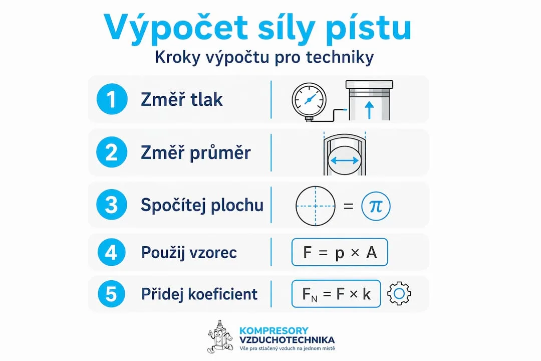
The force of a pneumatic cylinder is calculated with the formula F = P × A, where P is the working pressure in pascals and A is the effective piston area in square metres. The result is the theoretical force. In practice an efficiency of 0.8 to 0.9 is assumed because of seal friction and mechanical losses.
The travel speed depends on the air flow Q supplied to the cylinder. The performance of pneumatic cylinders depends not only on pressure and piston area, but to a large extent also on the available air flow, which directly affects the travel speed. An undersized supply valve or hose will restrict the flow and the cylinder will work slowly regardless of the pressure.
Design variants of actuators
The choice between rod and rodless cylinders depends on the stroke length and on the space available. Rodless cylinders allow strokes longer than the cylinder itself, because the load is guided alongside the cylinder body. They are compact and suitable for applications with limited space along the axis of movement.
In addition to the required force, the selection of a pneumatic actuator must take into account the load on the end of the rod. Axial loading is the ideal case. Side loads and moments shorten the service life of bearings and seals. If side loading cannot be avoided by design, a cylinder with an integrated guide must be used or a separate linear guide must be added.
A comparison of the most common design variants:
| Actuator type | Advantages | Limitations |
|---|---|---|
| Single-acting cylinder | Simple connection, low air consumption | Force in one direction only |
| Double-acting cylinder | Force in both directions, full control of movement | Higher air consumption |
| Rodless cylinder | Compact, long strokes | Requires a guide, more complex sealing |
| Rotary actuator | Rotary movement through a defined angle | Limited range of rotation |
| Air motor | Continuous rotation, variable speed | Lower efficiency than an electric drive |
Protection against unwanted rotation of the rod is provided either by a key and keyway directly on the rod or by an external guide. In precise applications where the position of the tool on the rod must not rotate, this is a design requirement, not an optional extra.
Professional tip: To choose an actuator correctly, always start from the required force and add a safety factor of at least 1.5. Then check the air flow throughout the supply line, because it is the flow that is the most common reason why an actuator does not reach the expected speed.
Operating and maintaining pneumatic systems
Reliable operation of a pneumatic system starts with air quality. Correct air preparation and filtration significantly affects the reliability and service life of pneumatic components. Condensate, oil and solid contaminants in the pipework are the most common cause of premature wear of seals and valves.
The recommended procedure for optimal operation and maintenance includes these steps:
- Checking and draining the filters: Filters that trap solid contaminants and condensate must be checked and emptied regularly. A clogged filter increases the pressure drop and reduces the performance of the whole system.
- Setting the pressure regulator: Set the working pressure to the lowest value at which the actuator reliably performs the required work. Unnecessarily high pressure increases air consumption, seal wear and noise.
- Checking the lubricator: If the system includes an automatic lubricator, check the oil level and the correct dosing setting. Too much oil contaminates the filtration, too little causes dry wear of the moving parts.
- Checking pipework for leaks: Leaks in the air distribution system can mean a loss of 20 to 30 % of the compressor output. Regular leak detection with an ultrasonic detector or with soapy water is a standard service task.
- Checking the condition of cylinder seals: If the force drops or air leaks around the cylinder rod, the seals must be replaced. A postponed repair leads to damage to the rod surface and to the need to replace the whole cylinder.
- Safety measures: Before any service work on a pneumatic system it is mandatory to vent the system, lock off the air supply and verify that the pressure has dropped to zero. Handled incorrectly, compressed air represents a serious safety risk.
Pneumatic systems are less prone to fire and leakage than hydraulic systems, which simplifies their operation in environments with fire risks or in the food industry. This operational advantage is, however, conditional on correct air preparation and regular maintenance of the filtration.
A view from practice: what textbooks do not tell you
From my own experience with pneumatic systems I know that the most common design mistakes do not come from not knowing the basic formulas, but from underestimating the physics of air in a real pipework network.
I have seen many projects where the calculation of the cylinder force was correct, but the cylinder did not work properly. The cause? An undersized supply valve or pipework that was too long and too thin to deliver the required air flow. The pressure was fine. The flow was not.
The second recurring problem is treating cylinder bounce as a fault. The designer changes the cylinder, the problem persists, because the cause lies in the physics of compressed air, not in the component. Bounce can be controlled by cushioning, design changes and the setting of the throttle valves. But first it has to be understood as a physical phenomenon.
In practice, the comparison between pneumatics and hydraulics is often reduced to "pneumatics is cheaper." That is true, but incomplete. Pneumatics is cheaper to buy and maintain, cleaner in operation and safer in environments where a leak of the medium would be risky. Hydraulics offers stiff movement, precise positioning and high forces in a small space. The choice depends on the specific application, not on a general rule.
My recommendation to everyone designing a pneumatic system: give the air distribution the same attention as the selection of the actuators themselves. The compressor, pipework, valves and filtration form a single whole. A weak link in this chain reduces the performance of the entire system regardless of the quality of the individual components.
— Zdeněk
Pneumatic solutions from Kompresory-vzduchotechnika
Kompresory-vzduchotechnika offers a complete range for the design, installation and servicing of pneumatic systems. From compressors and air tanks through air preparation units to air tools and accessories for industrial applications.
The expert team at Kompresory-vzduchotechnika provides technical advice on selecting components, sizing systems and solving operational problems. The product range includes pneumatic and hydraulic equipment for industry, construction, automotive and workshops. Professional users also have access to air tools and accessories powered by compressed air, with full technical support.
Kompresory-vzduchotechnika focuses on making sure customers get exactly the solution that matches their operating conditions and technical requirements. Consultation is available directly through the website and is provided by an experienced technical team.
FAQ
What is a pneumatic actuator and how does it work?
A pneumatic actuator is a device that converts the pressure energy of compressed air into mechanical movement. Pressurised air acts on the piston area and creates a force according to the formula F = P × A.
Why does a pneumatic cylinder bounce after reaching the end position?
Bounce is a direct consequence of the compressibility of air. The air in the cylinder acts like a spring and pushes the piston back once it reaches the end stop. It can be controlled by setting the cushioning and the throttle valves.
What is the main difference between pneumatics and hydraulics?
Pneumatics works with compressed air, which is compressible, while hydraulics uses a fluid with practically zero compressibility. As a result, hydraulic systems offer stiffer movement and more accurate positioning, while pneumatics is simpler, cleaner and safer in operation.
How is the force of a pneumatic cylinder calculated?
The force is calculated with the formula F = P × A, where P is the working pressure and A is the effective piston area. In practice the result is multiplied by an efficiency factor of 0.8 to 0.9 to allow for seal friction.
Why is air filtration in a pneumatic system so important?
Condensate, contaminants and oil in the pipework damage seals, valves and actuators. Good filtration directly determines the service life of the components and the reliability of the whole system in long-term operation.
Recommended
- What is pneumatic lubrication: a guide for technicians - Kompresory-Vzduchotechnika.cz
- How pneumatics works: a complete guide for industry 2026
- What is pneumatic automation: a guide for industry - Kompresory-Vzduchotechnika.cz
- Why use pneumatics: efficiency, speed and safety - Kompresory-Vzduchotechnika.cz