

TL;DR:
- Correct ductwork installation is the key to eliminating leaks and noise. Plan the route thoroughly in advance, choose suitable materials and carry out leak testing consistently. Balancing the system and accurate documentation ensure long-term efficiency and easy maintenance.
Installing ductwork without a clear procedure leads to leaks, excessive noise and unnecessary rework. Step-by-step duct installation requires preparation, the right choice of materials and precise execution of every joint. This ductwork installation guide covers the whole process, from planning the route through joining the parts to leak tests and balancing the system. Whether you work alone or as part of an installation team, you will find concrete steps for installing ductwork here, without unnecessary theory.
Table of contents
- Key takeaways
- Preparation and materials before installation
- Step-by-step installation process
- Technical parameters and route design
- Inspection and maintenance after installation
- From practice: what determines installation quality
- Equipment for ductwork installation
- FAQ
Key takeaways
| Point | Details |
|---|---|
| Route planning as the foundation | Design the routes before installation, taking into account crossings with other services and access to inspection openings. |
| Sizing according to airflow | For residential spaces allow for an airflow of 20 to 40 m³/h per person and an air velocity of around 4 m/s. |
| Leak test before closing up | Always carry out pressure tests before suspended ceilings are installed, otherwise repairs are expensive and time-consuming. |
| Balancing the system after installation | After installation, carry out primary balancing of the main runs and secondary balancing of the individual branches. |
| As-built documentation | Record the exact positions of the ducting and control elements for future service and repairs. |
Preparation and materials before installation
A successful ductwork installation begins long before you reach for your tools. Underestimated preparation is the cause of most problems that only show up once the installation is finished.
Duct components and materials
The basic kit for the installation includes ducting (round or rectangular), fittings (bends, branches, reducers), hangers and clamps for fixing, sealing tape and sealants, control dampers and air terminal devices. The choice of duct material depends on the specific application. Galvanised sheet is the standard for industrial installations. Flexible ducting made of aluminium or plastic is suitable for short connections and for connecting to diffusers.
Professional tip: Never use flexible hoses for the main trunk runs. They cause higher pressure losses and restrict airflow, especially at diameters above 160 mm.
| Component | Material | Typical use |
|---|---|---|
| Main run ducting | Galvanized sheet metal | Backbone ductwork |
| Connection pipes | Flexible aluminum | Connection to diffusers |
| Fittings | Galvanised sheet, plastic | Elbows, branches |
| Seals | Butyl or acrylic tape | Pipe joints |
| Hangers | Galvanized steel | Fixing to the load-bearing structure |
Tools for assembly
The basic equipment includes aviation snips or an angle grinder, a riveter, a tape measure, a spirit level and a drill with a set of drill bits and wall plugs. A file for removing sharp edges is also useful when working with galvanised sheet. For a precise connection to compressors and compressed air lines, use M7 air tools, which speed up fixing work considerably.
Planning the distribution routes
Installation in suspended ceilings requires the routes to be planned so that they do not cross other services and access to inspection hatches is maintained. Ventilation should be part of the architectural design from the very beginning, not only during the finishing works. This applies particularly to installations with suspended ceiling systems, where later changes mean dismantling entire sections.
When sizing ducting for residential rooms, allow for an airflow of 20 to 40 m³/h per person and keep the CO2 level below 1000 ppm. Choose the duct cross-section so that the air velocity does not exceed the recommended values.
Step-by-step installation process
This section describes how to assemble ductwork from preparing the first parts to the final sealing. Keeping to the order of the steps is essential.
Preparing and cutting the components
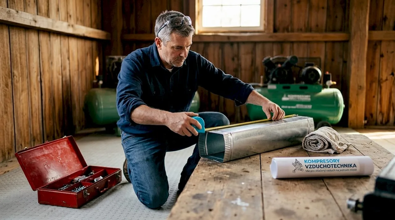
- Measure all duct lengths according to the design documentation. Add 10 mm for every joint inserted into a fitting.
- Cut the ducting with aviation snips or an angle grinder. The cut must be straight and square.
- Remove all sharp edges with a file or abrasive paper. Sharp spots damage the seal and represent a safety risk.
- Mark every part with a marker according to the installation drawing. When installing at height this saves time and nerves.
Joining and fixing the ducting
- Apply sealing tape or sealant to the outer circumference of the spigot. The seal must cover the whole circumference without gaps.
- Push the duct fully into the fitting. If the spigot resists, check that the cut is straight.
- Secure the joint with rivets or screws at a spacing of no more than 150 mm. For larger diameters (over 315 mm) add circumferential clamps.
- Tape over the whole joint with aluminium tape across the full width of the overlap. The tape must adhere to a clean, dry surface.
Professional tip: Always press aluminium tape down with a plastic spatula or a stiff card. Pressing it with your fingers alone is not enough and the tape peels off over time, especially with temperature changes.
Fixing to the load-bearing structure
- Fix the ducting with hangers or clamps at a spacing of no more than 1200 mm for round cross-sections up to DN 200. For larger diameters reduce the spacing to 900 mm.
- Every hanger must be anchored into the load-bearing structure, not just into plasterboard or the suspended ceiling.
- Fix horizontal sections so that the fall is no more than 0.5 % towards any condensate drain.
Never hang ducting from other services (electrical or plumbing installations). A vibrating air system can damage the surrounding lines.
Insulation and final sealing
- Apply the insulation to clean, dry ducting. Tape the insulation joints with aluminium or insulating tape without gaps.
- Insulation prevents condensation on cold ducting and reduces system noise.
- Once the whole section is finished, inspect every joint visually. Sealed joints should have no visible gaps and no loose tape edges.
For a detailed procedure for installing ventilation systems, we also recommend studying the practical installation procedure.
| Step | Description | Most common mistake |
|---|---|---|
| Cutting | Straight, square cut without burrs | Angled cut, leaking joint |
| Seals | Tape or sealant around the whole circumference | Incomplete coverage of the circumference |
| Riveting | Spacing max. 150 mm | Too few rivets |
| Aluminium tape | Press down along the whole length | Air bubbles under the tape |
| Hangers | Anchor into the load-bearing structure | Anchoring into plasterboard |
Technical parameters and route design
Efficient step-by-step ventilation installation does not rest on good joints alone. What also matters is how the whole system is designed.
Recommended velocities and sizing
The optimum air velocity in distribution ducting is approximately 4 m/s. At higher velocities both noise and pressure losses increase. At lower velocities, on the other hand, duct cross-sections grow and material costs rise. This trade-off is the key parameter in sizing.
The duct cross-section is calculated from the relationship: airflow (m³/s) divided by velocity (m/s) gives the cross-section in m². Round ducting DN 200 handles approximately 450 m³/h at 4 m/s. This is an indicative value for choosing the diameter in the course of the guide to industrial compressed air distribution.
Minimising bends and route lengths
Short routes and insulated ducting are the key to low noise and good operating efficiency. Every bend represents a resistance roughly equivalent to 1 to 3 metres of straight ducting (depending on the bend radius). When designing the route, minimise the number of changes of direction and prefer bends with a large radius.
- Avoid sharp 90° bends wherever two 45° bends can be used.
- Always resolve crossings with other services in the design documentation, not improvised on site.
- Divide straight sections longer than 6 metres with an expansion joint to absorb thermal expansion.
Professional tip: Document the actual route with photographs before the suspended ceilings are closed up. These photographs are invaluable during later repairs or refurbishments.
Pipe insulation
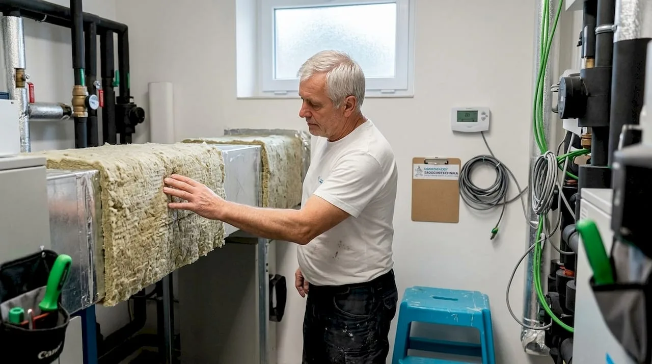
Insulation performs two functions at once: it limits condensation of moisture on cold ducting and reduces noise transmission into the rooms. The recommended insulation thickness for distribution air is 25 mm of mineral wool or an equivalent material. For ducting run in unheated spaces, increase the thickness to 50 mm.
| Type of space | Recommended insulation thickness | Material |
|---|---|---|
| Heated interiors | 25 mm | Mineral wool, PE foam |
| Unheated spaces | 50 mm | Mineral wool |
| Outdoor piping | 80 mm + vapour barrier | Mineral wool with Al cladding |
Inspection and maintenance after installation
A leak test and the first balancing of the system are mandatory steps in every installation. Skipping them means risking problems that only appear once the structures have been closed up.
Leak test
Carry out a pressure test before closing up suspended ceilings or covering any part of the ducting. Leak testing before closing up is the recommended procedure, because repairs in a finished interior are very expensive. Test procedure:
- Close all air terminal devices and control dampers.
- Pressurise the system to 1.25 times the operating pressure.
- Check every joint with a leak detector or a foaming solution.
- Mark and repair any leaks immediately. Repeat the test.
- Record the test result in the installation documentation, with the date and the signature of the responsible person.
Balancing and setting up the system
Primary and secondary balancing of a ventilation system takes place in two phases. First the main parts of the system are balanced by setting the control dampers on the main branches. Then secondary balancing of the individual branches and air terminal devices follows, based on the measured airflows.
- Measure the airflow at every outlet with an anemometer or a measuring hood.
- Compare the measured values with the design values. The deviation should not exceed 10 %.
- Document the setting of the control dampers (position, measured airflow, date).
Professional tip: Carry out balancing at full fan output. Settings made at reduced output do not correspond to real operation and the system will be unbalanced once it runs at full output.
Regular maintenance after installation includes cleaning the filters (usually every 3 to 6 months), visual inspection of the condition of the ducting and hangers, and measuring airflows once a year. Keeping a service log makes later fault diagnosis considerably easier. We also recommend following the tips on optimising air consumption to reduce operating costs.

The most common problems after installation
Noise in the ducting is most often caused by air velocity that is too high, or by unsecured ducting vibrating in its hangers. Condensation on the ducting signals insufficient or damaged insulation. Unbalanced airflows point to incorrectly set control dampers or to an error in sizing. Each of these problems has a clear solution, provided you have good installation documentation.
From practice: what determines installation quality
In my experience, the biggest problem on ductwork installations is not a lack of technical knowledge but insufficient planning and an unclear division of responsibility within the team. I have seen projects where everyone relied on somebody else checking the route. The result was predictable: the ducting crossed the electrical installation and the inspection openings were inaccessible a week after completion.
I have become convinced that clearly defined responsibility for every step of the installation is just as important as the technical quality of the work itself. Every member of the team should know exactly which duct sections they are answerable for, and confirm each completed section with a signature in the installation record.
The second thing that repeatedly determines the outcome is documentation. Photographs of the as-built condition before the suspended ceilings were closed have personally saved me many hours of work when dealing with faults later on. A client who needs to find a particular joint or damper after two years will be very grateful for those photographs.
Finally: do not neglect the leak test just because you are under time pressure. Repairing a single leaking joint behind a suspended ceiling costs more than the entire test. This applies without exception on every project, regardless of size.
— Zdeněk
Equipment for ductwork installation
Quality ductwork installation requires reliable tools. Kompresory-vzduchotechnika offers a complete range for installation professionals and experienced DIY fitters alike.
For connecting and tightening joints and for work with riveters or air tools, the shop offers Professional KIT gun sets designed specifically for ventilation installation. The sets contain tools for various duct diameters and joint types. Supplementary M7 air tools speed up the anchoring of hangers and the fitting of control elements. The technical team at Kompresory-vzduchotechnika is available for advice on tool selection and for service support after installation.
FAQ
What air velocity is recommended for distribution ducting?
The recommended air velocity in distribution ducting is approximately 4 m/s. This value ensures an acceptable noise level and acceptable pressure losses.
When should a duct leak test be carried out?
Always carry out the leak test before closing up suspended ceilings or otherwise enclosing the ducting. Repairs in a finished interior are considerably more expensive than a preventive test.
How often should ventilation system filters be cleaned?
Clean or replace the filters every 3 to 6 months, depending on how polluted the environment is and how intensively the system is used.
What is balancing of a ventilation system?
Balancing is the setting of the control dampers so that the airflow at every outlet matches the design values. It is carried out in two phases: primary balancing of the main run and secondary balancing of the branches.
What airflow is sufficient for residential rooms?
For residential rooms an airflow of 20 to 40 m³/h per person is recommended, with the target CO2 concentration not exceeding 1000 ppm.
Recommended
- How to install air handling equipment correctly: a practical procedure - Kompresory-Vzduchotechnika.cz
- How to repair an air leak on a compressor: a 2026 guide - Kompresory-Vzduchotechnika.cz
- How air valves work: their key role and efficient solutions - Kompresory-Vzduchotechnika.cz
- A guide to industrial air distribution: operating efficiency - Kompresory-Vzduchotechnika.cz