

TL;DR:
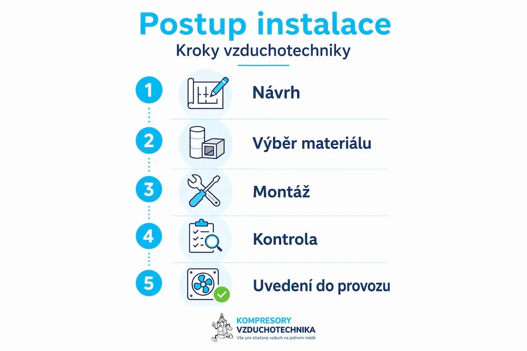
- Correct design, sizing and careful installation are the key to a hygienically safe and efficient ventilation system. What matters is not only mounting the ductwork, but also properly executed penetrations, joints and verified system tightness. Follow these steps and you minimise running costs, noise and the risk of failures.
An economical, hygienically safe and reliable ventilation system is not primarily the result of choosing powerful units. The decisive factors are the design of the ductwork, careful installation and thorough verification of every detail. What matters is not only mounting the ducts themselves, but also the design, sizing and delivery of the required parameters including airflow rates, pressure losses, acoustics, hygiene and fire safety. This article offers a structured procedure from design through physical installation to system start-up, specifically and without unnecessary generalities.
Contents
- Step 1: Design, sizing and preparing the installation
- Step 2: Mechanical installation – supports, joints and penetrations
- Step 3: Checking tightness, insulation and cleanliness
- Step 4: The most common mistakes, complications and how to avoid them
- Step 5: Commissioning the system and verifying the parameters
- What most often fails in practice and why details matter
- Top-quality components for efficient ventilation installation
- Frequently asked questions
Key Takeaways
| Point | Details |
|---|---|
| Quality preparation | A detailed system design affects efficiency, hygiene and savings. |
| Emphasis on correct joints | Tightness and the type of joints determine long-term function and running costs. |
| Correct insulation | Pre-insulated ductwork and careful installation minimise both losses and noise. |
| Thorough checks before start-up | Test mode, airflow measurement and the elimination of leaks are essential before commissioning. |
| Preventing mistakes | Timely inspection, cleanliness and thorough workmanship prevent future problems. |
Step 1: Design, sizing and preparing the installation
Design preparation is the foundation on which every subsequent step depends. A mistake built into the design multiplies during installation and even more during operation. The operating efficiency of the distribution system depends on how accurately the design captures the real requirements of the plant.
What the design must cover
Every ventilation installation design must address these basic areas:
- Airflow rates for each branch and each outlet, expressed in m³/h or l/s
- Pressure losses across the whole route including local resistances (bends, branches, fittings)
- Acoustics – maximum permissible noise levels in the served rooms
- Hygiene requirements – duct materials resistant to biological contamination, accessible for cleaning
- Fire safety – fire dampers, penetrations with the required resistance, EI classification
- Duct routes and their coordination with the other trades (electrical, plumbing, structure)
Sizing the duct cross-section directly affects air velocity. Recommended values range between 3 and 8 m/s in the main branches and up to 3 m/s at the supply outlets. Exceeding these values causes noise and higher pressure losses, which increases running costs.
Choosing duct materials
The choice of material depends on the type of application, the operating environment and hygiene requirements. A detailed comparison is summarised in the following table:
| Duct type | Material | Typical application | Advantages | Disadvantages |
|---|---|---|---|---|
| Round galvanised | Steel | Industry, manufacturing | Strength, durability | Higher weight, insulation required |
| Rectangular galvanised | Steel | Office buildings | Space saving | More demanding installation |
| Plastic (PVC, PP) | Plastic | Areas with chemical exposure | Corrosion resistance | Lower strength, limited temperature resistance |
| Flexible ducting | Aluminium, plastic | Connecting outlets | Easy installation | Higher pressure losses when compressed |
| Pre-insulated | Metal or plastic with insulation | Ventilation with heat recovery | Simpler installation | Higher purchase price |
| Stainless steel | Stainless | Food industry, cleanrooms | Hygiene, corrosion resistance | High price |
Choosing a material is not only a question of price. In areas with high hygiene demands, for example in catering operations or clean production halls, using stainless or hygienically certified ductwork is mandatory, not optional.
Dust and fire protection measures in the design
Penetrations through fire compartments must be resolved at the design stage. Every penetration of a ceiling or wall in a fire-separating structure requires a fire damper or collar with the corresponding EI classification. These elements must be drawn into the design with an exact specification and coordinated with the construction trade. Drilling into fire walls or ceilings afterwards complicates the certification of the building and increases costs.
Dust protection measures include sealing openings and protecting the ductwork against construction dust during installation. Open duct ends must be covered with caps or foil throughout the installation.
Professional tip: Specify all typical penetrations through structures in the design documentation. Subsequent modifications are in practice many times more demanding and more expensive and increase the risk of leaks or insufficient fire resistance. Coordination with the building designer saves both time and money.
A detailed overview of the steps for connecting the distribution system will help verify whether the design covers all the required nodes.
Step 2: Mechanical installation – supports, joints and penetrations
Once the design has been thought through and the materials are ready, the physical work itself and the installation detail follow. The installation principles for ventilation ductwork cover above all supports and brackets, correct jointing, tightness checks, the handling of penetrations and maintaining cleanliness before commissioning.
Mechanical installation procedure
- Setting out the routes according to the design, marking the positions of supports and penetrations in the building
- Fitting supports and brackets before duct installation, spacing according to the diameter and weight of the duct (typically 1.5 to 3 m)
- Preparing the duct sections – cutting, forming, preparing spigots and flanges
- Installing the main branches from the air handling unit towards the outlets
- Joining the sections by the chosen method (see the comparison below)
- Fitting the fire dampers and other fittings exactly at the positions defined by the design
- Executing the penetrations through walls and ceilings with the required tightness and fire resistance
- Connecting flexible hoses to the end outlets or to the equipment
- Closing all open ends before a break or at the end of the working day
- Visual inspection of the whole route before covering or insulating
Comparison of duct jointing methods
The jointing method directly affects tightness, the installation effort and the possibility of later dismantling for maintenance.
| Jointing method | Suitability | Tightness | Dismantling | Effort |
|---|---|---|---|---|
| Press fittings | Round ducting, industry | High | Low | Low |
| Flanged joints | Large diameters, industry | Very high | High | Medium |
| Bolted flanges | Service access points | High | High | Medium |
| Self-locking (click) joints | Pre-insulated systems, installation | Medium to high | Medium | Low |
| Glued joints (PVC) | Plastic ducting | High | Low | Low |
| Silicone seal + clamp | Flexible ducting | Medium | High | Low |
Flanged joints are the standard choice for ducts over 400 mm in diameter or wherever regular inspection or dismantling is required. For smaller diameters in industrial applications, press fittings are efficient and guarantee high tightness without the need for welding.
Penetrations through fire-separating and vapour-tight structures
A penetration through a fire-separating structure must comply with EN 1366-2 or the relevant national regulations. Every penetration must be handled individually according to the type of structure and the required EI classification of the damper or collar. Certified products must be installed exactly according to the manufacturer's instructions, otherwise the certification is void.
Vapour-tight penetrations in external structures require flexible seals or collars that prevent moisture condensation and air infiltration. Neglecting this detail leads to mould inside the structure, which is difficult to remove.
Important: Even the best ventilation equipment will not deliver a safe and functional system without tight, properly executed joints and penetrations. Leaking joints cause loss of performance, noise, the spread of contamination and, in fire penetrations, a safety hazard as well.
The complete step-by-step installation procedure is described in the detailed connection guide, which also covers the specifics of industrial applications.
Step 3: Checking tightness, insulation and cleanliness
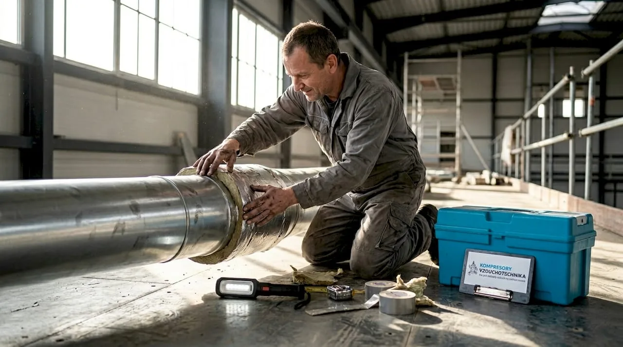
Once the mechanical work is finished, a phase follows in which small details decide long-term function and savings. The right choice of ductwork and insulation affects losses, noise, labour and the risk of leaks, and in heat recovery systems it has a marked impact on the resulting efficiency and hygiene.
Tightness tests of the duct system
A tightness check is a mandatory part of every professional installation. There are three basic approaches:
- Visual inspection – examination of all joints, flanges and penetrations, checking the application of seals and sealant
- Pressure test – pressurising a closed section above the operating pressure (typically 1.5 times) and monitoring the pressure drop over a defined period
- Vacuum test – applying negative pressure to the system and measuring the pressure rise, suitable for ducts with negative-pressure sections
- Leak detection using smoke or a detection fluid (to identify the exact location of a leak)
Standard EN 12237 defines duct tightness classes (A to D), with class C or D normally required for certified energy-efficient systems. Test results are recorded in the installation report.
Typical insulation mistakes
Duct insulation applied on site afterwards brings a risk of leaks and is time-consuming. The most common mistakes are:
- Interrupted insulation at supports or penetrations, where condensation occurs
- Insufficient insulation thickness for the given temperature conditions, causing heat losses
- Unsuitable insulation material in environments with high humidity or chemical exposure
- Poorly taped joints between insulation sections, which open up over time
- Missing vapour barrier in cold areas, leading to condensation inside the insulation
Each of these mistakes reduces the energy efficiency of the system. In heat recovery systems, poor insulation can reduce recovery efficiency by tens of per cent and increase running costs.
Cleanliness of the system before start-up
The cleanliness of the duct system is a condition of hygienic safety. Before closing the system and starting it up, it is necessary to carry out:
- Inspection of the duct interior with a torch or camera on longer routes
- Vacuuming dust and dirt from the whole system with an industrial vacuum cleaner
- A check for installation residues – screws, seals, sealant remnants
- Verification of the cleanliness of the filter sections and replacement of the filters with new ones before start-up
Professional tip: Always favour pre-insulated ductwork to reduce labour and the risk of leaks, especially on complex routes with many branches or in places that are hard to reach for subsequent insulation. The higher purchase cost pays for itself through lower labour and reliable joints. The technical parameters of push-in tubing and insulation allow an exact comparison of the available options.
Step 4: The most common mistakes, complications and how to avoid them
Once the installation process has been mastered, the risk of mistakes still has to be taken into account. Only by knowing them and understanding their causes can problems be prevented systematically. Typical risks of poorly executed installations include air leaks, unsuitable air velocities, complicated routes, missing inspections and faulty penetrations through structures.
The most common operating problems and their symptoms
- Leaking joints – audible as a hissing or whistling sound at the point of the leak, with reduced output at the outlets
- Incorrect sizing – too small a cross-section causes high noise and pressure losses, too large a cross-section causes low velocity and the settling of dirt
- Overly complex or unsuitable routes – an excessive number of bends and branches increases pressure losses and noise
- Faulty penetrations – leaking penetrations or those failing fire requirements endanger safety and cause delays at final approval
- Missing regular inspections – neglected maintenance leads to a gradual drop in performance and rising energy consumption
- Vibration and noise transmitted through the structure – the result of missing anti-vibration pads or unsuitable supports
- Condensation inside the ductwork – caused by insufficient insulation or a badly chosen route through a cold area
Warning: Many ventilation failures in operation are not caused by the equipment itself but by installation details. Do not overlook even "small" deviations from the design. A compromise accepted during installation can turn into a permanent operating problem.
Preventive measures
To eliminate the risks described above, the following measures apply:
- Thorough review of the design before installation begins, verifying coordination with the other trades
- Use of certified components matching the design specification
- Step-by-step installation with ongoing checks instead of postponing the checks to the end
- Documentation of deviations from the design during installation and their approval by the designer
- Tightness checks after each section is completed, not only of the whole system at once
- Testing of the fire dampers including a simulated trip before covering
Maximum air efficiency in industrial applications depends directly on how precisely the design parameters are met. The operating efficiency of the whole system is then the result of coordinating each of these steps. More technical detail is offered by the section on the operating efficiency of industrial air distribution.
Step 5: Commissioning the system and verifying the parameters
Having put the possible risks in perspective, we can highlight the correct start-up steps that provide long-term certainty. Testing a ventilation system after installation requires a test run and verification of tightness and airflow before the system is handed over to the operator.
Commissioning procedure
- Pre-start check – visual inspection of the whole route, closing all service openings, checking the dampers in the open position
- Starting the air handling unit in test mode at minimum output, gradually increasing the speed or output
- Checking vibration and noise during run-up, stopping immediately if unusual sounds are detected
- Measuring the airflow at every outlet with an anemometer or flow meter, comparing it with the design values
- Measuring static pressure at key points along the route to verify the pressure losses
- Verifying the function of the control elements including dampers, flow regulators and automation
- Checking the tightness of the whole system under operating conditions, searching for any leaks
- Documenting the measured values in the commissioning report
- Handover of the system to the operator including documentation, operating instructions and a maintenance plan
- Setting the date of the first regular inspection and recording it in the operating log
Airflow measurement must prove that the actual values correspond to the design values with a maximum deviation of typically ±10 %. Deviations outside this range require adjustment of the balancing dampers or a review of the route.
Regular maintenance includes cleaning the filters (depending on the operating load usually every 3 to 6 months), checking moving parts, a tightness inspection and verification of fire damper function at least once a year.
Technical parameters and specifications are available in the air treatment units section, where you can find components matching specific operating conditions.
What most often fails in practice and why details matter
Practice shows a recurring pattern. Investment in air handling units is high, but the problem is not the performance of the equipment. Problems appear repeatedly in the same areas: leaking joints, shortened routes with an excessive number of bends, missing insulation at penetrations or a skipped tightness check. The cause is almost always a combination of pressure to install quickly and the underestimation of seemingly minor details.
Experience from ventilation installations in industrial plants shows that up to 70 % of warranty claims are unrelated to the equipment and relate instead to how the ductwork was installed. A leaking joint that loses 5 % of the airflow seems harmless. But across dozens of joints on a long route the result is a 20 to 30 % drop in output at the end outlets and a corresponding rise in the running cost of driving the fans.
Time pressure during installation leads to checks of the penetrations being postponed until "after the walls are finished". But once the building work is complete, correcting the penetrations is far more demanding financially and logistically. Saving on insulation has the same effect. The cost difference between pre-insulated ductwork and insulation applied on site afterwards can be relatively small, but the labour involved and the risk of poor insulation are considerably higher.
Another recurring failure is the absence of documentation of deviations from the design. During installation, routes are adjusted for practical reasons without those changes being recorded in the documentation. The result is a situation where, in the event of a fault or a refurbishment, the operator has no accurate map of the system and has to search for the routes with probes or destructively.
The efficiency of a ventilation system in practice is the direct result of respecting every step described above. It is not a question of philosophy or perfection. It is a question of being systematic and following proven procedures that eliminate unnecessary running costs, noise complaints and hygiene failures.
Top-quality components for efficient ventilation installation
The quality of the components directly affects the result of the installation. Correctly sized, certified ductwork and connecting components shorten installation time and reduce the risk of claims.
The Kompresory-vzduchotechnika.cz portal offers components for every step of the described procedure. Tubing for distribution systems covers the common diameters from 15 to 28 mm for both industrial and building applications. The complete compressed air distribution section offers piping components and connecting elements for professional installations. For air quality treatment, certified compressed air treatment units meeting the parameters for industrial operating conditions are available. All products come with technical specifications and expert advice.
Frequently asked questions
Which types of ductwork should be chosen for industrial ventilation?
For industrial applications, pre-insulated ductwork specified for the given operating conditions is ideal, because insulation applied afterwards brings a risk of leaks and is time-consuming. The choice depends on temperature, humidity, chemical exposure and the hygiene requirements of the specific plant.
Do all joints have to be airtight?
Yes, the tightness of all joints is essential for correct operation and energy savings. An emphasis on the tightness and accessibility of joints is defined as a basic installation principle for ventilation ductwork. Leaking joints cause loss of performance, noise and, in the case of fire penetrations, safety risks as well.
What are the main mistakes when installing ventilation?
The most common mistakes are air leaks at the joints, incorrect sizing of cross-sections, an excessive number of bends increasing pressure losses and the absence of regular checks. Air leaks, unsuitable velocities, complicated routes and missing inspections are among the most frequently documented operating problems in practice.
How can the correct function of the ductwork be verified before start-up?
Before commissioning it is necessary to carry out a test run with gradually increasing output, measure the airflow at all outlets and check the tightness of the whole system. A test mode and verification of tightness and airflow are a standard part of every professional handover of a ventilation system.
Recommended
- Connecting air distribution systems step by step: 2026 guide - Kompresory-Vzduchotechnika.cz
- Pneumatic system assembly: step by step for professionals - Kompresory-Vzduchotechnika.cz
- Check valve in compressors: technical function and application - Kompresory-Vzduchotechnika.cz
- How to store air hoses correctly: a guide for tradespeople - Kompresory-Vzduchotechnika.cz