


Sizing of a compressed air distribution system is governed by one main rule: the pressure drop between the compressor and the most distant point of use should be as low as possible and kept at a low level. The second rule concerns flow velocity; the main distribution lines are designed so that the velocity stays within a reasonable limit, which protects the system from carrying water and impurities.
The procedure is always the same. You determine the actual air consumption (FAD) of all connected equipment, measure the total pipe length including the equivalent length of fittings and valves, select an approximate diameter from a table or nomogram, and verify the result with a more precise calculation using the Darcy-Weisbach equation.
Key figures for quick orientation:
- The pressure drop should be as low as possible and kept at a low level between the compressor room and the most distant point of consumption
- The recommended velocity in main lines is within a reasonable range, typically around several metres per second
- The velocity in end branches and connections should be lower, adapted to the given section
- The upper velocity limit is set to prevent condensate and impurities from being carried through the piping
Key findings
Correct sizing of a compressed air distribution system consists of maintaining a pressure drop of up to 0.1 bar and a flow velocity of 6 to 7 m/s in the main line, confirmed by calculation and measurement after installation.
| Point | Details |
|---|---|
| Pressure drop limit | Keep the pressure drop between the compressor and the farthest outlet below 0.1 bar. |
| Design velocity | Main lines 6–7 m/s, branch connections 2–4 m/s, absolute maximum 9 m/s. |
| Equivalent lengths | Add the length for each elbow, valve, and T-piece to the actual pipe length. |
| Table and calculation | Tables give a quick estimate, the Darcy-Weisbach equation confirms accuracy for complex networks. |
| Implementation with a specialist | Kompresory-vzduchotechnika provides design, installation, measurement, and service of the distribution system all in one place. |
Contents
- Practical procedure for sizing the air distribution system step by step
- When a table is enough and when an exact calculation is necessary
- What effect does air velocity have on pressure losses
- Selecting pipe and fitting materials for compressed air distribution
- How to verify distribution sizing by measurement after installation
- What makes good sizing truly good
- How Kompresory-vzduchotechnika can help you implement the design
- Frequently asked questions
Practical procedure for sizing an air distribution system step by step
Sizing an air distribution system is not a guess by eye. It is a sequence of five steps that build on one another, and skipping any step usually shows up as low pressure at the end of the line or, conversely, as unnecessarily expensive oversized piping.
- Compile a list of consumption points. For each pneumatic device, determine the actual consumption in l/s or m³/h, not the nominal output from the catalog. In larger facilities, simultaneity of consumption must be taken into account, as not all tools run at the same time.
- Divide the network into sections. The main distribution line, risers, and service connections have different requirements for velocity and permissible pressure drop, so do not size them uniformly.
- Calculate the total and equivalent length. Add the equivalent length for each elbow, T-piece, valve, and reducer to the length of straight pipe. In shorter, densely fitted sections, fittings often account for a larger part of the pressure loss than the straight run itself.
- Choose a rough diameter. Sizing tables, with flow on one axis and pipe run length on the other (typically columns for 25, 50, and 100 meters), give a quick initial estimate of the diameter without having to calculate anything by hand.
- Refine with calculation and verify the velocity. The Darcy‑Weisbach equation with the Reynolds number and pipe wall roughness gives the exact pressure loss. Check that the resulting flow velocity remains within the recommended range for the given section.
You can also verify the specific implementation of the main distribution system using the example of 50 mm air piping systems for industrial operations, where you can see how the sizing translates into the actual performance of the network. The entire installation sequence from design to installation is then described in the guide how to set up a compressed air distribution system step by step.
Professional tip: In step 3, keep a table of equivalent lengths for each fitting separately. For short service connections with several elbows and a ball valve, this sum can surprisingly increase the resulting pressure drop even where a straight run would show no problem.
When a table is enough and when an exact calculation is necessary
The choice of method depends on the size of the project and how much margin for error you have in the budget. For smaller workshops, service operations, or a simple addition to an existing line, a table-based or nomogram-based approach is usually fully sufficient. Sizing tables, such as those published by Czech sources like EQOfluids, work with the relationship between flow rate, line length, and recommended diameter, and give a usable result within a few minutes.
For larger industrial networks, where the consumption of dozens of machines is summed up and the line runs through multiple floors or halls, the table-based estimate becomes inaccurate. This is where an exact calculation comes in:
- The Darcy‑Weisbach equation calculates the pressure loss from the flow velocity, pipe length, diameter, and friction coefficient.
- The Reynolds number determines whether the flow is laminar or turbulent, which affects the choice of friction coefficient.
- The roughness of the inner pipe surface is entered into the formula according to the material, steel piping has a different roughness than plastic or aluminum.
A table gives you a quick estimate. A calculation gives you the certainty that the estimate holds for your specific material, line shape, and operating conditions. For critical operations, this step cannot be avoided.
To verify the result, it is worth using an online pipe hydraulic resistance calculator that works with the Darcy‑Weisbach equation and a list of fittings. Such a tool will confirm within moments whether the table-based diameter estimate matches the exact calculation, or whether the dimension needs to be increased. Combining both methods, a table for the initial estimate and a calculation for confirmation, is in practice the fastest way to a reliable design.
What effect does air velocity have on pressure losses
In practice, pressure drop is not distributed evenly along the entire length of the network. A reasonable distribution looks like this:
- Main line from the compressor room: the lowest share of the drop, with some design procedures recommending keeping it below 0.03 bar
- Distribution branches to individual halls or sections: medium share of the total drop
- Service connections to individual machines: the remaining reserve up to the overall limit of 0.1 bar
A high flow velocity above 9 m/s brings three specific problems. It increases the noise level of the distribution system, which is particularly noticeable with metal pipes routed along the walls of halls. It allows condensate and mechanical impurities to be carried further into the system, which puts a load on filters and end devices. And finally, it increases the pressure loss with the square of the velocity, so even a small oversizing of the pipe flow results in a disproportionately large pressure drop and thus also higher energy consumption of the compressor.
When designing the main distribution line, it pays off in the long term to choose a diameter one size larger than current consumption indicates. Expanding production with additional machines is common, and a subsequent pipe replacement will always cost more than the initial reserve. The relationship between pipe diameter and operational efficiency is also well described by the guide to industrial air distribution focused on operational efficiency.
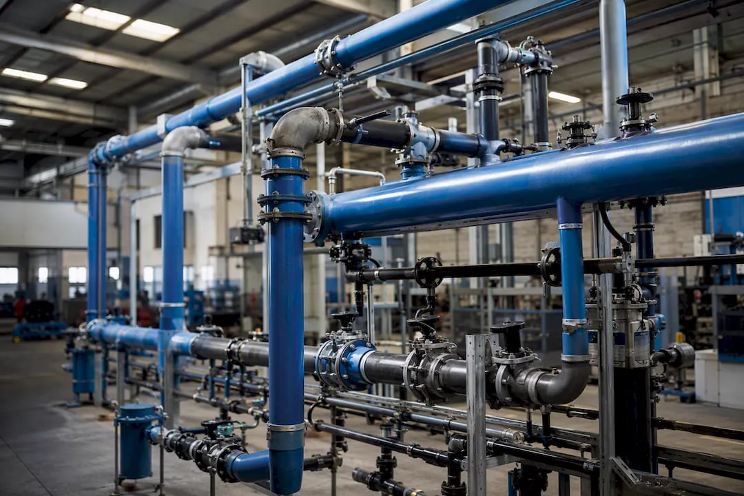
Selecting pipe material and fittings for the compressed air distribution system
The pipe material affects the roughness of the inner surface, and thus directly enters into the calculation of pressure loss. At the same time, it determines the resistance to corrosion and the overall service life of the distribution system.
- Steel pipe is mechanically durable, but without a surface treatment it is subject to corrosion, which shows up as increased surface roughness and, over time, also as higher pressure losses.
- Stainless steel pipe has the best corrosion resistance, is suitable for operations with high humidity or aggressive environments, but the price is higher.
- Aluminum pipe combines low weight, a smooth inner surface, and good corrosion resistance; installation is faster thanks to the lower weight of the components.
- Plastic systems have very low surface roughness and are resistant to corrosion, but their use is limited by the maximum operating pressure and temperature according to the manufacturer's specifications.
For push-in and quick-assembly systems, it is worth looking at the range of push-in pipe systems, which simplifies the selection of materials and fittings. Keep the number of elbows, tees and valves on the line to a minimum, as each fitting adds an equivalent length to the pressure drop calculation, and for short sections this can mean the difference between a compliant and a non-compliant design.
How to verify the pipework sizing by measurement after installation
A design on paper is one thing, actual operation is another. Verification is carried out in three steps:
- Measure the pressure at key points. Using a pressure gauge or differential pressure sensor, compare the pressure at the compressor room outlet and at the farthest point of use under full operating load.
- Compare the measured difference with the design limit of 0.1 bar. If the deviation is within a tolerance of a few hundredths of a bar, the design is correct. A more significant deviation indicates an undersized section, a clogged fitting, or a leak.
- Record the results in the handover protocol. For larger installations, it is worthwhile to note the measured values of pressure, temperature, and possibly flow velocity in individual sections, so that the data can be revisited in case of future network expansion.
Professional tip: Always measure during actual consumption, not in an idle state without load. A pipework system that is compliant without load can easily exceed the 0.1 bar limit during full operation of several machines at once.
Author Zdeněk's experience: common mistakes and installation tips
The most common recurring mistakes in practice are: underestimating the equivalent length of fittings, sizing based on the nominal output of tools instead of actual consumption, and using a single diameter for the entire network regardless of the different requirements of the main line and branch connections.
Before ordering pipework, check this checklist:
- Have you summed up the actual consumption of all outlets, taking simultaneity into account?
- Did you account for the equivalent length of each fitting on the line?
- Does the selected diameter correspond to the recommended velocity of 6–7 m/s in the main line?
- Do you have a reserve in diameter for future expansion of operation?
During installation, minimize the number of unnecessary elbows, mount the piping so that no stress arises in the joints, and after commissioning check all threaded and pressed joints with a leak detector.
What makes good sizing truly good
The most common mistake I see in distribution system designs is not a wrong formula. It is underestimating the equivalent length of fittings and overestimating the accuracy of tables for complex networks with many branches. A table is an excellent tool for an initial estimate, but on a route with ten elbows and five valves over twenty meters, it will give a distorted result unless the fittings are counted honestly.

The second thing that conventional advice underestimates: a reserve in diameter almost always pays off. Investing in pipework one size larger is a fraction of the cost of later replacing the entire line when operations expand with additional machines. If you have to choose between "exactly according to the calculation" and "with a small reserve for expansion", choose the reserve for the main line.
The reader's priority should be clear: first correctly determine the actual consumption (not catalog values), then account for equivalent lengths, and only at the end decide whether a table is sufficient or an exact calculation according to the Darcy-Weisbach equation is necessary. The reversed order of priorities is the reason why undersized distribution systems appear so often.
— Zdeněk
How Kompresory-vzduchotechnika will help you implement the design
A design on paper is half the work; the other half is correct implementation and air quality at the end of the pipeline. Kompresory-vzduchotechnika offers turnkey distribution system design, on-site pressure drop measurement, installation, and subsequent service, so you don't have to combine several suppliers for one project.
The calculated pipe diameter is usually also linked to the choice of air treatment at the end of the route. In our offer you will find compressed air treatment units up to 18 bar as well as a filtration program according to the ISO 8573 standard, which addresses air quality according to the actual requirements of end equipment. If you are still choosing a suitable compressor for the designed distribution system, also browse the category of piston and screw compressors.
For a non-binding inquiry, prepare the basic data from the checklist: total air consumption (FAD) in l/s or m³/h, lengths of individual pipe sections, number and type of outlet points, and an approximate plan for future expansion of operations. With this data, the technicians at Kompresory-vzduchotechnika will design the distribution system dimension and suitable air treatment tailored to your operation.
Frequently Asked Questions
What is the maximum permissible pressure drop in the distribution system?
The target value is 0.1 bar between the compressor and the most distant point of use; for the main line, it is recommended to keep significantly below this limit.
What is the recommended flow velocity in compressed air piping?
Main distribution lines are designed for 6 to 7 m/s, end connections tend to be slower, around 2 to 4 m/s, and the limit of 9 m/s must not be exceeded due to the risk of condensate entrainment.
When should a table be used and when is an exact pipe sizing calculation needed?
A table or nomogram is sufficient for smaller and simpler distribution systems; for extensive industrial networks with many branches, the result must be verified using the Darcy-Weisbach equation.
How does the equivalent length of fittings affect the calculation?
Every elbow, valve, or T-piece is included in the calculation as additional length of straight pipe; in short, densely fitted sections, this often accounts for a greater part of the pressure loss than the route itself.
Can Kompresory-vzduchotechnika help with distribution system sizing?
Kompresory-vzduchotechnika offers turnkey distribution system design, pressure loss measurement, and installation, so both the technical calculation and the implementation can be secured from a single supplier.
Recommended
- How to set up compressed air distribution step by step - Kompresory-Vzduchotechnika.cz
- Procedure for assembling air distribution: an installation guide - Kompresory-Vzduchotechnika.cz
- Guide to industrial air distribution: operating efficiency - Kompresory-Vzduchotechnika.cz
- Benefits of centralized air distribution in industry - Kompresory-Vzduchotechnika.cz