

Summary:
- Pneumatic logic uses compressed air to control functions without electrical energy. It is used in industrial automation, where it emphasizes reliability and simplicity. Proper design and documentation according to standards increase its efficiency and the service life of systems.
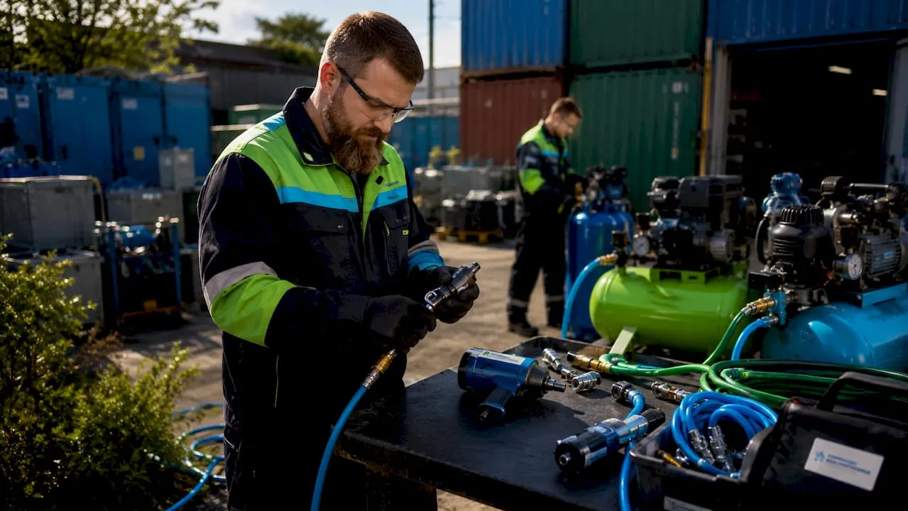
Pneumatic logic is a control system that uses compressed air to implement logical functions such as AND, OR, and NOT, without the need for electrical energy. This approach is used in industrial automation, on production lines, and in construction, where system reliability and simplicity take precedence over complex electronics. Standards such as ISO 1219-2 and ANSI/JIC define standardized methods for designing and documenting these systems. Pneumatic logic combines thermodynamics, fluid mechanics, and control theory into a single functional unit capable of controlling cylinder movements, motion sequences, and safety interlock functions.
What is pneumatic logic and how does it work?
Pneumatic logic is defined as the use of compressed air to transmit and process control signals in technical systems. Unlike electrical logic, which operates with voltage and current, pneumatic logic operates with pressure impulses passing through valves and piping. The result is a system resistant to electromagnetic interference, explosive environments, and high humidity.
Pneumatic theory states that pneumatics is not just air in pipes, but controlled energy transfer using thermodynamics, fluid mechanics, and control theory. This combination of disciplines makes it possible to design systems that respond precisely and repeatably even under demanding operating conditions.
Basic components of a pneumatic logic system
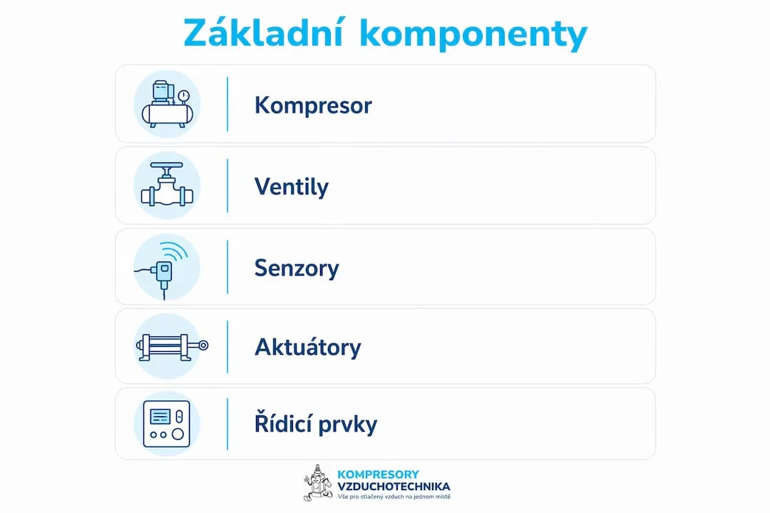
Every pneumatic logic system consists of several key elements:
- Pneumatic logic valves implement the AND, OR, and NOT logical functions using pressure signals. Input pressure opens or closes the air flow at the output.
- Pressure regulators maintain the operating pressure within the required range. Integrated logic regulators typically operate in the range of 2–8 bar and at temperatures from -15 °C to +60 °C.
- Pneumatic timers provide a time delay between individual steps of a sequence. Their accuracy and repeatability must be verified before being put into operation.
- Pneumatic counters track the number of cycles or pulses and enable conditional process control.
- Interlocking elements prevent the simultaneous activation of conflicting signals and protect valves and actuators from damage.
Professional tip: When designing a system, always verify that the operating pressure matches the specifications of each logic element individually. A pressure deviation outside the permitted range causes unreliable valve switching.
The AND logic function in pneumatics requires a pressure signal to be present at both inputs simultaneously in order to open the output. The OR function allows air through if at least one of the inputs is active. The NOT function inverts the input signal. These three basic functions form the building blocks of more complex control sequences.
What standards apply to the design of pneumatic systems?
The design and documentation of pneumatic logic systems is governed by several internationally recognized standards. Compliance with them is not just a formal requirement. Standards directly affect reliability, the clarity of documentation, and the speed of fault diagnosis.
Sequence diagrams according to ISO 1219-2 visualize the time relationships between individual steps of a sequence and enable precise design as well as efficient maintenance. Underestimating documentation significantly complicates repairs and extends production downtime.
| Standard | Area of application |
|---|---|
| ISO 1219-2 | Graphic symbols and sequence diagrams for pneumatic circuits |
| ANSI/JIC | American standard for hydraulic and pneumatic system diagrams |
| IEC 60848 | GRAFCET language for describing sequential control systems |
| VDI 3260 | German standard for pneumatic circuits and their documentation |
Each of these standards approaches documentation from a different angle. ISO 1219-2 focuses on graphic symbols and sequential diagrams. IEC 60848 defines the GRAFCET language, which describes sequences of steps and transitions in the form of a state diagram. VDI 3260 is widespread mainly in German-speaking countries and in Central European industry.
Professional tip: When designing a new system, start with a sequential diagram according to ISO 1219-2 before selecting components. The diagram will reveal potential signal conflicts before they generate the cost of physical prototypes.
Accurate recording of valve time constants in the documentation is essential for system stability. The time constant of a valve determines how quickly the valve responds to a control signal. If this value is missing from the documentation, the technician has no basis for comparison in the event of a fault, and diagnostics take significantly longer.
Where is pneumatic logic used in industry and construction?
Pneumatic logic finds application wherever it is necessary to control movements, sequences, or conditional functions without dependence on electrical infrastructure. Industry and construction offer dozens of specific applications.
The most common uses include:
- Control of pneumatic cylinders in assembly lines, where the sequence of movements must take place in an exact order. Pneumatic logic ensures that cylinder B moves only after cylinder A has completed its movement.
- Handling systems for moving parts between workstations. Pneumatic logic circuits coordinate grippers, rotary tables, and conveyor belts.
- Production lines in the food and pharmaceutical industry, where electrical equipment poses a risk of contamination or explosion. Purely pneumatic control eliminates this risk.
- Construction machinery and lifting equipment, where pneumatic logic controls safety sequences and interlock functions.
- Test stations for verifying the tightness or strength of products using pressure tests.
Automation in pneumatics in production processes shows that a properly designed pneumatic logic system reduces dependence on operators and increases production repeatability. Modern intelligent pneumatic control combined with IoT and edge computing can reduce energy costs by 25–35%. This saving results from precise control of air consumption and the elimination of unnecessary leaks or overpressurization.
Pneumatic logic is also used in sorting and packaging systems. Logic circuits here decide on product routing based on pressure signals from sensors. The result is fast and reliable sorting without complex electronics.
How does proper design increase the reliability of a pneumatic system?
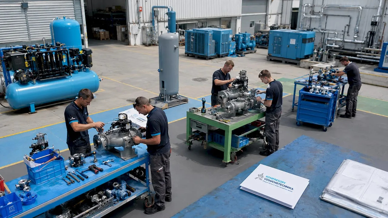
The reliability of a pneumatic logic system depends directly on the quality of its design. Design errors manifest as random failures, incorrect sequences, or component damage.
The recommended design procedure includes the following steps:
- Creating a sequence diagram before selecting any components. The diagram reveals signal conflicts and allows the sequence logic to be verified on paper.
- Selecting components according to operating conditions. Pressure, temperature, cycle frequency, and medium type must match the specifications of each component. Proper component selection can eliminate up to 90% of control failures. This figure shows that most failures do not result from wear but from faulty design.
- Validation of timers and interlock elements. Pneumatic timers must demonstrate accuracy and repeatability at different temperatures and pressures. Testing takes place before commissioning, not after the first failure.
- Implementation of interlock protection. Interlock protection prevents the simultaneous transmission of conflicting signals. Without it, there is a risk of mechanical damage to cylinders or valves when conflicting commands are activated at the same time.
- Preventive maintenance setup. Regular filter inspection, automatic lubricators and seals extends system service life. Monitoring operating pressure and flow detects leaks before they cause a failure.
Safety features form an integral part of every reliable system. Pneumatic safety in industry includes not only anti-blocking protection but also safety valves, position sensors and emergency relief circuits. These elements protect both the equipment and the operator.
Modern pneumatic automation increasingly integrates IoT communication protocols and edge computing for predictive maintenance. Sensors monitor pressure, flow and temperature in real time. The system alerts to a deviation from normal condition before a failure occurs.
Key findings
Pneumatic logic is a reliable foundation of industrial automation, whose performance depends on proper design, standardized documentation and regular component validation.
| Point | Details |
|---|---|
| Definition of pneumatic logic | A control system using compressed air to implement AND, OR and NOT logic functions. |
| Operating parameters | Logic controllers operate in the range of 2–8 bar and temperatures from -15 °C to +60 °C. |
| Impact of design on reliability | Correct component selection eliminates up to 90% of pneumatic control system failures. |
| Key standards | ISO 1219-2, ANSI/JIC, IEC 60848 and VDI 3260 define standards for design and documentation. |
| Energy savings | Intelligent pneumatic control reduces energy costs by 25–35% compared to conventional systems. |
Pneumatic logic in practice: what technicians overlook
I have worked with pneumatic systems for many years, and I repeatedly encounter the same problem. Technicians pay great attention to selecting valves and cylinders, but devote minimal time to documentation and sequence diagrams. The result becomes apparent at the first major failure. Nobody knows what time constants were set during commissioning, and diagnostics take days instead of hours.
The second thing that surprises me is the underestimation of anti-lockup protection. I have seen systems where this function was completely missing. When conflicting signals were activated simultaneously, both the valves and the mechanical parts of the cylinder were damaged. The repair cost many times more than a correct design from the start.
Trends in automation are clearly moving toward integrating pneumatics with IoT sensors and predictive maintenance. This combination makes sense, but the basic prerequisite is having a correctly designed and documented pneumatic circuit. Without a solid foundation, no smart add-on will help.
I recommend one rule to technicians and designers: a sequence diagram according to ISO 1219-2 is a mandatory output of every project, not an optional addition. Systems with quality documentation are repaired faster, more cheaply, and with less risk of error during repair.
— Zdeněk
Pneumatic components and expert support in one place
Kompresory-vzduchotechnika offers a range of pneumatic components for industrial and construction applications, from pressure regulators and logic valves to accessories for compressed air distribution.
The technical support team at Kompresory-vzduchotechnika helps with selecting the right components for a specific application. Whether designing a new system or replacing existing components, expert advice shortens the time from selection to a functional solution. The entire range of pneumatics and hydraulics is available online with the option of consultation. For compressed air distribution, push-in system pipes are also available in diameters of 15–28 mm.
Frequently Asked Questions
What is pneumatic logic and what is it used for?
Pneumatic logic is a control system that uses compressed air to implement AND, OR, and NOT logic functions without electrical energy. It is used to automate movement sequences, control cylinders, and provide safety interlock functions in industry and construction.
What pressure do pneumatic logic elements require?
Integrated pneumatic logic regulators operate within a range of 2–8 bar and temperatures from -15 °C to +60 °C. Exact values depend on the specific type of component and manufacturer.
What is the difference between pneumatic and electrical logic?
Pneumatic logic works with pressure signals and does not require electrical energy, making it suitable for explosive or damp environments. Electrical logic offers faster switching speeds and easier integration with digital control systems.
Why is documentation of pneumatic systems so important?
Sequence diagrams according to ISO 1219-2 visualize the time relationships and logic of sequences. Without proper documentation, fault diagnosis takes significantly longer, and the risk of error during repair increases.
How does pneumatic logic save energy?
Smart control of pneumatic systems combined with IoT sensors reduces energy costs by 25–35% through precise control of air consumption and the elimination of leaks. Pneumatic logic itself saves energy by not requiring power for control elements.
Recommended
- What is pneumatic automation: a guide for industry - Kompresory-Vzduchotechnika.cz
- How pneumatics works: a complete guide for industry 2026
- What is pneumatic lubrication: a guide for technicians - Kompresory-Vzduchotechnika.cz
- The Role of Automation in Pneumatics in Manufacturing Processes - Kompresory-Vzduchotechnika.cz