
In brief:
- Proper pneumatic safety combines fast emergency valves, SIL circuits and physical interlocking, which significantly reduces the risk of serious injuries. Key elements are emergency valves with a response time of up to 50 ms, monitoring of their status and robust interlocking mechanisms, which must not be confused with one another. Also important is the analysis of common cause failures and compliance with standards, in order to ensure real protection of workers.
Pneumatic safety is defined as a set of technical measures and systems designed to prevent accidents and protect workers during the operation of pneumatic equipment in industry. It includes three key components: emergency shut-off valves with a response time of 15–50 ms, safety circuits with a SIL level and dual-pressure interlocking preventing accidental release of pressure. Properly implemented pneumatic safety systems reduce the risk of serious injuries by 96–99%. For technicians and managers in manufacturing, this means a clear framework: without these elements, it is impossible to meet legislative requirements or to ensure real protection of operators.
What does pneumatic safety mean and how do its key components work?
Pneumatic safety is built on three functional layers: rapid circuit shut-off, physical pressure interlocking and controlled system status monitoring. Each layer performs a different function and they complement one another.
Emergency shut-off valves
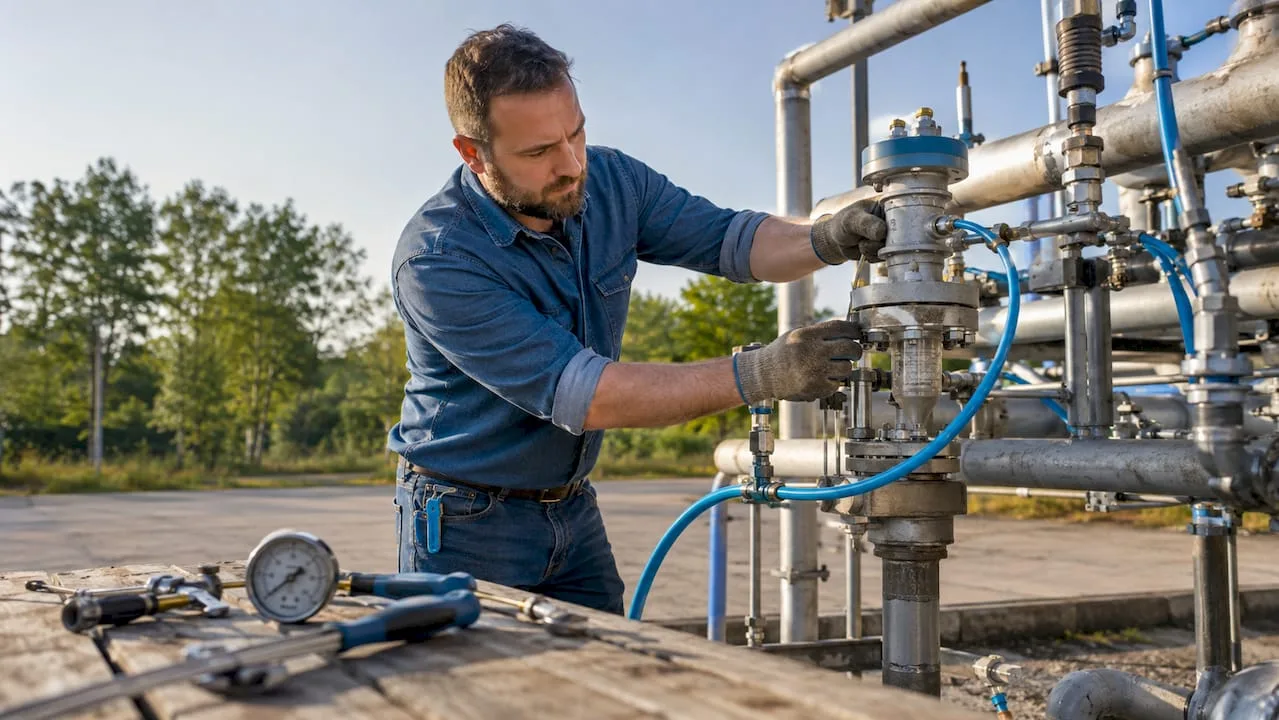
Emergency shut-off valves must close the pneumatic circuit within 15–50 ms. This speed is crucial: human reaction time is approximately 200 ms, so the valve must act before the operator even registers the danger. Standard designs use dual solenoids with dynamic coil position monitoring. This arrangement ensures automatic diagnostics and fault tolerance within safety circuits with a SIL level.
Valve status monitoring is not an optional add-on. Without continuous feedback on the spool position, it cannot be confirmed that the valve has actually closed the circuit after an emergency stop activation. A correct safety circuit design therefore includes redundant position sensors and automatic test cycles.
Pneumatic interlocking versus a safety switch
These two elements perform fundamentally different functions, yet in practice technicians often confuse them. Pneumatic interlocking forms a physical barrier against accidental release of pressure. It mechanically isolates the energy source and prevents the system from restarting without a deliberate intervention by the operator.
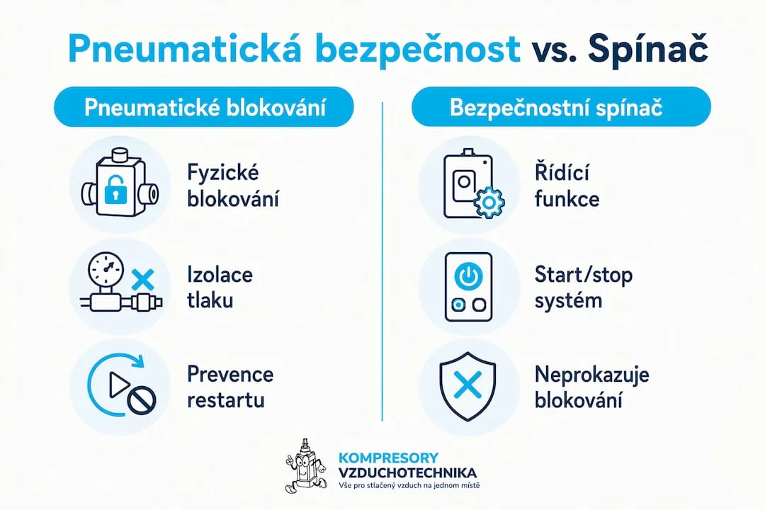
A safety switch, on the other hand, controls system operation in start/stop mode. It does not physically prevent accidental release of pressure, so it cannot be used as a substitute for interlocking during servicing work or when entering a hazardous zone. Both elements are necessary and complement one another.
The role of safety circuits with a SIL level
Safety circuits with a SIL (Safety Integrity Level) rating determine how reliably a system will perform its safety function when a stop is required. A higher SIL level means a lower probability of failure on demand (PFDavg). Redundancy in the circuit, meaning the duplication of valves or sensors, directly increases the achieved SIL level. Without a correctly designed circuit, there is no guarantee that the safety function will operate exactly when it is most needed.
Professional tip: When designing a safety circuit, always verify whether the valve manufacturer provides certified PFDavg and B10d values. Without this data, SIL level validation cannot be performed.
How does pneumatic safety reduce risks in manufacturing operations?
A comprehensive approach to pneumatic system safety reduces the risk of serious injury by 96–99%. This figure applies to systems combining fast-acting valves, SIL circuits, and properly sized interlocks. A single emergency valve without redundancy and monitoring will not achieve such a result.
Valve response speed directly affects the extent of injury. A valve responding within 50 ms shuts off the circuit before the moving part of the machine comes into contact with the operator. A valve with a response time of 200 ms or more does not provide this protection. Correct sizing therefore includes calculating the stopping time of the entire motion system, not just the valve itself.
Safety measures in pneumatics also directly affect operational reliability. A system with automatic diagnostics detects valve degradation before it causes an unplanned production stoppage. A preventive approach thus reduces the costs of unplanned downtime while keeping safety functions operational.
The legislative framework in the Czech Republic and the EU requires machine manufacturers to demonstrate compliance with standards such as EN ISO 13849 or EN 62061. These standards directly reference performance levels (PL) and SIL levels that safety circuits must meet. Failure to comply with these requirements means not only legal liability but also higher insurance premiums and the risk of production shutdown during inspection.
Professional tip: When assessing compliance with EN ISO 13849, be sure to include the entire safety chain: the sensor, the logic, and the actuator. A fault in any one link will reduce the overall performance level of the system.
What hazards do pneumatic systems present and how can they be prevented?
Pneumatic systems involve four main categories of risk: uncontrolled air exhaust, residual pressure after shutdown, energy release, and mechanical failures caused by contamination.
Hazards of uncontrolled exhaust
Exhaust air can cause mechanical injuries, hearing damage, and component failure. Noise from direct exhaust exceeds 100 dB, while cumulative exposure above 85 dB damages hearing with prolonged exposure. The kinetic energy of particles carried by air at a speed of 100 m/s is sufficient to penetrate skin or damage the eye.
Exhaust velocities above 30 m/s in accessible locations are considered hazardous. ISO 4414 therefore recommends flow regulation as a standard measure. Noise mufflers, flow regulators, and special exhaust piping are specific technical solutions that eliminate this risk.
Overview of main hazards and protective measures
| Type of hazard | Cause | Protective measure |
|---|---|---|
| Exhaust noise | Direct exhaust above 85 dB | Noise muffler, exhaust piping |
| Kinetic energy of particles | Air velocity above 30 m/s | Flow regulator, exhaust guard |
| Accumulated pressure | Residual energy after shutdown | Lockout, vent valve |
| Air contamination | Dirt, moisture, oil | Filtration, regular filter replacement |
Safe system shutdown procedure
- Close the compressed air supply using the main shut-off valve.
- Activate the lockout on the energy supply.
- Vent the system through the vent valve or manual exhaust with a silencer.
- Verify with a pressure gauge that the pressure throughout the circuit has dropped to zero.
- Only then enter the hazardous zone or begin service work.
Accumulated pressure in pneumatic cylinders or reservoirs persists even after the supply has been shut off. This fact is the cause of many occupational injuries during service work. Venting must include all branches of the circuit, not just the main supply.
Regular maintenance and testing of safety devices are a prerequisite for maintaining functionality. Testing intervals are determined based on the PFDavg value and the required SIL level. Automatic diagnostics built into modern valves simplify this process but do not replace periodic physical verification.
How to select and implement pneumatic safety measures?
The selection of safety components begins with risk assessment. Without a formal risk assessment according to EN ISO 12100, it is not possible to determine what SIL level or performance level PL the safety function must meet. Risk assessment is therefore an input condition, not a formality.
Selection of interlocking devices according to ČSN EN 1088
The choice of interlocking devices must be based on risk assessment, compatibility with the machine's control system, and the requirements of the ČSN EN 1088 standard. A key mistake in practice is that the interlocking device is added as a supplement, rather than as an integrated safety part of the control system. This mistake reduces the overall achieved SIL level.
Comparison of types of interlocking devices
| Device type | Function | Suitable application |
|---|---|---|
| Mechanical interlocking | Physical isolation of the pressure source | Service work, entry into the zone |
| Electropneumatic interlocking | Controlled shut-off with confirmation | Automated lines, SIL 2–3 |
| Safety switch | Start/stop control | Operational control, not isolation |
| Emergency shut-off valve | Rapid circuit stop | Protection upon hazard detection |
Recommended implementation steps
- Carry out a risk assessment according to EN ISO 12100 and determine the required PL or SIL level for each safety function.
- Select valves with manufacturer-certified PFDavg and B10d values.
- Verify compatibility of locking devices with the machine's control system before purchase.
- Design a redundant circuit with status monitoring for SIL 2 and higher functions.
- Document the installation and perform a validation test before commissioning.
- Determine periodic testing intervals based on the required PFDavg value.
Standard ČSN EN 1088 defines principles for the design and selection of interlocking devices for protective guards. Its practical benefit lies in providing specific criteria for selection: type of actuator, locking method, and monitoring requirements. A technician who knows this standard can justify the choice of a specific device during an audit or when communicating with an insurance company.
During installation of a pneumatic system, safety elements must be installed before the first start-up, not added afterward. Subsequent installation increases costs and often compromises the achievable SIL level due to wiring limitations.
Insufficient consideration of common cause failures (CCF) can reduce the system's safety level several times over. CCF includes pressure fluctuations, air contamination, or adverse environmental conditions that can cause multiple redundant elements to fail simultaneously. Proper design therefore includes CCF analysis as part of the safety circuit validation.
Key findings
Pneumatic safety requires a combination of fast emergency valves, SIL circuits, and physical locking, with proper implementation reducing the risk of serious injuries by 96–99%.
| Point | Details |
|---|---|
| Valve response time | Emergency valves must close the circuit within 15–50 ms for the protection to be effective. |
| Interlocking vs. switch | Interlocking physically isolates pressure; a switch controls operation. They cannot replace each other. |
| CCF analysis | Common cause failures can invalidate redundancy; CCF analysis is mandatory. |
| Standard ČSN EN 1088 | Defines the criteria for selecting interlocking devices; risk assessment is a prerequisite. |
| Exhaust air | Velocities above 30 m/s and noise above 85 dB require silencers and flow regulators. |
A practical view: where pneumatic safety most often fails
I have worked with pneumatic systems for a number of years, and I repeatedly see the same pattern: a company meets the minimum legislative requirements, obtains a declaration of conformity, and considers the matter closed. The problem is that minimum compliance and actual safety are two different things.
The most common mistake I see is the absence of CCF analysis. Technicians install redundant valves and assume this achieves SIL 2. However, if both valves share the same air supply with fluctuating pressure or are exposed to the same contamination, the redundancy is illusory. A single common factor can cause both elements to fail simultaneously.
The second recurring mistake is confusing a safety switch with a lockout. I have seen operations where a technician merely turned off the switch before entering a hazardous zone. A switch can be turned back on accidentally or deliberately. A lockout cannot. This confusion has cost lives in the past.
I recommend that every production manager perform an internal audit of safety functions once a year. Not a paper audit, but physical verification: activate the emergency stop and measure the response time. Check whether lockout devices are actually in use during servicing. Training technicians in the safe use of pneumatic tools is an investment that pays off sooner than you think.
Comprehensive safety solutions in high-risk applications should not be built merely on minimal regulatory compliance. Combining multiple technologies significantly increases both safety and operational reliability. This is not theory, this is practice.
— Zdeněk
Safe pneumatic systems from Kompresory-vzduchotechnika
Kompresory-vzduchotechnika offers both technical support and a product range for building safe pneumatic systems in manufacturing. From compressed air treatment units through piping systems to screw compressors for industrial applications, all with an emphasis on reliable operation and compliance with safety standards.
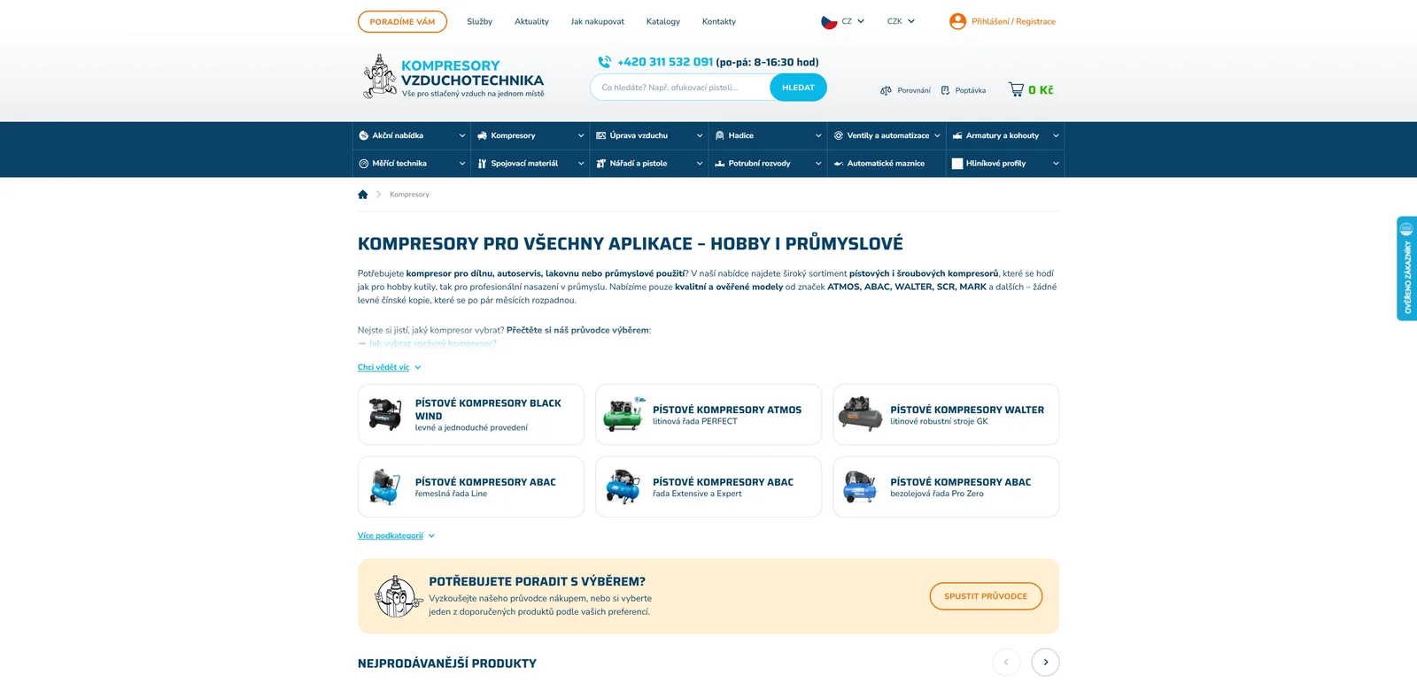
Technicians and managers dealing with the implementation of safety measures or the selection of components for a specific application can take advantage of expert consultations directly on the website. Kompresory-vzduchotechnika provides technical support in selecting compressors, piping systems and accessories for safe and efficient pneumatic operation. The range of SCR screw compressors covers industrial applications with high demands on reliability and continuity of compressed air supply.
Frequently Asked Questions
What does pneumatic safety mean in industry?
Pneumatic safety is a set of technical measures protecting workers from the risks of pneumatic systems, particularly uncontrolled pressure release, exhaust air, and mechanical movements. It includes emergency valves, lockouts, SIL safety circuits, and regular testing.
What is the difference between a pneumatic lockout and a safety switch?
A pneumatic lockout physically isolates the pressure source and prevents restart without a deliberate intervention. A safety switch only controls start/stop operation and does not provide physical protection during servicing work.
How quickly must an emergency shut-off valve react?
The emergency shut-off valve must shut off the pneumatic circuit within 15–50 ms. This reaction time is shorter than human reaction time, ensuring protection before the operator registers the hazard.
What standards govern pneumatic safety measures?
The key standards are EN ISO 13849 and EN 62061 for safety functions of control systems, ČSN EN 1088 for interlocking devices, and ISO 4414 for general requirements for pneumatic systems. Risk assessment according to EN ISO 12100 is a prerequisite for selecting the correct measures.
Why is CCF analysis important for pneumatic safety systems?
Common cause failures (CCF) can cause multiple redundant elements to fail simultaneously, for example due to pressure fluctuations or air contamination. Without CCF analysis, a seemingly redundant system may fail as a whole and fail to achieve the declared SIL level.
Recommended
- How pneumatics works: a complete guide for industry 2026
- Why use pneumatics: efficiency, speed and safety - Kompresory-Vzduchotechnika.cz
- What is pneumatic lubrication: a guide for technicians - Kompresory-Vzduchotechnika.cz
- Pneumatic tools in 2025: trends and innovations - Kompresory-Vzduchotechnika.cz