


 |
Anyone who has a small compressor in their workshop or garage does not need to deal with compressed air distribution. However, in a craft workshop or industrial operation, it is necessary to distribute compressed air to the appliances using suitable pipes and hoses. A well-designed distribution system can save a lot of money and worries.

Compressed air distribution design
| When designing the distribution system, keep the following aspects in mind: | |
|
 |
|
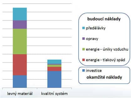
Consider which of these requirements are most important to you, and choose the piping system layout accordingly. The distribution system is usually in operation for more than 10 years. As you can see in the graph, the initial investment is often not as important as the operating costs. It does not pay off to save on the material and design of the compressed air piping distribution system. |
 |
How to proceed when designing a compressed air distribution system
Determining the pipe size and its routing is quite complex, especially if the air is routed to many different appliances. Therefore, it is often worthwhile to entrust the design of the compressed air distribution system to a designer. They will prepare a project in which you will find all the necessary information: materials, drawings, and a bill of materials used.
If you want to design the compressed air distribution system yourself, follow the procedure below.
1. Start with a layout plan of your facility
Draw a layout plan of the facility with the dimensions of the spaces and mark the locations where the following are placed:
- compressors
- points of compressed air consumption
- obstacles for routing compressed air (columns, structures, production machines, etc.)
Simple installations can be sketched on paper; for drawing more complex distribution systems, it is worth using special design software.
2. Choose the architecture – direct or ring
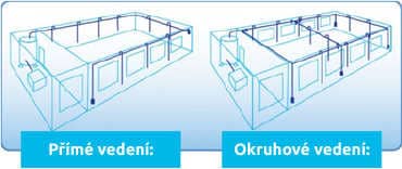
The compressed air piping distribution consists of the main, or trunk line, and connections to the consumers. The main line can be designed as:
| Direct line: A simple distribution with branches – acquisition costs are lower and it is suitable rather for small operations and craft workshops. Ring line: A closed loop – acquisition costs are usually higher, and it is suitable for larger operations. |
 |
The ring line has these advantages:
|
 |
- Once you have decided which architecture suits your installation, draw the pipe routing into the plan, including the dimensions of individual branches. Carefully mark in the plan the places the piping will have to bypass (e.g. columns). Determine the dimensions of the hall walls and the lengths of individual pipe sections.
3. Determine the maximum consumption – the consumption of the largest draw-off point
4. Choose the type of distribution
Based on the pressure, consumption and use, choose a suitable type of distribution. Pipes and hoses made of various materials are used for compressed air distribution, and the range of connecting elements, fittings and valves is very wide. The most used types of piping distributions are listed in two overviews: an overview of piping system types and an overview of piping connecting elements.
5. Choose the diameter of the distribution pipes and connecting elements
Tables and online calculators on the websites of manufacturers and e-shops with compressed air distribution will help you with the dimensions of piping and connecting elements. The following need to be entered into these tables:
- Air flow and pressure – according to the compressor used.
- Total pipe length – determine it from the plan of your distribution system.
- Equivalent pipe length – count the fittings and connectors on the longest line and look up the equivalent length for each of them in the tables; add the "equivalent pipe length" to the actual length.
- According to these parameters, you will find the recommended dimension for pipes and fittings for the total calculated length.
Hoses are used for branches from the backbone line to appliances. Determine their dimension in a similar way as for the backbone distribution.
Account for pressure drop
Air flowing through the pipe reduces the pressure, and this must be compensated by higher compressor output. Therefore, when designing a compressed air distribution system, make sure that the pressure drop is as small as possible. The length of the pipeline has the greatest influence on the pressure drop. The longer it is, the greater the drop. It can be reduced by increasing the pipe diameter, which, however, increases the acquisition cost.
The pressure drop is increased by:
- Too small pipe nominal bore
- Reduction of pipe nominal bore due to corrosion
- Rough pipe surface
- Occurrence of turbulence in fittings
The pressure drop can also be reduced by using materials with a lower coefficient of friction.
Pressure drop and pipe material
Pipes made of aluminum have the lowest pressure drop, followed by plastic pipes, while steel pipes have the largest drop. The pressure drop can also be reduced by creating a ring main distribution line.
You can roughly determine the compressed air pressure losses in a smooth hose for the pressure range of 1-15 bar using this calculator: https://e-konstrukter.cz/technicke-vypocty/162-vypocet-tlakove-ztraty-tlakoveho-vzduchu
Installation of compressed air distribution
Several principles must be observed when installing the piping:
- The piping must be accessible so that tightness can be checked or maintenance work carried out. Do not install the distribution piping in shafts or ducts, but in accessible locations.
- Install the piping with a slope of 1 to 2% in the direction of flow, so that condensed vapor and impurities flow down to the lowest point. A condensate collector with automatic drainage is installed at this point.
- Always place branches to appliances on the upper side of the pipe, so that impurities are not carried into the point of use.
- For draining condensate and impurities, install branches on the lower side of the pipe.
What material should be chosen for the compressed air distribution system?
For the main, backbone line, piping made of steel, plastic, or aluminum can be designed; occasionally, copper or brass pipes can also be used. Air is led to the consumers by means of hoses (rubber or plastic).
Backbone line material and its properties
Plastic pipes (polypropylene, polyamide) are suitable for low pressures. They are lighter, have a lower coefficient of friction, and are not threatened by corrosion.
Metal pipes (steel, galvanized steel, aluminum, brass, copper) are suitable for higher pressures.
Aluminum pipes have a very low pressure drop and a larger inner diameter for the same outer diameter.
Connections to appliances
Rubber hoses are used especially in cases where a certain flexibility of the supply piping is required. They are more expensive and more difficult to handle than plastic hoses.
Plastic hoses (made of polyamide, polyethylene, polyurethane, and teflon) are easy and quick to connect and are cheaper.
Overview of the most used types of piping systems
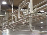
| Welded or soldered piping For long-term operation, steel pipes are joined by welding and brass pipes by soldering. The advantage of welded joints is tightness and low cost. The disadvantage is the formation of scale, which must be removed from the piping. Particles of rust may also fall off the welds and contaminate the compressed air. Therefore, an air treatment unit with a filter must be used. |
 |
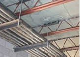
| Screwed piping Galvanized steel pipes are connected with fittings. With these joints, attention must be paid to leaks and to rust-through in places where the protective layer is damaged, e.g. at threads. Therefore, even when using screwed pipes, it is necessary to use air treatment units. |
 |
|
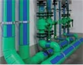
Plastic piping |
 |
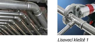
| Press-fit piping systems Press-fit systems are among the most widely used today because they have many advantages:
|
 |
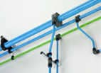
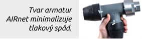
| Aluminum screwed piping Aluminum pipes can be connected, e.g., with plastic couplings of the AIRnet system with nominal bores from 20 to 100 mm (3/4" to 4"). AIRnet piping system |
 |
AIRnet joints are resistant to:
|
 |
| Aluminum pipes are supplied with a double bend for creating an offset from the main line to the wall. AluNET aluminum pipes for a maximum pressure of 16 bar and a maximum temperature of +100°C with an SZÚ certificate according to the European directives PED (Pressure Equipment Directive) and CPR (Construction Product Regulation). AluNET pipes can be connected with Tectite Air, Schneider (15-28mm), John Guest and Festo piping systems. | 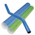 |
Piping distribution systems from aluminum profiles
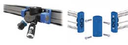
Sico Alu – aluminum piping for workshops and laboratories
|
 |
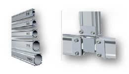
Prevost AMPS system for production facilities
|
 |
Overview of piping connection elements
