
FUTURA two-piece air treatment units for ATEX environments up to 16 bar
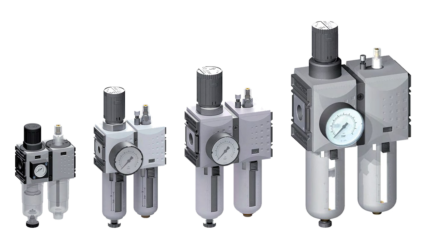
The FUTURA two-piece unit combines a pressure regulator with a 5 µm filter and a lubricator. It cleans the air, reduces it to the set pressure and adds oil mist to it for tools, cylinders and valves.
It comes in four sizes with G 1/4" to 1" threads and in ranges from 0.1–1 bar to 0.5–16 bar. The pressure gauge is included. Compared with the three-piece unit, it is one module narrower.
Which version to choose
Two-piece unit
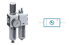
Sizes 1, 2 and 4, G 1/4" to 1" threads, 50 mm pressure gauge. The 0.5–8 bar range is the most versatile.
Size 0
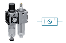
The smallest unit, G 1/4", with a micro-lubricator and a compact pressure gauge. Inlet pressure up to 12 bar.
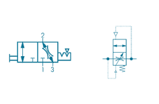
Safety version
With an upstream ball valve that you lock with a padlock, and with a soft-start valve for gradual pressure build-up.
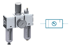
Three-piece unit
Filter, regulator and lubricator as three separate modules. Same flow, one module wider.
Two-piece units by size
Rows are setting ranges, columns are threads. The pressure gauge matches the range.
The dimensions are the width × height of the whole unit. Inlet pressure 1.5–16 bar, for size 0 1.5–12 bar. The 0.5–8 bar range is the most versatile. Size 0 is not for use in potentially explosive atmospheres.
#showmore#
How the unit works
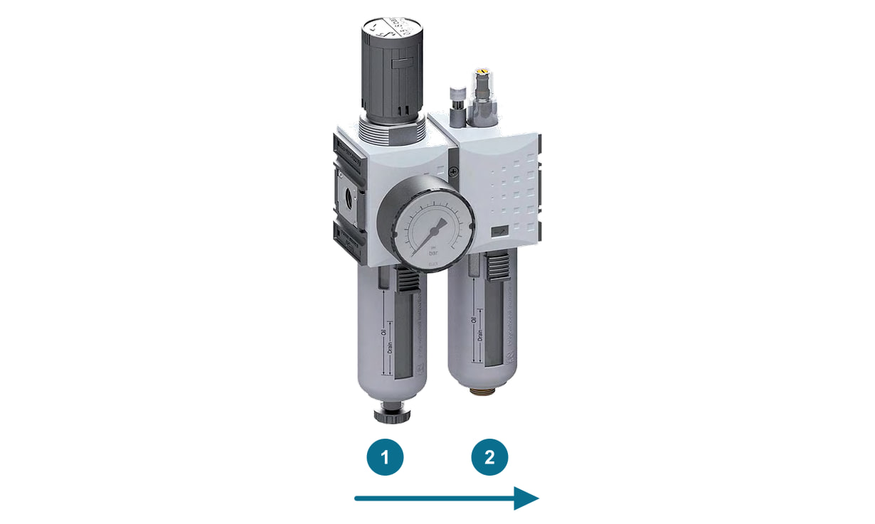
The air enters the filter regulator. Centrifugal force separates water droplets, the 5 µm element traps dirt and the regulator reduces the pressure to the set value. It relieves excess outlet pressure by itself. In the lubricator, oil mist is added to the air.
The lubricator only adds oil above a certain flow, for size 1 from 90 l/min at 6 bar. You set the dose with the screw on the sight dome, as a guide 1 to 2 drops per minute at 1,000 l/min. Size 0 has a micro-lubricator with a dose of about 10 to 20 drops.
The unit delivers lubricated air. Take oil-free air, for example for spray guns, before the lubricator, for instance with a FUTURA manifold module.
Flow, condensate and oil
| Data for two-piece units by size | |||||
|---|---|---|---|---|---|
| Size | Flow (l/min) | Min. flow for oiling (l/min at 6 bar) | Max. condensate in filter (cm³) | Oil capacity (cm³) | Width × height (mm) |
| 0 | 800 | 26 | 16 | 35 | 86 × 168 |
| 1 | 1,750 | 90 | 28 | 40 | 104 × 225 |
| 2 | 3,500 | 70 | 49 | 80 | 126 × 257 |
| 4 | 12,000 | 115 | 87 | 181 | 170 × 329 |
Bowl and condensate drain
The standard version has plastic bowls and a semi-automatic filter condensate drain. You choose another version as a variant on the product page. In size 0, you can also choose a 40 mm pressure gauge instead of the compact one as a variant.
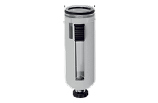
Plastic bowl
Transparent polycarbonate bowl, in sizes 1 to 4 in a protective guard. You can see the whole condensate and oil level.
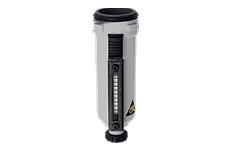
Metal bowl
For more demanding environments. With a sight glass in sizes 1 to 4, without one in size 0.
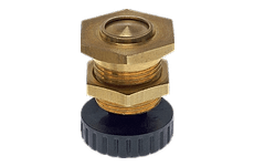
Semi-automatic drain
Condensate from the filter drains by itself when the pressure in the bowl drops, for example after the supply is shut off. In continuous operation, keep an eye on the level.
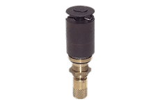
Automatic drain
A float releases the condensate during operation as soon as it rises. The version closed when depressurised stays closed after the air is switched off.
| Bowl and drain versions by size | ||||
|---|---|---|---|---|
| Bowl and drain | Size 0 | Size 1 | Size 2 | Size 4 |
| Plastic, semi-automatic (standard) | yes | yes | yes | yes |
| Plastic, automatic | yes | yes | yes | yes |
| Plastic, automatic closed when depressurised | yes | yes, except G 1/4" 0.2–4 bar | G 1/2" only, except 0.2–4 bar | G 1" only |
| Metal, semi-automatic | yes | yes | yes | yes, except G 3/4" 0.2–4 bar |
| Metal, automatic | yes | yes | – | – |
You can lead the condensate away through a hose. With the automatic drain, the hose screws into the G 1/8" thread in the drain outlet.
Safety version
A ball valve and a soft-start valve are fitted before the unit. Before maintenance you close the valve, the outlet is exhausted and you lock the valve with a padlock. At start-up, the soft-start valve fills the air line gradually, so the cylinders do not move abruptly. You set the filling time with a screw.
| Safety two-piece units | |||
|---|---|---|---|
| Size | Thread | Range (bar) | Order number |
| 1 | G 1/4" | 0.5–8 | CL14-8F-SI |
| 1 | G 3/8" | 0.5–8 | CL38-8F-SI |
| 2 | G 3/8" | 0.5–8 | CL382-8F-SI |
| 2 | G 1/2" | 0.5–8 | CL12-8F-SI |
| 2 | G 1/2" | 0.5–10 | CL12-10F-SI |
| 4 | G 3/4" | 0.5–8 | CL34-8F-SI |
| 4 | G 1" | 0.5–8 | CL10-8F-SI |
The safety version is only for sizes 1, 2 and 4. You can select it with an automatic drain on the product page, except for CL12-10F-SI.
Oil and filling
Top up the oil when the level drops to the lower mark. Manually: remove the lubricator bowl, pour in oil up to the mark and refit the bowl until the catch clicks into place. Sizes 1 to 4 can also be filled during operation through a hose with a G 1/8" thread and the filling button; the unit must be under pressure.
The catalogue recommends ISO VG 32 class oil (CL32 to DIN 51517). We offer SOL for temperatures above +5 °C, SOLWI for operation with larger amounts of condensate and the food-grade SOLLE. Oil mist is harmful to health; use a unit with a lubricator only in closed pneumatic systems.
Potentially explosive atmospheres
Two-piece units in sizes 1, 2 and 4 are mechanical devices with no ignition source of their own. According to the declaration regarding Directive 2014/34/EU, you can use them in zones 1 and 2 (gases IIA, IIB, IIC) and 21 and 22 (dust IIIA, IIIB), temperature class T4, under the conditions described for the entire FUTURA range. Size 0 is not for use in potentially explosive atmospheres.
Mounting
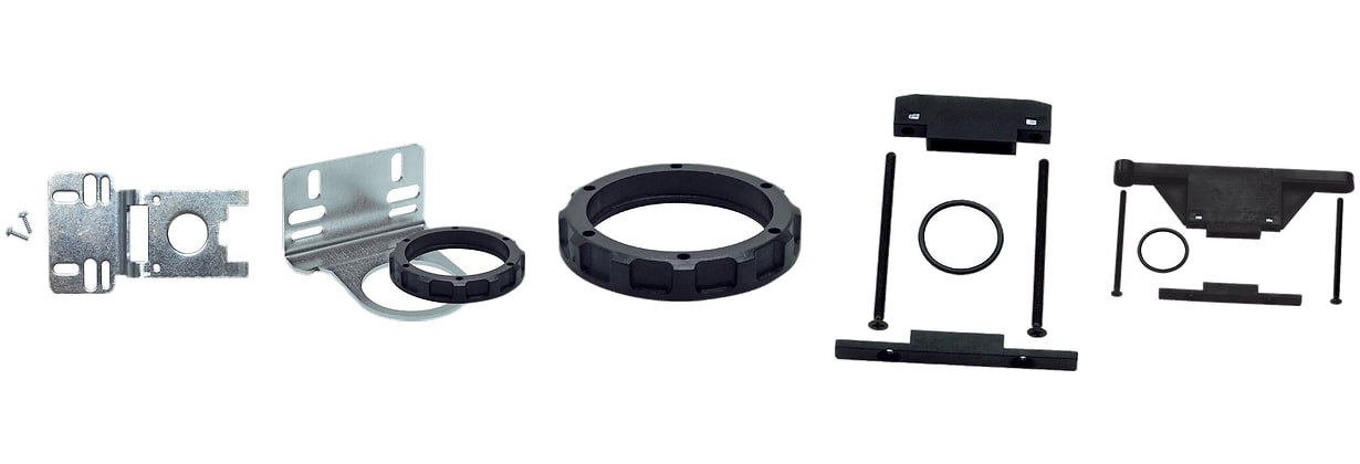
Mount the unit upright only, bowls down, and in the direction of the arrow on the body. You fix it to a wall with a mounting bracket or a connection kit with wall bracket. Threaded wall brackets screw onto the start and end of the unit, so you can replace the unit without removing the piping.
You can build the regulator part into a panel with a nut. Neither the mounting bracket nor the connection kits are included; you choose them by size.
Spare parts and accessories by size
On the page of each unit, the parts for its size are offered as related products.
| Spare parts and accessories for units | ||||
|---|---|---|---|---|
| Part | Size 0 | Size 1 | Size 2 | Size 4 |
| Filter element 5 µm | FV-1F | FV-2F | FV-4F | |
| Plastic bowl, semi-automatic drain | BDF00 | BF1F | BF2F | BF4F |
| Plastic bowl, automatic drain | BF1-AM | BF1F-AM | BF2F-AM | BF4F-AM |
| Plastic bowl, automatic drain closed when depressurised | BF1-AMNC | BF1F-AMNC | BF2F-AMNC | BF4F-AMNC |
| Metal bowl, semi-automatic drain | BDF00-M | BFM1F | BFM2F | BFM4F |
| Metal bowl, automatic drain | BDF00-MAM | BFM1F-AM | BFM2F-AM | BFM4F-AM |
| Metal bowl, automatic drain closed when depressurised | BDF00-MAMNC | BFM1F-AMNC | BFM2F-AMNC | BFM4F-AMNC |
| Bowl sealing ring | OR1 | OR1F | OR2F | OR4F |
| Plastic lubricator bowl | BDO00 | BOL1F | BOL2F | BOL4F |
| Metal lubricator bowl | BDO00-M | BOLM1F | BOLM2F | BOLM4F |
| Lubricator sight dome | TROPFOLF | |||
| Spare regulator diaphragm | MEMBRANER014F | MEMBRANER14F | MEMBRANER12F | MEMBRANER34F |
| Spring cover | FEDERHAUBE0F | FEDERHAUBE1F | FEDERHAUBE2F | FEDERHAUBE4F |
| Spare knob | FEDERHAUBE0F-RAD | FEDERHAUBE1F-RAD | FEDERHAUBE2F-RAD | |
| Padlock for the knob | – | VHS20 | ||
| Panel mounting nut | SM1 | SM1F | SM2F | SM4F |
| Mounting bracket with screws | W0F | W1F | W2F | W4F |
| Connection kit | KP0F | KP1F | KP2F | KP4F |
| Connection kit with wall bracket | KPW0F | KPW1F | KPW2F | KPW4F |
Maintenance
The filter element gradually clogs and needs replacing. Depressurise the unit before replacing it. Pull the filter bowl catch down, turn the bowl to the left and remove it. Unscrew the element end piece and replace the element. Fit the bowl rotated by 45° and turn it to the right until the catch audibly clicks into place.
Before putting the unit into operation, check the oil level and the dose setting. Clean plastic bowls only with a damp cloth and water or a mild detergent; solvents damage polycarbonate.
Ventilek’s tip
Two-piece or three-piece? They have the same flow. The two-piece unit is narrower, has fewer joints and is the only one made as a safety version. Choose the three-piece unit when you want the filter as a separate module.
- What is the difference between a two-piece and a three-piece unit?
- The two-piece unit has the filter and regulator in one body; the three-piece unit has them as separate modules. Flow, filtration, bowls and ranges are the same; the two-piece unit is one module narrower.
- Is the pressure gauge included?
- Yes. Size 0 has a compact pressure gauge, with a 40 mm pressure gauge as a variant. Sizes 1 to 4 have a 50 mm pressure gauge.
- Are the mounting bracket and connection kit included?
- No, you choose them separately according to the unit size. You will find them in the parts table.
- Which oil should I use?
- The catalogue recommends ISO VG 32 class oil (CL32 to DIN 51517). For food processing, we offer a food-grade oil.
- When should I choose the automatic drain?
- When the equipment runs for long periods without a break. The semi-automatic drain only releases condensate when the pressure in the bowl drops, so in continuous operation the condensate could overflow into the air line.
- Is it suitable for potentially explosive atmospheres?
- Sizes 1, 2 and 4 are, in zones 1, 2, 21 and 22 according to the declaration regarding Directive 2014/34/EU. Size 0 is not.
Inlet pressure 1.5–16 bar (size 0: 1.5–12 bar), setting ranges 0.1–16 bar, 5 µm filtration, working temperature −10 to +50 °C, compressed air and neutral gases. Relief of excess outlet pressure, pressure gauge included, outlet air with oil mist.


