How to proceed when designing your own compressed air distribution system?
Correct material selection
To supply the compressed air produced by the compressor to the points of consumption, piping systems are generally used. In our catalog, you will find several piping systems, of which we prefer three systems with modern connections using push-in fittings or tightening nuts:
| Piping system |  |
 |
 |
| Field of application | small craft workshops | larger craft and maintenance workshops smaller manufacturing plants |
medium and large manufacturing plants |
| External dimension | Ø15 to 28 mm | Ø20 to 63 mm | Ø20 to 158 mm |
| Fittings | push-in | with tightening nut | with tightening nut clamps with screws |
| Pipes | grilamid PA12 aluminum |
aluminum | aluminum |
All systems are characterized by high simplicity of assembly, a low pressure drop allowing for significant savings in air production, and high resistance to condensate, contributing to long-term trouble-free use.
Piping distribution architecture
Before selecting the necessary pipes and fittings, always draw a situational plan of your facility. Mark the locations where the compressor will be placed and where the individual workstations are. Next, draw where you intend to route the piping, both the main backbone line and the individual drops to the consumption points. When designing, take into account any obstacles the piping must bypass (e.g., pillars). Determine the dimensions of the hall walls and the lengths of the individual pipe sections.
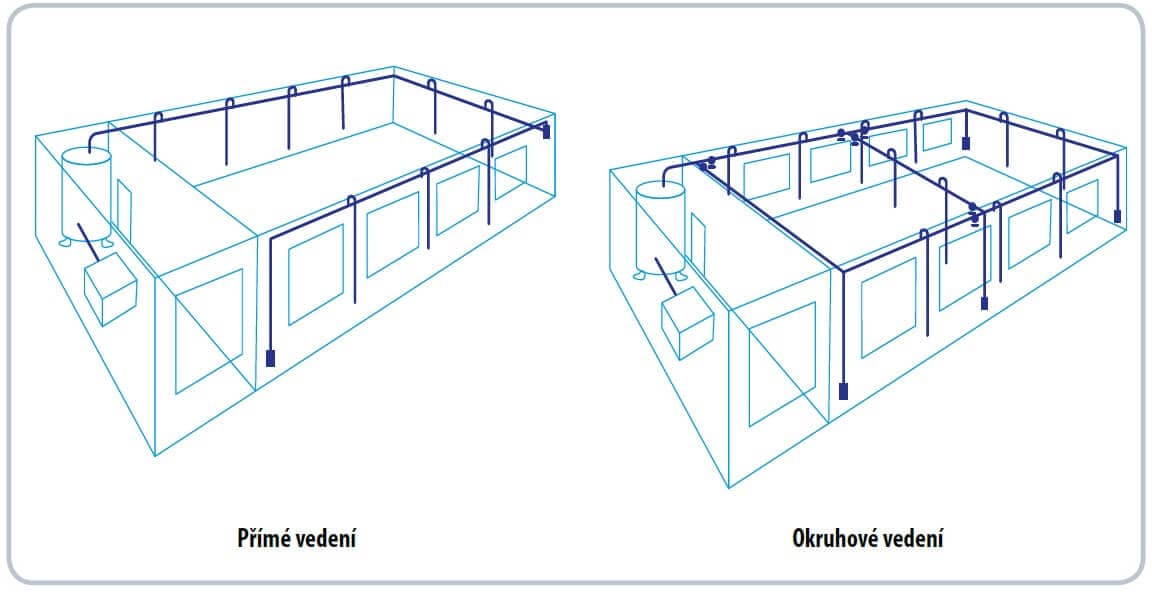
During the design, you can also choose the shape of the piping – whether it will be a direct or a ring line. Although a ring line is more expensive, it provides the user with advantages in terms of using smaller pipe dimensions, even air distribution to all consumers regardless of distance from the compressor, and the ability to shut down only certain sections of the distribution in case of maintenance. Finally, determine the required flow rates for all consumption points and calculate the necessary fittings.
Pipe dimensioning in 10 steps
Determining the size of the piping is a relatively complex process. The easiest way to make your job easier is to hand the entire project over to an architect or designer, who will create a project for the customer containing all necessary information: materials, drawings, and a bill of materials. If you want to design the piping yourself, you can use the following procedure:
- choose the shape of the piping, whether direct or ring
- determine the length of the main backbone line from the compressor to the furthest point
- determine the flow through the piping according to the compressor's performance
- determine the maximum air consumption of one consumption point to dimension the size of the drop from the backbone line
- determine the number of individual fittings and valves along the backbone branch from the compressor to the furthest point in the distribution
- choose the piping system: Air Push, SicoAir, or AIRnet
- select the appropriate table for the piping system and line type and enter the flow of the backbone branches and the maximum length of the backbone branch; read the required pipe dimension from the table
- for the given pipe size, determine from the table the so-called equivalent pipe length according to the type and number of individual fittings and valves used on the backbone line in the longest route
- add the equivalent length to the original length of the piping line and check, according to the instructions in step 7, whether the dimension is correct; if the dimension increased due to the equivalent length, use a larger dimension for both pipes and fittings
- determine the dimension of the drops from the backbone line to the appliances in a similar manner
Tables for piping distribution design
All flow values in the following tables are given for a pressure of 7 bar; for a design at a different pressure, please contact us.
|
||||
| Equivalent lengths of fittings | Size (mm) | |||
| 15 | 18 | 22 | 28 | |
| Elbow | 0.7 | 1.0 | 1.3 | 1.5 |
| T-piece | 0.8 | 1.0 | 1.5 | 2.0 |
| Reducer 2d –> d | 0.4 | 0.5 | 0.5 | 0.6 |
| Ball valve | 0.1 | 0.2 | 0.3 | 0.4 |
(The tables for Sico Air and AIRnet and the calculation tables for flows are preserved in the full code with the same structure as Air Push above...)
Example of a piping distribution design
We need to design a piping distribution in a hall with a length of 150 m and a width of 100 m. The distribution pressure will be 7 bar, and the compressor delivers 3,000 l/min. The distribution drops have a height of 10 m, and a flow rate of 500 l/min is required in each. We will use a ring line, and we propose the AIRnet system as the piping material, see the image.
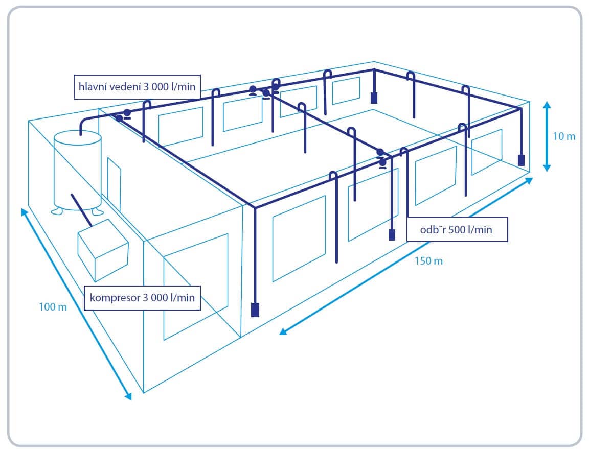
The furthest point from the compressor room is completely to the right in the image. **The length of the line to it is**: hall length 150 m + hall width 100 m = 250 m. To dimension the backbone distribution, we use the corresponding table for a ring line from the AIRnet system. For a length of 250 m and a flow rate of 3,000 l/min, we read a value of 40 mm.
Now we determine the number and type of fittings on the route to the furthest point and calculate the equivalent length in the assumed dimension of 40 mm according to the AIRnet system table:
Elbow 2 pcs × 2 m = 4 m
T-piece 8 pcs × 2.5 m = 20 m
Ball valve 3 pcs × 0.5 m = 1.5 m
The total equivalent length is thus 25.5 m + the original length of 250 m = 275.5 m.
We look at the distribution dimensioning table again, and even for a length of 300 m, the dimension at a flow rate of 3,000 l/min remains the same, i.e., we select the backbone line in pipes with an outer diameter of 40 mm. Next, we determine the dimension of the drops; from the table for dimensioning a direct line in the AIRnet system, we read that for a length of 10 m and an expected flow to the consumption point of 500 l/min, a dimension of 20 mm can be chosen.
When is it worth considering compressed air distribution?
- If you need to supply compressed air to multiple appliances
- When you frequently work with compressed air in several places in the workshop
- If automated lines in industrial operations depend on compressed air
When compressed air distribution makes no sense
- In the case of a single application
- If you own a mobile compressor for minor jobs
- In a small workshop or garage where hoses are sufficient
Important information for you – A well-designed air distribution can save a lot of money and hassle!
Compressed air distribution systems:
- TECTITE - a simple system of push-in pipes and fittings for workshops and industrial operations
- AIRnet - a top-class connection system made of lightweight aluminum pipes
- SICOAIR - an extremely efficient modular system with minimal pressure drop
- SICOalu2 - an aesthetically perfect system for workshops and laboratories
- SICO110 - a system with large aluminum profiles for extensive installations